Drones with Thermal Cameras: OEM Integration, 640 LWIR Payloads & Selection Guide
Drones with Thermal Cameras: OEM Integration, 640 LWIR Payloads & Selection Guide
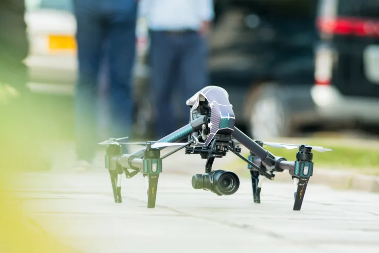
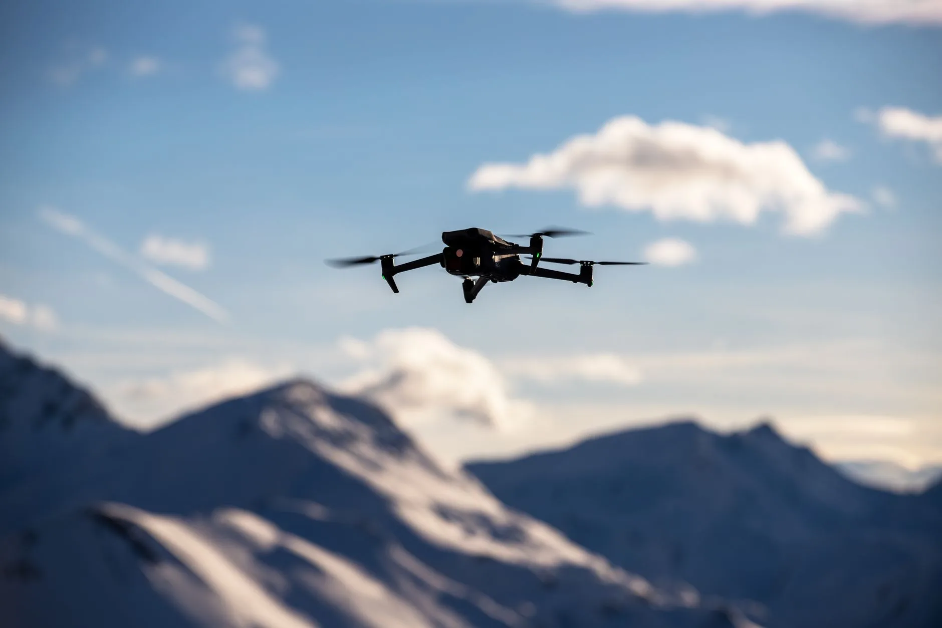
Thermal imaging used to be the exclusive sandbox of tier-one defense contractors with bottomless budgets. Not anymore. Over the last few years, Long-Wave Infrared (LWIR) has shifted into a standard payload requirement across commercial UAVs, tactical micro-drones, border interdiction airframes, and robotic inspection crawlers. When an autonomous bird flies into zero-lux nights, thick coastal fog, industrial chemical plumes, or harsh tree canopy shadows, standard electro-optical (EO) visible cameras hit a hard wall. They lose contrast, drop target lock, and leave your operators blind. Equipping modern drones with thermal cameras bridges that gap by pulling data directly from physical heat emissions rather than bouncing ambient light off a target.
Here’s the deal when you’re actually building these payloads in the shop: balancing Size, Weight, Power, and Cost (SWaP-C) against raw optical reach is a brutal balancing act. Integrators have to hit tight Instantaneous Field of View (IFOV) numbers, maintain sub-pixel thermal sensitivity, and keep the airframe light enough to actually stay in the air. On top of that, the old-school approach of beaming raw thermal video down to a laptop at the Ground Control Station (GCS) for processing is dead on arrival. It creates unacceptable latency, falls apart under RF jamming or signal drops, and buries the pilot under cognitive overload.
Look at how modern tactical platforms operate: the compute lives right on the aircraft. Dedicated edge Neural Processing Units (NPUs) run quantized neural nets directly on the payload board, fusing visible and thermal streams, locking onto multi-class targets, and driving gimbal motors in real time without caring whether the ground link is alive or dead.
This technical integration guide provides drone design engineers, systems integrators, and technical payload specialists with an end-to-end blueprint for selecting, interfacing, and deploying modular dual-spectrum visible/thermal payloads, 640×512 uncooled microbolometers, and embedded AI tracking engines on open-source and industrial flight platforms.
Table of Contents
- 👉 1. Detector Physics: Uncooled VOx LWIR Microbolometers in UAV Payloads
- 👉 2. Dual-Spectrum Optical Architecture & Sensor Fusion
- 👉 3. Onboard Edge-AI Acceleration & Low-Latency Tracking Pipelines
- 👉 4. Flight Controller Integration, SWaP-C & Protocol Architectures
- 👉 5. OEM Dual-Spectrum Module Specifications & Direct Comparison
- 👉 6. Engineering Selection Framework: Radiometric Payloads vs. Edge Tracking Modules
- 👉 7. Frequently Asked Questions (Deep-Dive Technical FAQ)
1. Detector Physics: Uncooled VOx LWIR Microbolometers in UAV Payloads
Infrared radiation breaks down into very specific atmospheric transmission windows. Short-Wave Infrared (SWIR, 1.4 to 3 µm) needs active laser illumination or starlight reflection to be useful, while Mid-Wave Infrared (MWIR, 3 to 5 µm) requires heavy, power-hungry, cryogenically cooled Stirling assemblies that destroy battery life on anything smaller than a Group 3 UAS. For tactical micro-drones and commercial multicopters, the long-wave infrared band (LWIR, 8 µm to 14 µm) is the undisputed sweet spot. Terrestrial objects running between -40°C and +80°C hit their peak blackbody radiation curves right in this band under Planck’s Law, giving your system completely passive detection in total darkness.
Microbolometer Operating Principles
At the center of an aerial thermal core sits an uncooled microbolometer focal plane array (FPA). Think of it as a microscopic 2D grid of tiny thermal absorption membranes suspended over a silicon Readout Integrated Circuit (ROIC) by ultra-fine structural bridges. When incoming LWIR photons strike those membranes, their physical temperature climbs. That temperature bump alters the material’s electrical resistance. The ROIC sweeps the array, picks up those tiny resistance shifts, and converts them into raw digital voltage counts via high-resolution analog-to-digital converters (ADCs).
Vanadium Oxide (VOx) vs. Amorphous Silicon (α-Si)
The thin-film chemistry you choose for that resistive element decides whether your sensor delivers crisp tracking or a noisy, washed-out smear. In the drone world, it boils down to Vanadium Oxide (VOx) versus Amorphous Silicon (α-Si):
| Detector Parameter | Vanadium Oxide (VOx) | Amorphous Silicon (α-Si) |
|---|---|---|
| Typical NETD (Thermal Sensitivity) | ≤ 35 mK to 50 mK at f/1.0 | 50 mK to 80 mK at f/1.0 |
| Temperature Coefficient of Resistance (TCR) | High (~2% to 3% per Kelvin) | Moderate (~1.5% to 2.5% per Kelvin) |
| 1/f Electronic Noise | Significantly lower 1/f noise floor | Higher 1/f noise floor |
| Thermal Time Constant (τ) | Fast (8 ms to 12 ms) | Slower (12 ms to 18 ms) |
| Thermal Smearing at High Dynamic Speeds | Minimal (sharp edges on fast targets) | Moderate motion blur / ghosting |
In real-world flight testing, when an aircraft is pulling sharp banking maneuvers or tracking high-speed targets across choppy terrain, VOx microbolometers outperform α-Si across the board. The higher Temperature Coefficient of Resistance and suppressed 1/f noise floor yield a vastly superior Noise Equivalent Temperature Difference (NETD). Hitting ≤40 mK means subtle thermal differentials—like fresh tire friction tracks on concrete, camouflaged personnel tucked behind scrub brush, or minor insulation gaps—stand out cleanly instead of disappearing into digital snow.
Pixel Pitch Scaling and Optomechanical Weight Reduction
Modern lithography has successfully pushed pixel pitch down from legacy 25 µm and 17 µm standards to 12 µm architectures. Why does that matter to an airframe designer? Shrinking the pixel pitch shrinks the physical footprint of the FPA die for any given resolution. A 640×512 array on a 17 µm pitch has a diagonal measurement around 13.6 mm. Move that same resolution to a 12 µm pitch, and the diagonal drops to just 9.6 mm.
That reduction creates a massive mechanical cascade across your gimbal design. To achieve the exact same Instantaneous Field of View (IFOV) and spatial ground resolution, a 12 µm sensor uses an optical objective with a significantly shorter focal length and a smaller clear aperture diameter. LWIR glass is made from dense materials like monocrystalline Germanium (which carries a hefty density of 5.323 g/cm³) or chalcogenide glass. Trimming lens diameter cuts optical front-element mass by 40% to 55%, instantly reducing motor torque demands on the gimbal and keeping overall airframe weight down.
When an airframe demands maximum area coverage per pass without sacrificing ground sampling distance, jumping from standard 640 cores to megapixel arrays like the HR-1280 1280×1024 Uncooled LWIR Thermal Imaging Module delivers four times the pixel count for long-range surveillance.
2. Dual-Spectrum Optical Architecture & Sensor Fusion
Relying solely on an uncooled LWIR thermal channel has clear tactical limitations. Standalone thermal video doesn’t provide color, struggles with painted placards or registration numbers, and gets washed out during “thermal crossover”—those dawn and dusk transition windows when background terrain and target temperatures equalize. Visible electro-optical (EO) cameras deliver crisp edge contrast and natural color, but become completely blind in low-light, shadowed, or obscurant-filled conditions.
Dual-spectrum payloads solve this by packaging an EO visible sensor alongside an uncooled LWIR microbolometer on a rigid, shared optomechanical bench, aligning their optical axes to feed complementary data into a unified pipeline.
Optomechanical Alignment and Parallax Compensation
Mounting two optical barrels side by side inevitably introduces baseline physical separation between the visible entrance pupil and the thermal objective lens. If you are looking at targets inside 30 meters, this baseline causes geometric parallax, throwing target coordinates out of alignment between channels. Modern edge processing engines correct this mathematically on the fly:
- ⚙️ Affine and Homography Calibration: The payload bench undergoes multi-distance optical collimation at the factory, mapping precise rotation, scaling, and translation matrices across all focal points.
- ⚙️ Dynamic Real-Time Warping: The onboard vision engine continuously reads laser rangefinder (LRF) telemetry or depth maps, applying affine transformations to warp the wider EO feed so it aligns perfectly with the thermal sensor’s perspective.
| Optical Channel Feature | TC01-DUAL Dual-Spectrum Module | TM02-SOLO T Dual-Spectrum Module |
|---|---|---|
| Visible (EO) Resolution & Rate | 2160 × 1440 at 60 Hz | 1920 × 1080 at 120 Hz |
| Visible Optical Format & Focal Length | 1/1.8-inch sensor, 4.37 mm lens | 1/1.8-inch sensor, 8.45 mm lens |
| Visible Field of View (D / H / V) | 131.6° / 109.0° / 57.5° (Wide-Angle) | 66.3° / 57.1° / 30.4° (Telephoto Match) |
| Visible Low-Light Sensitivity | 0.001 lux low-light star-level sensor | 0.001 lux low-light star-level sensor |
| Thermal Core Resolution & Rate | 640 × 512 at 50 Hz | 640 × 512 at 50 Hz |
| Thermal Pixel Pitch & Spectral Band | 12 µm, 8–14 µm LWIR | 12 µm, 8–14 µm LWIR |
| Thermal Focal Length & FOV | 9.1 mm (D 61.8° / H 47.7° / V 38.2°) | 9.1 mm (D 61.8° / H 47.7° / V 38.2°) |
Dual-Light Image Fusion and PIP Presentation
Once the geometric registration is locked in, the onboard processor executes dual-stream presentation modes:
- ✅ Picture-in-Picture (PIP): Keeps the broad operational context alive across the wide EO feed while showing an active, high-contrast thermal sub-window over designated heat signatures.
- ✅ Dual-Light Edge Fusion: The vision processor extracts high-frequency spatial contours from the visible sensor using Sobel or Laplacian operators, overlaying sharp edge data right on top of the thermal palette (White-Hot, Black-Hot, or Ironbow). This combines raw heat detection with readable signage, structural outlines, and fine foliage details.
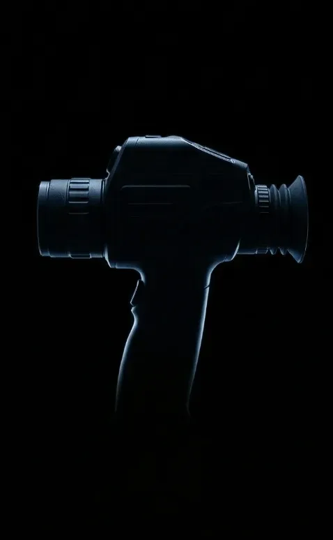
For joint air-to-ground operations, cross-referencing aerial dual-spectrum feeds with dismounted spotters using tactical handheld units like the Handheld Infrared Thermal Observation Instrument maintains clear target custody across teams.
3. Onboard Edge-AI Acceleration & Low-Latency Tracking Pipelines
Relying on a ground station laptop to run target detection over a wireless video link creates massive failure points in real operations:
- ⚠️ High Downlink Latency: Encoding, transmitting, and decoding video across an RF link introduces 80 ms to 300 ms of transport lag. By the time a bounding box gets drawn on the ground, the gimbal tracking loop has already fallen behind high-speed targets.
- ⚠️ RF Signal Dropouts & EW Jamming: In dense urban corridors, deep valleys, or contested RF environments, dropped packets cause ground-based trackers to instantly lose state estimation and drop target lock.
- ⚠️ Compression Artifact Degradation: Heavy H.264/H.265 compression smooths out subtle thermal edge gradients, degrading the feature maps needed by convolutional neural networks for accurate multi-class classification.
Embedded NPU Acceleration Architecture
Modern dual-spectrum tracking modules move the compute directly onto the payload board. For example, the Camcuda TC01-DUAL packs an integrated 4 TOPS edge inference engine, while the Camcuda TM02-SOLO T steps up to a 6 TOPS NPU backed by an Arm Cortex-A76 (2.4 GHz) and Cortex-A55 (1.8 GHz) heterogeneous CPU cluster.
These onboard chips read raw camera frames straight over low-overhead MIPI CSI-2 or direct high-speed internal buses. The raw video feeds directly into quantized INT8 neural nets—like custom YOLO models tuned for aerial angles. The pipeline executes deterministically onboard:
- ⚙️ Hardware Frame Synchronization: Simultaneously buffers 120 Hz EO and 50 Hz thermal frames, matching hardware timestamps to eliminate temporal skew.
- ⚙️ Deep Neural Inference: Runs multi-class classification (personnel, light vehicles, heavy trucks, maritime assets) down to a tiny 10×10 pixel detection threshold.
- ⚙️ Spatial Multi-Object Tracking (MOT): Implements Kalman filtering paired with Hungarian data association to assign persistent target IDs across up to 120 simultaneous tracks.
- ⚙️ Direct Gimbal Slew: Computes angular azimuth and elevation error vectors relative to boresight, driving closed-loop gimbal stabilization in just 8 ms to 30 ms without touching the ground link.
Autonomous Tracking Modes & Kinematic Trajectory Handling
These dual-spectrum tracking engines provide flexible lock modes built to survive aggressive maneuvers and line-of-sight breaks:
- ✅ Reticle Locking & Close-to-Lock: Operators can manually drop a crosshair over a target or set up automatic bounding-box locks the moment a target enters a monitored sector.
- ✅ Lost-Target Recall & Route Pre-Mapping: When a tracked vehicle ducks into a tunnel, passes behind dense tree cover, or gets occluded by a building, the tracking engine projects a kinematic velocity vector. It pre-maps the exit trajectory and snaps the lock back into place the moment the thermal signature reappears.
- ✅ High-Speed Intercepts: The tracking engine easily manages severe relative motion, holding lock on targets moving at 140 km/h on the TC01-DUAL and up to an extreme 450 km/h on the TM02-SOLO T for high-speed intercept and fixed-wing reconnaissance.
High-speed vision processing demands dependable transmission pipelines similar to standards established in industrial automation frameworks, such as the JIIA CoaXPress Certification Program, ensuring frame drops and pipeline stalls don’t occur during high-G flight.
4. Flight Controller Integration, SWaP-C & Protocol Architectures
Integrating dual-spectrum thermal payloads into an airframe demands careful attention to electrical power conditioning, mechanical weight distribution, thermal dissipation paths, and autopilot communication protocols.
Electrical Power Conditioning & Ground Loops
Dual-spectrum AI modules operate across a recommended DC input range of 9 V to 16 V DC. On modern multirotors powered by 4S to 6S (or higher) LiPo packs, you should never power the payload directly from the main battery bus. Motor throttle spikes, regenerative ESC braking, and switching noise dump significant voltage ripple and inductive spikes into the lines, which can degrade sensitive microbolometer ROIC circuitry or brown out onboard NPUs.
Integrators must implement dedicated, low-noise DC-DC buck converters with LC filtering and Transient Voltage Suppression (TVS) diodes. Furthermore, microbolometer Non-Uniformity Correction (NUC) shutter cycles draw sudden current pulses; isolating the flight motor ground from the video payload ground prevents ground loops that cause horizontal noise lines across the thermal display.
Mechanical SWaP-C & Thermal Dissipation Management
Payload weight directly dictates flight endurance: every extra 50 grams cuts into loiter time. The Camcuda TC01-DUAL maintains an ultra-compact processing board footprint of just 38 × 38 × 24.5 mm with a standard 25.5 × 25.5 mm mounting pattern, while the high-compute TM02-SOLO T measures 45 × 45 × 26 mm with a 42.5 × 42.5 mm mounting pattern.
Because onboard 4 TOPS and 6 TOPS NPUs generate steady heat during continuous inference, enclosure engineering requires proper conductive heat sinking. Heat must be pulled away from the compute board using thermal gap pads mated directly to the airframe chassis or aluminum gimbal enclosure—and critically, directed away from the thermal microbolometer core. Dumping compute heat into the LWIR sensor body creates thermal gradients across the FPA, triggering frequent NUC shutter freezes and degrading thermal image clarity.
Autopilot Protocols: CRSF and MAVLink Architecture
To support autonomous flight operations, modern tracking modules interface natively with common flight control stacks like ArduPilot and BetaFlight:
- ⚙️ CRSF (Crossfire Serial Protocol): A high-baud, low-latency bi-directional UART protocol. The tracking module reads RC channel commands (switching between visible, thermal, PIP, and fusion modes; activating tracking lock) and streams high-rate angular offset data directly to the flight controller at over 50 Hz.
- ⚙️ MAVLink Telemetry: For waypoint-driven autonomous missions, the module sends standard MAVLink messages (such as
CAMERA_TRACKING_IMAGE_STATUSandGLOBAL_POSITION_INT) over serial telemetry. This allows ArduPilot to enter “Guided Loiter” mode, automatically circling the aircraft around the target’s estimated GPS coordinates based on the thermal visual lock.
For a detailed breakdown of core selection, optical paths, and mechanical integration trade-offs, consult the Infrared Camera Module OEM Buying Guide. For mission-critical payloads operating in extreme environments, payload engineers cross-reference structural vibration hardening against defense aerospace standards established by industry leaders such as BAE Systems.
5. OEM Dual-Spectrum Module Specifications & Direct Comparison
The following engineering matrix provides a direct, comprehensive technical comparison between Camcuda’s premier dual-spectrum edge-AI tracking modules designed for UAV integration:
| Specification Dimension | TC01-DUAL Dual-Spectrum Module | TM02-SOLO T Dual-Spectrum Module |
|---|---|---|
| Edge AI Compute Capability | 4 TOPS Dedicated NPU | 6 TOPS Dedicated NPU |
| CPU System Architecture | Embedded High-Efficiency Vision Core | Arm Cortex-A76 (2.4 GHz) + Cortex-A55 (1.8 GHz) |
| EO Visible Camera Sensor | 1/1.8-inch Low-Illumination Sensor (0.001 lux) | 1/1.8-inch Low-Illumination Sensor (0.001 lux) |
| EO Visible Resolution & Frame Rate | 2160 × 1440 at 60 Hz | 1920 × 1080 at 120 Hz |
| EO Visible Lens Optics & FOV | 4.37 mm (D 131.6° / H 109.0° / V 57.5°) | 8.45 mm (D 66.3° / H 57.1° / V 30.4°) |
| Thermal Detector Type & Spectral Band | Uncooled LWIR Microbolometer (8–14 µm) | Uncooled VOx Microbolometer (8–14 µm) |
| Thermal Pixel Pitch & Array Size | 12 µm, 640 × 512 at 50 Hz | 12 µm, 640 × 512 at 50 Hz |
| Thermal Lens Focal Length & FOV | 9.1 mm (D 61.8° / H 47.7° / V 38.2°) | 9.1 mm (D 61.8° / H 47.7° / V 38.2°) |
| Detection Range References | Vehicle: 800 m | Person: 300 m | Vehicle: 400 m | Person: 170 m |
| Minimum Target Resolution | 10 × 10 pixels | 10 × 10 pixels |
| Processing Latency Reference | ~30 ms end-to-end tracking latency | 8 ms processing latency reference |
| Dynamic Tracking Speed Limit | Up to 140 km/h target speed | Up to 450 km/h target speed |
| Maximum Identified Target Tracks | Up to 60 targets simultaneously | Up to 120 target tracks |
| Tracking & Display Algorithms | Person/Vehicle Track, PIP, Dual Fusion | Reticle Lock, Close-to-Lock, Route Pre-map, Lost Recall, PIP |
| Autopilot Control Protocol | CRSF (Crossfire Serial Protocol) | CRSF (Crossfire Serial Protocol) |
| Flight Controller Compatibility | BetaFlight, ArduPilot, PX4 Autopilots | BetaFlight, ArduPilot, PX4 Autopilots |
| Operating Voltage Range | 9–16 V DC (Regulated input required) | 9–16 V DC (Regulated input required) |
| Processing Board Dimensions | 38 × 38 × 24.5 mm (Mount: 25.5 × 25.5 mm) | 45 × 45 × 26 mm (Mount: 42.5 × 42.5 mm) |
| Camera Head Physical Dimensions | EO: 25.5×19.5×19.5mm | IR: 29.5×19.1×19.1mm | EO: 25.5×19.5×19.5mm | IR: 29.5×19.1×19.1mm |
Detailed Product Overviews
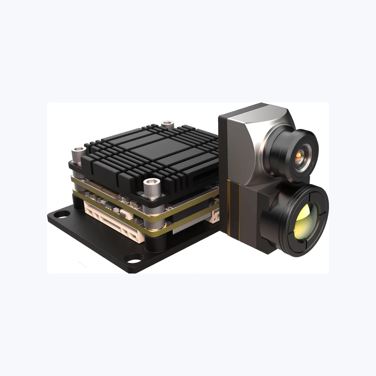
4 TOPS Dual-Spectrum UAV AI Tracking Module with 640×512 Thermal Camera (TC01-DUAL)
The TC01-DUAL is designed for SWaP-constrained micro-UAVs, tactical sub-kilo quadcopters, and compact robotic search units. Pairing a wide 109° HFOV visible sensor (2160×1440 at 60 Hz) with an uncooled 640×512 50 Hz LWIR core, it delivers broad situational scanning alongside clear thermal detection. The onboard 4 TOPS NPU tracks up to 60 targets simultaneously with an end-to-end latency around 30 ms. With a compact 38×38 mm mainboard and standard 25.5×25.5 mm mounting spacing, it drops directly into compact airframe bays without disrupting aircraft center-of-gravity.
View Product Details & Pricing ➔
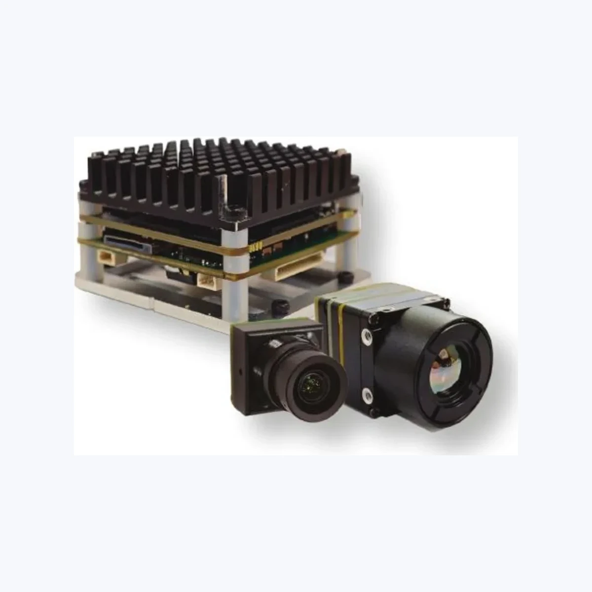
6 TOPS Dual-Spectrum UAV AI Tracking Module with 640×512 Thermal Camera (TM02-SOLO T)
The TM02-SOLO T is built for high-speed intercept airframes, tactical fixed-wing platforms, and perimeter security drones operating over larger areas. Driven by a 6 TOPS NPU and an Arm Cortex-A76/A55 heterogeneous CPU cluster, it pairs a fast 120 Hz 1080p visible camera with an uncooled VOx 640×512 50 Hz thermal core. It maintains active tracking locks on targets moving up to 450 km/h with an internal processing latency of just 8 ms. The tracking pipeline provides reticle locking, close-to-lock, route pre-mapping, and lost-target recall for up to 120 simultaneous tracks.
View Product Details & Pricing ➔
6. Engineering Selection Framework: Radiometric Payloads vs. Edge Tracking Modules
One common mistake in UAV procurement is confusing Radiometric Payloads with Edge-AI Tracking Modules. System architects must match the payload hardware to their primary operational mission.
| Architectural Attribute | Calibrated Radiometric Payload | Dual-Spectrum Edge-AI Payload |
|---|---|---|
| Primary Mission Objective | Precision absolute temperature measurement (°C/°F) | Target detection, classification, and tracking lock |
| Calibration Protocol | Multi-point blackbody calibration & atmospheric LUTs | High-speed Non-Uniformity Correction (NUC) |
| Output Data Stream | 14-bit/16-bit raw digital temperature arrays | Fused 8-bit video, bounding boxes, CRSF/MAVLink vectors |
| Onboard Compute Focus | Per-pixel emissivity and distance math | 4 to 6 TOPS INT8 deep learning neural networks |
| Primary Use Case Fit | Solar panel audits, high-voltage line inspection | Search & Rescue, perimeter security, tactical tracking |
When to Select a Calibrated Radiometric Core
Choose a radiometric thermal core when your mission requires certified, absolute surface temperature readings at every single pixel in the scene. Key operational examples include:
- ⚙️ Solar Farm Inspections: Locating defective sub-cell bypass diodes operating 15°C hotter than adjacent strings.
- ⚙️ Utility Grid Inspections: Measuring exact temperature rises on transformer bushings and high-voltage splices to spot impending failures.
- ⚙️ Building Envelope Audits: Quantifying thermal insulation breaks and structural moisture intrusion.
When to Select a Dual-Spectrum AI Tracking Module
Choose an onboard edge-AI tracking module—like the TC01-DUAL or TM02-SOLO T—when your operational objective requires rapid autonomous target acquisition, multi-object classification, and continuous tracking lock. While these modules deliver clean 640×512 thermal imaging, their processing is tuned for computer vision and dynamic tracking rather than absolute temperature metrology. They are ideal for:
- ✅ Search and Rescue (SAR): Sweeping open water or mountainous terrain at night, locking onto human thermal signatures, and centering the camera payload automatically.
- ✅ Perimeter & Asset Defense: Detecting human intruders and vehicles approaching secure boundaries and transmitting live tracking coordinates to flight controllers.
- ✅ Tactical UAV Tracking: Holding persistent visual lock on fast targets maneuvering up to 450 km/h through zero-lux environments and complex visual occlusions.
7. Frequently Asked Questions (Deep-Dive Technical FAQ)
Can modular thermal camera payloads be integrated into custom or open-source (ArduPilot/BetaFlight) drones instead of costly proprietary enterprise platforms?
They talk directly over standard serial protocols like CRSF and MAVLink, connecting straight to open-source flight controllers like Pixhawk running ArduPilot or STM32-based boards running BetaFlight. This setup lets drone builders deploy customized, secure, and cost-effective airframes with 640×512 thermal imaging and 4–6 TOPS onboard AI tracking—without recurring licensing fees or vendor lock-in.
What is the practical difference between radiometric thermal cameras and AI-assisted thermal tracking payloads for UAV operations?
AI-assisted tracking payloads, on the other hand, focus on relative thermal contrast, edge detection, and ultra-low latency. Instead of burning compute cycles calculating per-pixel temperatures, modules like the TC01-DUAL and TM02-SOLO T dedicate their 4 to 6 TOPS NPUs to running deep neural nets. They detect, classify, and track targets moving up to 450 km/h across dynamic environments—making them ideal for perimeter security, tactical tracking, and search and rescue.
How do you solve video latency and communication protocol bottlenecks when streaming thermal feeds from a UAV?
By placing a dual-spectrum module with an embedded 4 to 6 TOPS NPU right on the airframe, raw sensor streams are ingested locally over direct MIPI connections. The tracking engine executes detection, tracking, and fusion onboard in just 8 ms to 30 ms. The board drives the gimbal motors directly and streams small CRSF or MAVLink telemetry packets to the flight controller over hardware UARTs, ensuring deterministic target lock even if the video downlink suffers heavy packet loss.
📚 References & Further Reading
- Industry Standard: High-speed vision interface standards and digital video transmission protocols via the JIIA CoaXPress Certification Program.
- Aerospace Defense Engineering: Airborne thermal imaging, tactical reconnaissance, and optomechanical hardening standards from BAE Systems.
- High-Resolution Thermal Payloads: Explore megapixel LWIR capabilities with the HR-1280 1280×1024 Uncooled LWIR Thermal Imaging Module.
- OEM Procurement Guide: In-depth selection criteria for uncooled cores and optics via the Infrared Camera Module OEM Buying Guide.
- Tactical Handheld Systems: Ground observation and field target verification with the Handheld Infrared Thermal Observation Instrument.