Thermal Video Camera Cheap: The Engineer’s Guide to Low-Cost LWIR Cores
Thermal Video Camera Cheap: The Engineer’s Guide to Low-Cost LWIR Cores
For decades, getting your hands on a high-performance long-wave infrared (LWIR) imaging system meant blowing through defense-level capital budgets. If you did not have thirty grand to throw at a cryo-cooled sensor or a defense-grade assembly, you were locked out. Today, manufacturing breakthroughs in wafer-level packaging (WLP), 12-micrometer (μm) Vanadium Oxide (VOx) focal-plane arrays, and precision-molded chalcogenide optics have completely flipped the economics of thermal vision on its head. Finding a thermal video camera cheap enough for commercial original equipment manufacturer (OEM) integration no longer forces engineering teams to compromise on sluggish 9 Hz smartphone dongles or noisy, sub-par thermopile arrays. Full 640×512 resolution uncooled cores cranking out true 50 Hz frame rates are now readily available at price points that actually make sense for volume production across robotics, factory automation, process monitoring, and autonomous aerial platforms.
Here’s the deal, though: navigating the low-cost LWIR market requires a hard-nosed systems engineering approach. On paper, a camera core might look ridiculously cheap on your initial bill of materials (BOM). But that “bargain” sensor will blow up your lifecycle development budget if it drifts wildly inside unconditioned enclosures, lacks native embedded digital interfaces like MIPI-CSI2, or chokes incoming photon flux because the vendor cut corners with a cheap, high-F-number lens. Balancing thermal sensitivity (NETD), spatial resolution, Non-Uniformity Correction (NUC) algorithms, and edge-processing latency is the difference between shipping a rock-solid vision architecture and building a troubleshooting nightmare. This guide breaks down the microbolometer physics, optical trade-offs, interface protocols, and bench-tested integration strategies you need to select and deploy high-performance thermal video cameras without draining your project funds.
Table of Contents
- 👉 1. The Evolution of Low-Cost LWIR: VOx Microbolometers & Physics
- 👉 2. Frame Rates, Interface Latency, and the “Cheap Camera” Trap
- 👉 3. Optics Selection: Chalcogenide vs. Germanium & F-Stop Physics
- 👉 4. Module Showcase & Technical Specifications
- 👉 5. Edge AI & Dual-Spectrum Processing Pipelines
- 👉 6. Thermal and Electrical OEM Integration Guidelines
- 👉 7. Frequently Asked Questions (FAQ)
1. The Evolution of Low-Cost LWIR: VOx Microbolometers & Physics
Long-wave infrared detection operates squarely within the 8 to 14 μm atmospheric transmission window. In this band, we are measuring blackbody radiation emitted by all real-world objects above absolute zero according to Planck’s radiation law and the Stefan-Boltzmann law. Standard visible CMOS and CCD sensors rely on the photoelectric effect to kick electron-hole pairs loose from silicon semiconductor junctions. Thermal uncooled LWIR cameras do not work that way. Instead, they rely on microbolometer focal-plane arrays (FPAs). In an uncooled microbolometer, incoming thermal radiation strikes a tiny, suspended membrane, warming its micro-bridge structure and causing a measurable change in electrical resistance.
Historically, building these suspended micro-membranes with thermally isolated support legs was a brutal, low-yield process that required individual vacuum-sealed metal-can packaging. That packaging step alone used to drive costs through the roof. The real game-changer has been the rise of Wafer-Level Packaging (WLP). With WLP, hundreds of microbolometer dies are hermetically sealed in a deep vacuum simultaneously at the silicon wafer scale before dicing. That single process innovation caused yields to surge and unit costs to plummet, enabling hardware engineers to drop true 640×512 resolution cores into commercial designs where 160×120 sensors used to be the only affordable option.
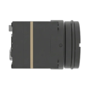
Vanadium Oxide (VOx) vs. Amorphous Silicon (α-Si)
When you are sourcing a core for an OEM system, the thin-film material used on that microbolometer membrane makes or breaks your system’s signal-to-noise ratio (SNR), thermal responsiveness, and baseline stability:
- ✅ Vanadium Oxide (VOx): In the shop, VOx is universally recognized as the undisputed champion for industrial and embedded thermography. It delivers a high Temperature Coefficient of Resistance (TCR of roughly 2% to 3%/K) alongside exceptionally low 1/f flicker noise. VOx sensors reliably hit Noise Equivalent Temperature Difference (NETD) ratings of ≤30 mK to 40 mK. That means your edge system preserves low-contrast thermal boundaries even in heavy fog, rain, or flat, low-delta-T environments.
- ⚙️ Amorphous Silicon (α-Si): While α-Si can be run through standard CMOS fab lines—which theoretically trims raw silicon manufacturing costs—it pays a heavy penalty in structural 1/f noise and a lower TCR. To keep the video from looking like static, α-Si cores lean heavily on aggressive spatial and temporal software filters. That digital smoothing causes noticeable motion ghosting and smears out subtle thermal gradients whenever the camera or target moves quickly.
Modern cost-optimized engineering heavily favors 12 μm pixel pitch VOx detectors. Transitioning from legacy 17 μm architectures down to 12 μm nodes cuts the overall physical die area by more than 50% for the exact same pixel count. That yield multiplier slashes wafer fabrication costs while simultaneously shrinking the required clear aperture of the front lens. The result? A much lighter optical BOM, smaller housing dimensions, and lower overall system weight. For a deeper look at how uncooled sensors are deployed in harsh field conditions, check out our field-tested breakdown on uncooled LWIR thermal modules for outdoor security and monitoring.
Non-Uniformity Correction (NUC) and Shutterless Operation
Because microbolometer pixels are notoriously sensitive, individual detector elements experience distinct gain and offset drift as the ambient enclosure heats up or cools down. Without correction, raw thermal frames quickly degrade into severe Fixed-Pattern Noise (FPN)—showing up as ugly vertical banding, screen grid artifacts, and heavy vignetting. The core’s Read-Out Integrated Circuit (ROIC) and embedded Image Signal Processor (ISP) apply a real-time two-point Non-Uniformity Correction (NUC) to calibrate individual pixel responses across the array.
Look, classic OEM cores handle this by dropping an electromechanical shutter blade in front of the array every few minutes to establish a uniform temperature baseline. While reliable, mechanical shutters bring moving parts that can wear out, make an audible clicking sound, and freeze your video output for 200 to 500 milliseconds. If you are tracking a dynamic target or running a closed-loop flight controller, that freeze frame can cause catastrophic tracking drops. Modern low-cost cores pair miniature electromagnetic solenoids with intelligent, scene-based shutterless NUC algorithms. These routines track substrate thermal changes via internal on-die thermistors, mathematically compensating for baseline offset drift without interrupting the live video feed—an absolute necessity for high-speed tracking and uninterrupted automated inspection.
2. Frame Rates, Interface Latency, and the “Cheap Camera” Trap
Engineers hunting for a thermal video camera cheap enough for rapid prototyping often get tempted by sub-$300 smartphone modules and consumer inspection dongles. While those gadgets work fine for checking insulation around a window, dropping them into an automated rig, robotic arm, or drone build is a recipe for failure. You run straight into two massive architectural brick walls: artificial frame-rate throttling and brutal interface latency.
The 9 Hz Export Bottleneck vs. 50/60 Hz High-Speed Cores
Under international export control frameworks—namely the Wassenaar Arrangement and US EAR/ITAR export regulations—thermal cameras running at refresh rates above 9 Hz face tight dual-use controls. To sell consumer hardware globally with zero paperwork, consumer thermal manufacturers artificially cap their sensor readout or USB bridge to a sluggish 8.7 to 9.0 Hz.
In the real world of industrial robotics, automated optical inspection (AOI), or UAV tracking, 9 Hz is completely useless. Consider a target moving at a modest 36 km/h (10 m/s). Between consecutive frames on a 9 Hz camera, that target moves over 1.1 meters. That massive temporal blind spot causes proportional-integral-derivative (PID) tracking loops to overshoot, oscillate, and drop tracking locks entirely. High-performance industrial cores like the MD-64CA output a true native 50 Hz refresh rate (delivering a clean new frame every 20 milliseconds), giving your compute hardware the temporal fidelity needed for fast closed-loop motion control and rock-solid tracking.
Hardware Interface Protocols: MIPI-CSI2, USB UVC, and CVBS
Moving thermal pixel streams from the sensor ROIC into your host application processor requires picking the right electrical bus. You have to balance processing overhead, cabling flexibility, and latency:
| Interface Protocol | Typical Latency | Host CPU Overhead | Primary Integration Fit |
|---|---|---|---|
| MIPI-CSI2 | <10–15 ms | Minimal (DMA direct to RAM) | Embedded Linux SoCs, NVIDIA Jetson, Edge AI inference boards. |
| USB UVC (Type-C) | 30–60 ms | Moderate (Kernel USB stack) | Rapid PC prototyping, ROS2 nodes, cross-platform host software. |
| CVBS (Analog Baseband) | <5 ms | Zero (Direct DAC to transmitter) | Long-range RF video transmitters, FPV pilot monitoring, legacy displays. |
Running raw 14-bit thermal video through MIPI-CSI2 pipes data straight into the host processor’s RAM via Direct Memory Access (DMA). This bypasses the multi-layer protocol stack and variable frame jitter inherent to USB drivers, making native MIPI the runaway favorite for zero-latency, time-critical embedded vision.
3. Optics Selection: Chalcogenide vs. Germanium & F-Stop Physics
In standard visible cameras, lenses are pressed from inexpensive crown or flint silica glass. But across the 8 to 14 μm LWIR spectrum, everyday glass acts like a solid brick wall. Infrared photons cannot pass through it. Thermal optics require specialized materials, which traditionally accounted for up to 60% of the entire camera’s production cost.
Chalcogenide Glass Molding vs. Single-Crystal Germanium
Single-crystal Germanium (Ge) offers an exceptionally high refractive index (n ≈ 4.0), making it great for designing thin, compact lenses with minimal chromatic aberration. But raw Germanium is scarce, exposed to volatile global supply chains, and must be shaped using Single-Point Diamond Turning (SPDT)—a slow, precision-lathe operation that scales terribly for mass production.
To slash BOM costs without tanking image quality, modern production cores utilize precision-molded Chalcogenide glass (amorphous alloys composed of selenium, sulfur, tellurium, and germanium). Chalcogenide glass softens at manageable temperatures, allowing high-precision compression molding in multi-cavity tooling. This yields complex, high-performance aspheric optical elements in high volumes, driving optical fabrication costs down by 40% to 60%. Even better, Chalcogenide glass has a much lower thermal change in refractive index (dn/dT) than Germanium. This property makes it far easier to engineer passively athermalized lens assemblies that stay laser-sharp from -20 °C up to +60 °C without heavy, motorized focus rings.
The Critical Physics of Lens Aperture (F-Stop)
Here is where rookie system designers get caught off guard: in the thermal realm, the total infrared radiant flux ($\Phi$) landing on the focal plane scales inversely with the square of the optical F-number:
If you switch from a fast F/1.0 aperture down to a cheaper, smaller F/1.4 lens assembly, the thermal energy hitting your detector array drops by roughly 51%:
To compensate for losing half your photon flux, the ISP has to crank the analog gain, pushing the noise floor through the roof. A top-tier VOx sensor rated at an NETD of ≤30 mK behind an F/1.4 lens instantly degrades to an effective ≥60 mK system. Those crisp thermal gradients and low-contrast edge signatures disappear in a sea of digital noise. Industrial-grade low-cost modules stick strictly to fast F/1.0 glass across all standard focal lengths (from 4.9 mm wide angles to 35 mm telephotos) to keep your thermal sensitivity intact.
4. Module Showcase & Technical Specifications
To help you pick the right hardware for your setup, let’s take a deep look at two production-ready platforms that balance low cost with industrial-grade reliability: the dedicated MD-64CA uncooled VOx imaging core and the all-in-one TM02-SOLO T dual-spectrum AI tracking module.
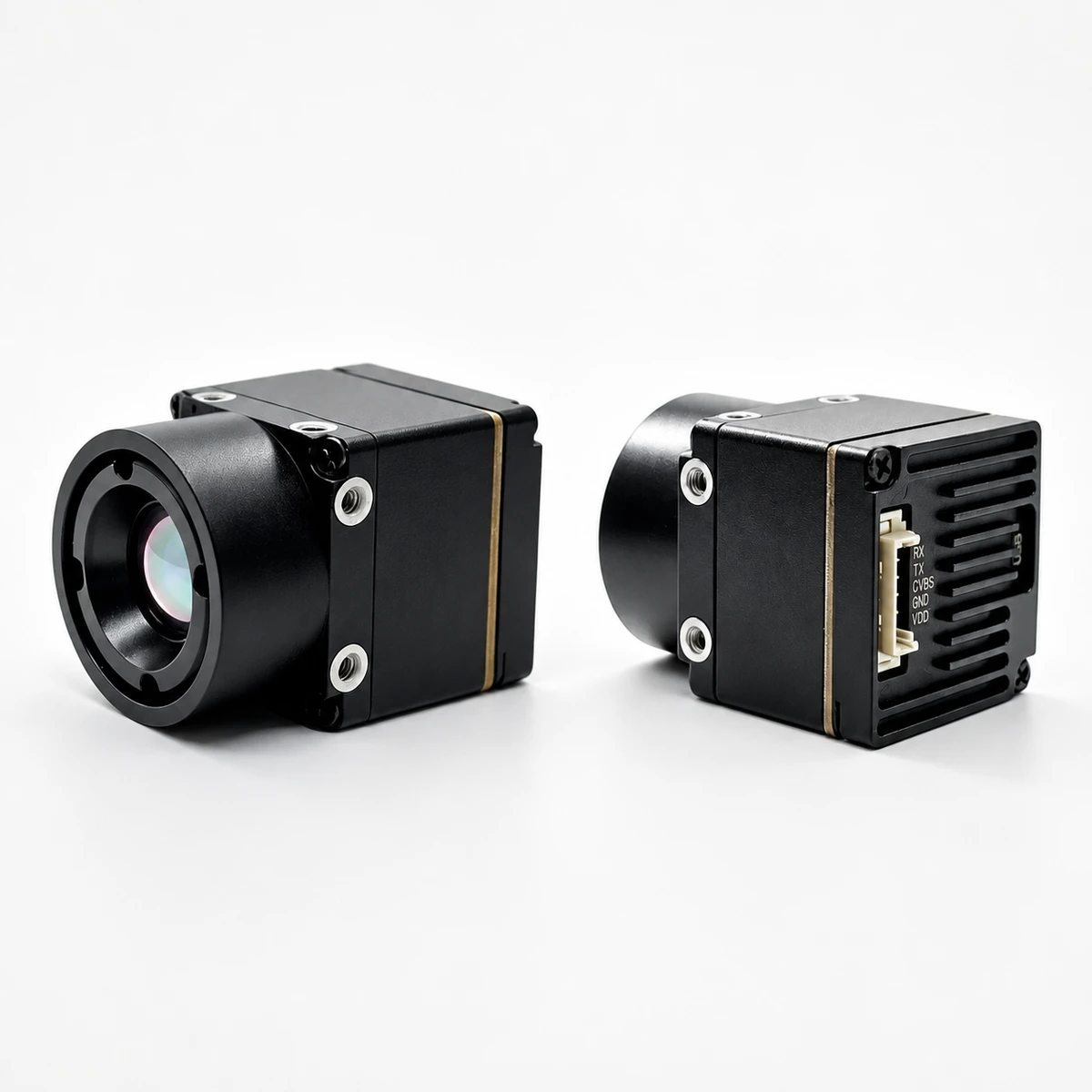
MD-64CA 640 x 512 Uncooled VOx Thermal Imaging Camera Module
The MD-64CA is an ultra-compact, featherweight LWIR core built from the ground up for embedded machine vision, OEM integrations, robotics, and small UAV payloads. Packing a 640×512 uncooled VOx focal-plane array with a tight 12 μm pixel pitch, this module delivers silky-smooth 50 Hz real-time thermal video while consuming under 0.7 W of power.
Weighing in at just 23.1 grams, the module features multi-protocol output flexibility—handling raw 14-bit digital MIPI-CSI2, standard plug-and-play USB UVC, and analog CVBS for zero-latency long-range RF downlinks. The MD-64CA runs across a wide input voltage range from 5 to 24 V DC, simplifying power distribution on drone battery buses or industrial rails. You can configure it with factory-aligned F/1.0 optics ranging from a wide 4.9 mm (76.2° HFOV) to a narrow 35 mm telephoto (12.5° HFOV).
| Model Designation | MD-64CA |
|---|---|
| Detector Architecture | Uncooled Vanadium Oxide (VOx) Focal-Plane Array |
| Array Resolution | 640 × 512 pixels |
| Pixel Pitch & Spectral Band | 12 μm | 8 to 14 μm (LWIR) |
| Thermal Sensitivity (NETD) | ≤30 mK (@ 25 °C, F/1.0) |
| Frame Refresh Rate | 50 Hz (Real-Time Video Output) |
| Standard Optical Options | 4.9 mm (76.2°×64.2°), 9.1 mm (45.8°×37.3°), 13 mm (33.0°×26.6°), 19 mm (22.9°×18.4°), 35 mm (12.5°×10.0°) — All F/1.0 |
| Host Interface Options | Digital MIPI-CSI2, USB UVC, Analog CVBS |
| Operating Voltage & Power | 5.0 to 24.0 V DC | <0.7 W steady state |
| Weight & Operating Temp | 23.1 g (Base Core) | -20 °C to +60 °C |
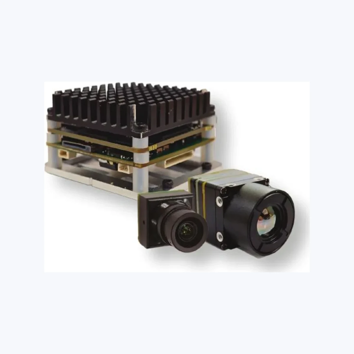
TM02-SOLO T: 6 TOPS Dual-Spectrum UAV AI Tracking Module
The TM02-SOLO T integrates a high-speed electro-optical (EO) visible daylight camera and a 640×512 uncooled VOx thermal sensor on a single 6 TOPS edge-AI compute board. Engineered for UAV integrators and autonomous vehicle developers, it provides automated target acquisition, classification, and continuous tracking across full sun, thick haze, and complete darkness.
The onboard heterogeneous compute engine pairs dual Arm Cortex-A76 cores (2.4 GHz) and quad Cortex-A55 cores (1.8 GHz) with a dedicated Neural Processing Unit (NPU). It runs deep-learning multi-target tracking pipelines at an ultra-low inference latency of just 8 ms. This enables steady tracking locks on moving vehicles out to 400 meters and human targets out to 170 meters, even at high engagement speeds up to 450 km/h. It supports simultaneous Picture-in-Picture (PIP) and visible-thermal fusion modes, communicating natively with BetaFlight and ArduPilot autopilots using the CRSF telemetry protocol.
| Model Designation | TM02-SOLO T |
|---|---|
| AI Acceleration & CPU | 6 TOPS NPU | Arm Cortex-A76 (2.4 GHz) + Cortex-A55 (1.8 GHz) |
| Visible (EO) Optical Sensor | 1/1.8″ Sensor | 1920×1080 @ 120 Hz | 0.001 lux Low-Light Sensitivity |
| Thermal (LWIR) Sensor | 640×512 Uncooled VOx | 12 μm Pitch | 50 Hz | 9.1 mm Lens (47.7°×38.2°) |
| Tracking Performance | Vehicle: 400 m | Person: 170 m | 8 ms Processing Latency | Up to 120 Tracks |
| Autopilot & Control Protocol | CRSF Protocol | Native BetaFlight & ArduPilot Compatibility |
| Supply Voltage & Form Factor | 9.0 to 16.0 V DC Regulated | Board: 45 × 45 × 26 mm (42.5 mm mounting) |
If your project calls for a ruggedized, ready-to-use handheld system for field spot checks or ground inspection, take a look at the IP67-rated handheld infrared thermal observation instrument, which uses the same proven 12 μm VOx technology.
5. Edge AI & Dual-Spectrum Processing Pipelines
Deploying a low-cost LWIR camera onto autonomous Unmanned Aerial Vehicles (UAVs) or automated guided mobile robots (AMRs) usually means pairing thermal imaging with a high-definition visible camera. Visible sensors pull crisp high-frequency textures and true color signatures under bright lighting, but turn completely blind the moment smoke, heavy dust, or total darkness rolls in. Thermal cameras cut right through obscurants based on pure radiated heat, but they lack fine surface markings and readable signage. Blending both data streams gives your perception stack unbeatable reliability across all operating conditions.
Deep Learning Pipelines on 14-Bit Thermal Streams
Deploying models like YOLOv8-nano or MobileNet-SSD straight onto raw thermal frames requires some smart data preprocessing on your embedded host. Off-the-shelf neural networks trained on 8-bit RGB datasets fail when you feed them raw, single-channel 14-bit integer values straight from a microbolometer ADC without proper normalization.
Here is how to set up an optimized inference pipeline using runtime engines like TensorFlow Lite or TensorRT on embedded hardware:
- ⚙️ Dynamic Range Compression: Take the incoming 14-bit digital stream (0 to 16,383 discrete levels) and run it through a Digital Detail Enhancement (DDE) and Contrast Limited Adaptive Histogram Equalization (CLAHE) stage. This pulls out edge details and compresses the scene into an 8-bit range without blowing out hot spots.
- ⚙️ INT8 Quantization: Quantize your network weights from FP32 down to INT8 using a representative calibration dataset of thermal images. Running INT8 inference unleashes the full speed of hardware accelerators (like the 6 TOPS NPU on the TM02-SOLO T), dropping execution times below 10 ms per frame.
- ⚙️ Direct Tracking Feedback: Pipe the output bounding-box coordinates directly into your flight stack or motion controller via MAVLink or CRSF telemetry. This gives your gimbal or drive platform instant, closed-loop tracking response. For more aerial integration architectures, review our field guide on drone thermal camera applications.
6. Thermal and Electrical OEM Integration Guidelines
Integrating a bare OEM thermal core into a custom enclosure is where bench prototypes either succeed or fail. Microbolometers are exceptionally sensitive analog devices; dirty power rails or sloppy mechanical heat dissipation will ruin your image before you even write your first line of application code.
Power Supply Conditioning and Ripple Rejection
The analog front end and ROIC inside a thermal core operate at ultra-low signal levels. Any high-frequency switching noise coming from nearby brushless motor Electronic Speed Controllers (ESCs), switching buck converters, or noisy digital buses will bleed into the analog readout, causing horizontal lines, rolling hum bars, or herringbone patterns across the video.
- ⚙️ Power Rail Ripple Budget: Keep total DC supply ripple below 20 mVp-p at the camera connector. Use a dedicated low-dropout (LDO) linear regulator or an LC filter right at the module’s DC input pins to clean up switching spikes.
- ⚙️ Startup Inrush Tolerances: While steady-state power draw on cores like the MD-64CA sits under 0.7 W, the ROIC and internal startup routines draw brief inrush current spikes during power-on and shutter cycles. Make sure your power supply can source up to 2.0 A peak pulses at 5 V without dropping out or dipping below the minimum voltage rail.
Thermal Dissipation and Structural Isolation
Uncooled microbolometers do not use active cryogenic chillers, but their measurement accuracy depends completely on uniform temperature distribution across the camera chassis. If one side of your camera housing heats up faster than the other, your internal calibration lookup tables go out the window, leading to severe spatial drift and fixed-pattern distortion.
- ⚙️ Establish a Solid Conduction Path: Avoid mounting thermal cores inside completely sealed plastic boxes with dead air pockets. Bolt the module’s aluminum chassis directly to your main metal enclosure or frame using a thermal interface pad (TIM) rated for a conductivity of k ≥ 3.0 W/m·K.
- ⚙️ Shield from Hot Components: Keep the thermal core physically isolated from major heat generators like multicore application SoCs, motor drivers, and RF power amplifiers. If space is tight, insert a grounded aluminum or copper heat shield between the hot board and the camera body to eliminate uneven radiant heating across the sensor array.
7. Frequently Asked Questions (FAQ)
Why do cheap thermal video cameras suffer from severe lag and motion blur?
Are sub-$400 256×192 thermal cameras worth it for engineering projects compared to 640×512 cores?
What are the critical trade-offs when selecting a low-cost thermal module for OEM integration?
- Optical Speed vs. Physical Envelope: Fast F/1.0 optics maximize photon collection and preserve sensor sensitivity (NETD ≤30 mK), but require larger lens diameters compared to slower F/1.2 or F/1.4 alternatives.
- Interface Complexity vs. Compute Latency: Native MIPI-CSI2 provides the lowest processing latency and bypasses USB buffering, but requires developing kernel-level device drivers for the host SoC.
- Power Dissipation vs. Sensor Drift: Ultra-low-power cores (<0.7 W) simplify thermal management in sealed enclosures, whereas modules with integrated AI NPUs require conductive mechanical coupling to prevent internal heat buildup.
- Pixel Pitch vs. Optical BOM: Modern 12 μm pixel arrays allow the use of smaller, molded chalcogenide lenses, reducing total system weight and BOM cost compared to older 17 μm architectures.
- NUC Architecture: Shutterless systems eliminate moving parts and audible clicks, but rely on robust algorithms and stable host thermal management to prevent fixed-pattern drift.
📚 References & Further Reading
- Industry Standard: Wikipedia – Unmanned Aerial Vehicle
- Machine Learning Framework: TensorFlow Open Source Machine Learning Platform
- Related Guide: Uncooled LWIR Thermal Modules for Outdoor Security & Monitoring
- System Architecture: Drone Thermal Camera Integration and Edge Applications
- Field Instruments: Handheld Infrared Thermal Observation Instrument Specifications