Engineering tool · Timing scenarios
Use the Thermal Video Continuity Calculator to compare interruption scenarios—not actual dropped frames. Both examples are hypothetical.
Compare two capture scenarios
Your modeled comparison
Scenario A
Scenario B
Blue: modeled observable time. Sand: affected time. Bar proportions are not a timeline of individual events.
| Metric | A | B |
|---|---|---|
| Affected time (s) | — | — |
| Observable time (%) | — | — |
| Affected scene-sample equivalents | — | — |
| Average observable sampling budget (samples/s) | — | — |
| Interruption event count | — | — |
| Longest continuous unobserved interval (s) | — | — |
Scene-sample equivalents may be fractional. They are not actual dropped frames. A frozen image may repeat old frames while transport continues. Observable-time percentage is a property of this timing model, not measured system availability; the sampling budget is not transport fps.
Use the Thermal Video Continuity Calculator
Start with the observation window you want to evaluate. Enter its duration in seconds and the sampling frequency appropriate to that capture plan. If the frequency is a planning assumption rather than a verified host capture rate, keep both scenarios labeled hypothetical. A detector specification alone is not evidence of a particular USB capture mode.
Set P to the time between interruption starts. Set d to the duration of each interruption in whole milliseconds. Set a to the first interruption’s start time relative to capture start. A and B have independent P, d and a values; changing one scenario does not silently change the other.
The initial Thermal Video Continuity Calculator example uses 600 seconds and a hypothetical 50 samples/s for both scenarios. A assumes a 200 ms interruption starting every 60 seconds, first at 60 seconds. B assumes 100 ms with the same starts. Neither example represents HI640, Boson or another camera’s measured behavior.
Results update as you edit. The Calculate comparison button also validates the form and focuses the first invalid input. Reset restores the hypothetical examples, including their source labels. Invalid or incomplete inputs hide the results so that an old valid result is not mistaken for the current calculation.
Timing formulas and boundary rules
The Thermal Video Continuity Calculator uses integer milliseconds. Let t = round(1,000T), p = round(1,000P), aMs = round(1,000a) and b = round(d). Capture occupies the half-open interval [0, t): an interruption beginning exactly at t is not counted. The final interruption is clipped at the end of the window.
If b = 0 or aMs ≥ t: N = B = longest = 0.
Otherwise:
N = floor((t − 1 − aMs) / p) + 1
tail = t − (aMs + (N − 1) × p)
B = (N − 1) × b + min(b, tail)
longest = b = p ? t − aMs : N > 1 ? b : min(b, tail)
N is the count of interruption starts that affect the window; B is affected milliseconds. Because d cannot exceed P, intervals cannot overlap. When b equals p, consecutive intervals touch and form one continuous unobserved interval. That is why longest can exceed the duration of an individual event.
- Affected time: B / 1,000 seconds.
- Observable-time percentage: 100 × (t − B) / t.
- Affected scene-sample equivalents: f × B / 1,000.
- Average observable sampling budget: f × (t − B) / t samples/s.
T and P accept 0.001–86,400 seconds; a accepts 0–86,400 seconds. These fields allow at most three decimal places. Frequency accepts 0.1–1,000 samples/s. Duration accepts whole milliseconds from zero to the smaller of 60,000 and p. Blank, non-finite, out-of-range and invalid decimal inputs are rejected rather than silently corrected.
In the default A example, the starts occur at 60 through 540 seconds: nine events, 1.8 seconds affected, 99.7% modeled observable time, 90 scene-sample equivalents and a 49.85 samples/s average observable budget. These are arithmetic outputs from hypothetical inputs, not a hardware test.
Read the results without overclaiming
Use the Thermal Video Continuity Calculator to compare timing assumptions, not to certify a stream. Scene-sample equivalents describe how much sampling opportunity falls within affected time. They can be fractional because the model integrates duration; it does not align every exposure or count frames from a recording.
A receiver can keep delivering repeated frames during a frozen scene. Conversely, a transport may drop or delay frames outside the interruptions you entered. The observable sampling budget is therefore not the negotiated frame rate, measured throughput or verified fresh-scene rate. An event count also says nothing about its underlying cause.
A zero result means only that the entered component assumptions contribute no affected time within this window. It does not establish 100% system availability. If you enter d = 0 for B, that remains your assumption; the tool does not assign a zero pause to any shutterless product.
The regular-event model does not describe random outages, variable-duration corrections, overlapping causes, scene-to-host latency or temperature drift. It does not calculate FOV, DRI range, radiometric accuracy or calibration quality. For irregular interruptions, analyze the actual timestamped record rather than replacing it with a single average and calling the result a measurement.
For a meaningful A/B comparison, keep the observation window and sampling plan unchanged, then change only the interruption assumptions you intend to compare. Preserve the units and source of each input in your engineering record. “User-measured” is a self-declared label, not independent verification by CAMCUDA.
Why mechanical shutterless design matters
A mechanical correction flag can temporarily interrupt observation of the scene while a reference is acquired. Removing that component addresses one mechanism; it does not remove every reason that images might repeat, arrive late or stop. Algorithmic correction, startup calibration, the interface, host software and operating conditions still need evaluation.
The older Boson FFC explanation describes a frozen video interval during its specified mechanical process. That historical product-specific timing is not used as a default or transferred to HI640 or current competing models.
The Tenum 640 Echo datasheet describes an initial NUC at power-up followed by continuing shutterless correction. This supports the distinction between shutterless construction and absence of correction—not an assumption that every camera has the same startup sequence.
HI640 lists shutterless NUC. Treat that as a component and correction description, not a guarantee of uninterrupted host capture or calibrated temperature output. Our shutterless thermal module comparison separates configuration scope, interfaces and published specification limits.
HI640 integration: six clear checks
- Interface hardware: identify the delivered board, connector, supply and electrical levels. An interface name does not specify every accessory or host requirement.
- Host capture contract: obtain supported resolution, pixel format and capture rate for your host. HI640’s 50 Hz detector rate is not a verified 50 fps USB mode.
- Fresh-scene evidence: use a controlled moving thermal stimulus with timestamps and repeat-frame analysis. Identical pixels in a static scene alone do not prove freezing; changing noise alone does not prove fresh sampling.
- Startup: record behavior from power-up through normal operation. Separate time to first image from the interruption duration entered in this calculator.
- Thermal conditions: test correction and drift across the intended operating conditions. The timing model does not predict either drift or image quality.
- Radiometry: HI640’s published measurement range and calibrated accuracy are not established. Obtain documented capability and compensation requirements before planning quantitative temperature measurements.
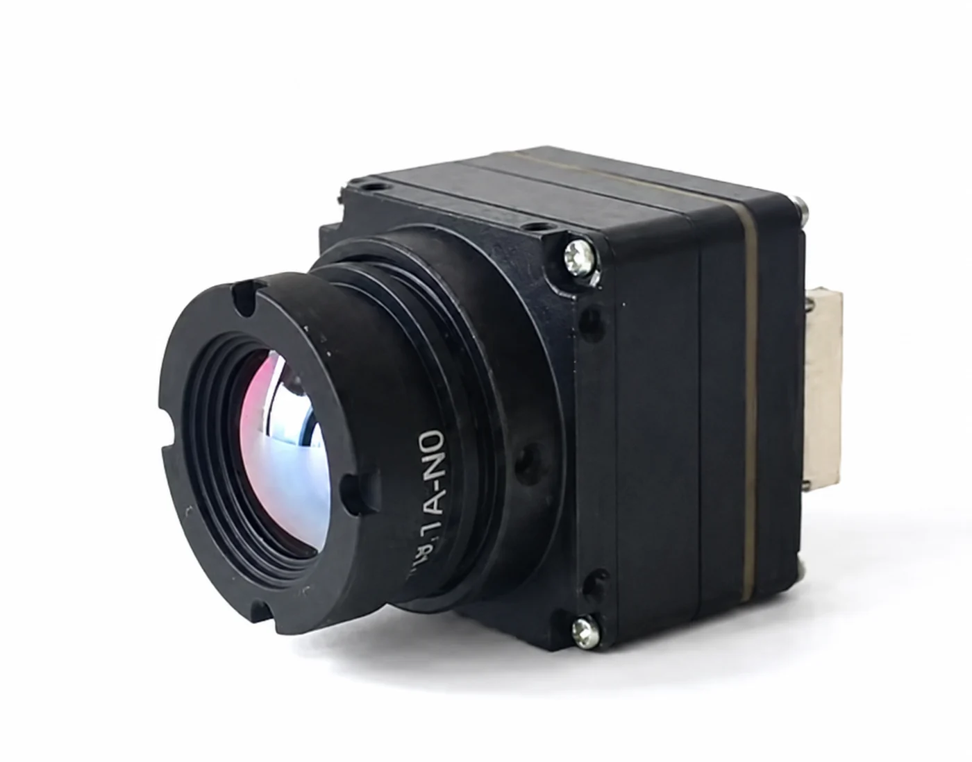
After using the Thermal Video Continuity Calculator, share your lens, host, interface, capture format and quantity for a configuration-specific enquiry. Review the current product documentation and sample options before selecting a module.
Review HI640 & request a configuration quoteThermal Video Continuity Calculator FAQ
Does this calculator count actual dropped frames?
No. It computes affected scene-sample equivalents from your frequency and interruption duration. A frozen stream may repeat old images without transport drops. Actual dropped, repeated or delayed frames require analysis of the captured stream and timestamps.
Are the default scenarios measured HI640 results?
No. Both are hypothetical, including the example 50 samples/s. The user-measured label is your statement only. Verify the capture format and rate on your host; do not substitute the detector frame rate for a measured USB rate.
Does shutterless mean zero interruptions or calibrated temperature?
No. Mechanical shutterless design does not remove startup calibration, algorithmic correction, host or transport interruptions, drift or latency. It also does not establish radiometry. A zero-duration input models your component assumption, not guaranteed system availability.
What happens at the end of the capture window?
An event starting exactly at T is excluded. An earlier event is clipped at T. When the interruption duration equals its start interval, touching events form a continuous unobserved interval; the tool reports that combined longest interval.