640×512 15 mm FOV: Why Thermal Camera Specs Differ
Why does a 640 × 512 thermal camera with a 15 mm lens sometimes list a field of view of 28.72° × 23.15°, while another table gives 29.34° × 23.47°? With 12 μm pixels, the two pairs can come from two different calculations: a rectilinear optical model and a small-angle approximation.
THERMAL CAMERA OPTICS EXPLAINED
One sensor size. Two ways to calculate the angle.
The difference is about 0.62° horizontally and 0.32° vertically. Understanding where those numbers come from makes it easier to compare lens specifications—and to recognize when the calculation alone cannot explain a datasheet.
Start with the detector, not just “640”
Pixel count and pixel pitch together determine the active-array dimensions used in the calculation. For a full 640 × 512 array with square 12 μm pixels:
12 μm = 0.012 mm
Width = 640 × 0.012 = 7.68 mm
Height = 512 × 0.012 = 6.144 mm
Here, FOV means the full angular field, written as horizontal × vertical. A diagonal angle is a different quantity. We assume the full array is used, the lens follows an ideal rectilinear projection and the focus is at a distant scene. Cropped output and real lens distortion need separate treatment.
“640” alone is insufficient. A 640 × 512 array with 8 μm pixels is only 5.12 × 4.096 mm. Paired with the same hypothetical 15 mm rectilinear lens, it would calculate to approximately 19.37° × 15.55°. That is a different detector size, rather than a rounding difference.
Why the two formulas give different answers
1. The rectilinear arctangent formula
For an ideal rectilinear lens, the image height follows the tangent of the off-axis angle. For a sensor dimension d and focal length f:
FOV = 2 × arctan(d ÷ (2f))
HFOV = 2 × arctan(7.68 ÷ 30) = 28.718673…°
VFOV = 2 × arctan(6.144 ÷ 30) = 23.148258…°
Rounded to two decimal places: 28.72° × 23.15°.
This is the standard angular-FOV relation described in Edmund Optics’ explanation of focal length and field of view. It is an ideal geometry calculation, not a measurement of a particular lens.
2. The small-angle linear approximation
When an angle is sufficiently small, its tangent is close to the angle itself, expressed in radians. Replacing the arctangent relation with that approximation gives:
FOV ≈ (d ÷ f) × (180 ÷ π)
HFOV ≈ (7.68 ÷ 15) × (180 ÷ π) = 29.335439…°
VFOV ≈ (6.144 ÷ 15) × (180 ÷ π) = 23.468351…°
Rounded to two decimal places: 29.34° × 23.47°.
Rounded to one decimal place: 29.3° × 23.5°.
The larger pair is therefore consistent with a linear approximation. In this example it exceeds the rectilinear result by 0.616766° horizontally and 0.320094° vertically, or about 2.15% and 1.38% of the respective rectilinear angles.
Where IFOV enters the calculation
Near the optical axis, the pixel-angle estimate is IFOV ≈ pixel pitch ÷ focal length. Here, 0.012 ÷ 15 = 0.0008 radians, or 0.8 mrad per pixel. The IRCameras IFOV calculator documents the pitch-over-focal-length relationship.
Multiplying 0.0008 radians by 640 or 512 produces the linear FOV estimate above. For a rectilinear lens, however, angular spacing per pixel varies across the image. Multiplying a near-axis estimate by the full pixel count does not reproduce the full arctangent field exactly.
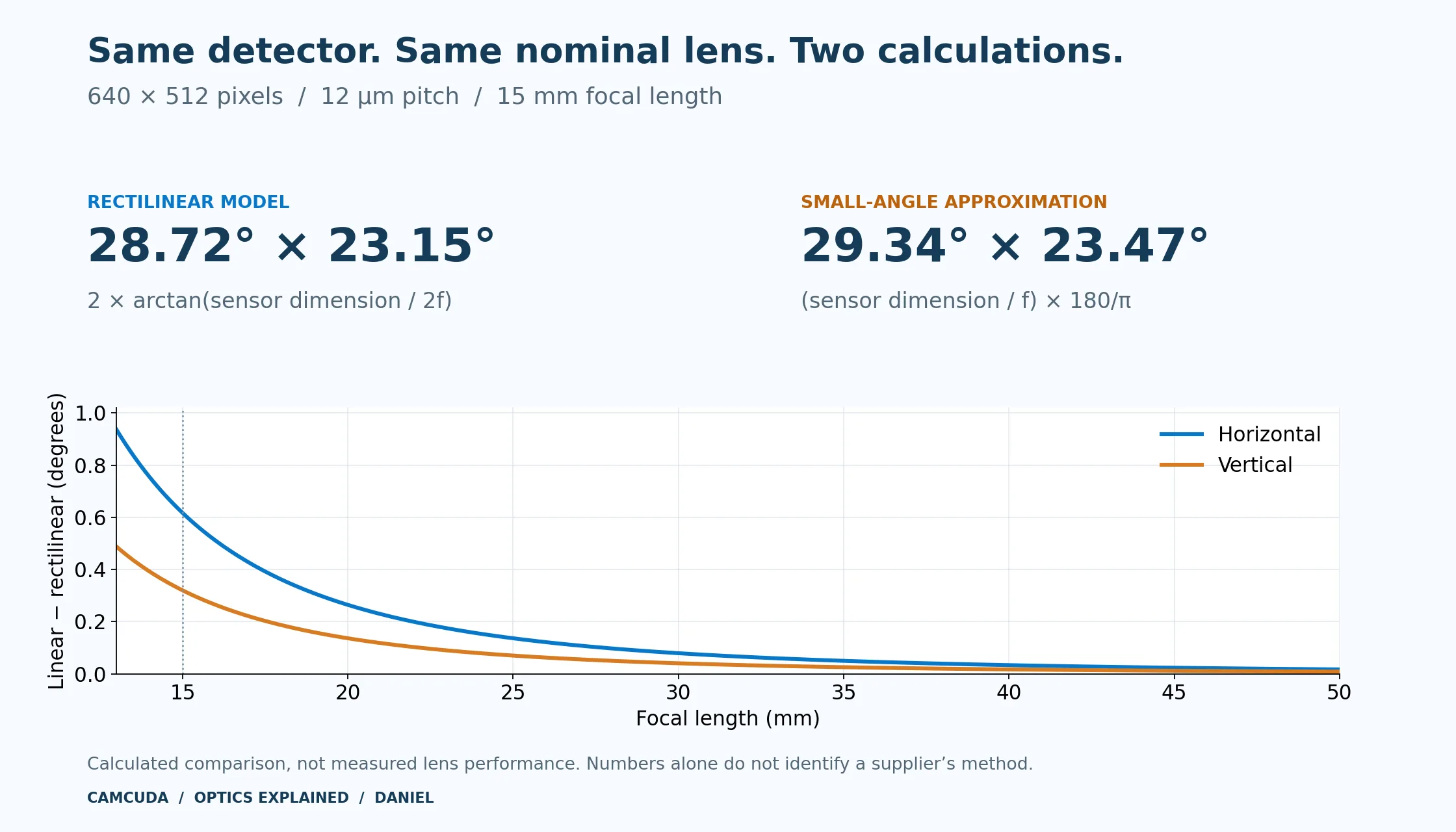
How much does the approximation change with focal length?
The same two calculations can be repeated without changing the detector. Each entry below is calculated from a 7.68 × 6.144 mm active array; none is presented as a supplier’s measured specification.
| Focal length | Rectilinear H × V | Linear approximation H × V | Difference H / V |
|---|---|---|---|
| 13 mm | 32.91° × 26.59° | 33.85° × 27.08° | +0.936° / +0.488° |
| 15 mm | 28.72° × 23.15° | 29.34° × 23.47° | +0.617° / +0.320° |
| 18 mm | 24.09° × 19.37° | 24.45° × 19.56° | +0.361° / +0.187° |
| 25 mm | 17.46° × 14.01° | 17.60° × 14.08° | +0.136° / +0.070° |
| 35 mm | 12.52° × 10.03° | 12.57° × 10.06° | +0.050° / +0.026° |
| 50 mm | 8.78° × 7.03° | 8.80° × 7.04° | +0.017° / +0.009° |
As focal length increases, the sensor occupies a smaller angle and the approximation becomes closer. At 35 mm, the horizontal difference is still about 0.050°; at 50 mm, it is about 0.017°. Whether that matters depends on the precision and coverage margin required.
A matching 15 mm row does not identify the method used for an entire lens table. For example, a quoted 13 mm value of 31.9° × 25.7° matches neither the ideal 32.91° × 26.59° nor the linear 33.85° × 27.08° result for this detector. Check each row against its own optical specification.
What a calculation can—and cannot—tell you about a real lens
The numerical agreement explains how the two 15 mm pairs can arise. It does not prove which method an unnamed manufacturer used. The supplier may be reporting a nominal calculation, a lens-design value, a calibrated camera value or a field measured in a particular output mode.
Nominal focal length and effective focal length
“15 mm” is a nominal lens designation. The design’s effective focal length and its manufacturing tolerance belong to that lens specification. There is no basis here to assign every thermal lens a universal ±3–5% tolerance.
It is also worth checking both axes before explaining the larger pair as a shorter focal length. Rearranging the rectilinear equation gives f = d ÷ [2 × tan(FOV ÷ 2)]. With this detector, 29.34° horizontally implies approximately 14.6685 mm, while 23.47° vertically implies approximately 14.7886 mm. A single shorter focal length does not reproduce both supplied angles exactly in the same distortion-free model.
Distortion and image processing
Real lenses can map off-axis rays differently from an ideal rectilinear model. Edmund Optics’ distortion guide explains how image magnification varies across the field and why distortion depends on the optical design. A lens-specific distortion curve is more useful than assuming a percentage from its F-number.
Cropping, digital zoom and distortion correction can also change the field delivered to the host. Ask whether a quoted FOV describes the raw full detector, a corrected image or a particular cropped output. Neither formula measures these effects by itself.
A wider quoted FOV does not establish a defective lens, a better lens or identical hardware. Confirm the detector, lens revision, output mode and measurement basis before drawing those conclusions.
What the difference means at a working distance
For an ideal rectilinear view of a plane perpendicular to the optical axis, scene width is 2 × distance × tan(HFOV ÷ 2). Use vertical FOV for scene height.
At 100 m, the unrounded rectilinear angles in this example give a scene about 51.20 m wide × 40.96 m high. If the linear angle estimates are instead entered as rectilinear angles in that coverage formula, the result is about 52.35 m × 41.54 m.
That is a difference between calculation conventions, not additional scene coverage demonstrated by a camera. Use the confirmed camera field and an appropriate projection model when planning overlap, inspection coverage or calibration. Angular FOV alone does not establish detection range or temperature-measurement accuracy.
Apply the same checks to CAMCUDA camera modules
The product lens table is the starting point for choosing an optical assembly. A nominal focal length is useful for identifying a configuration; the published FOV and the confirmed delivered image define the coverage you should evaluate.
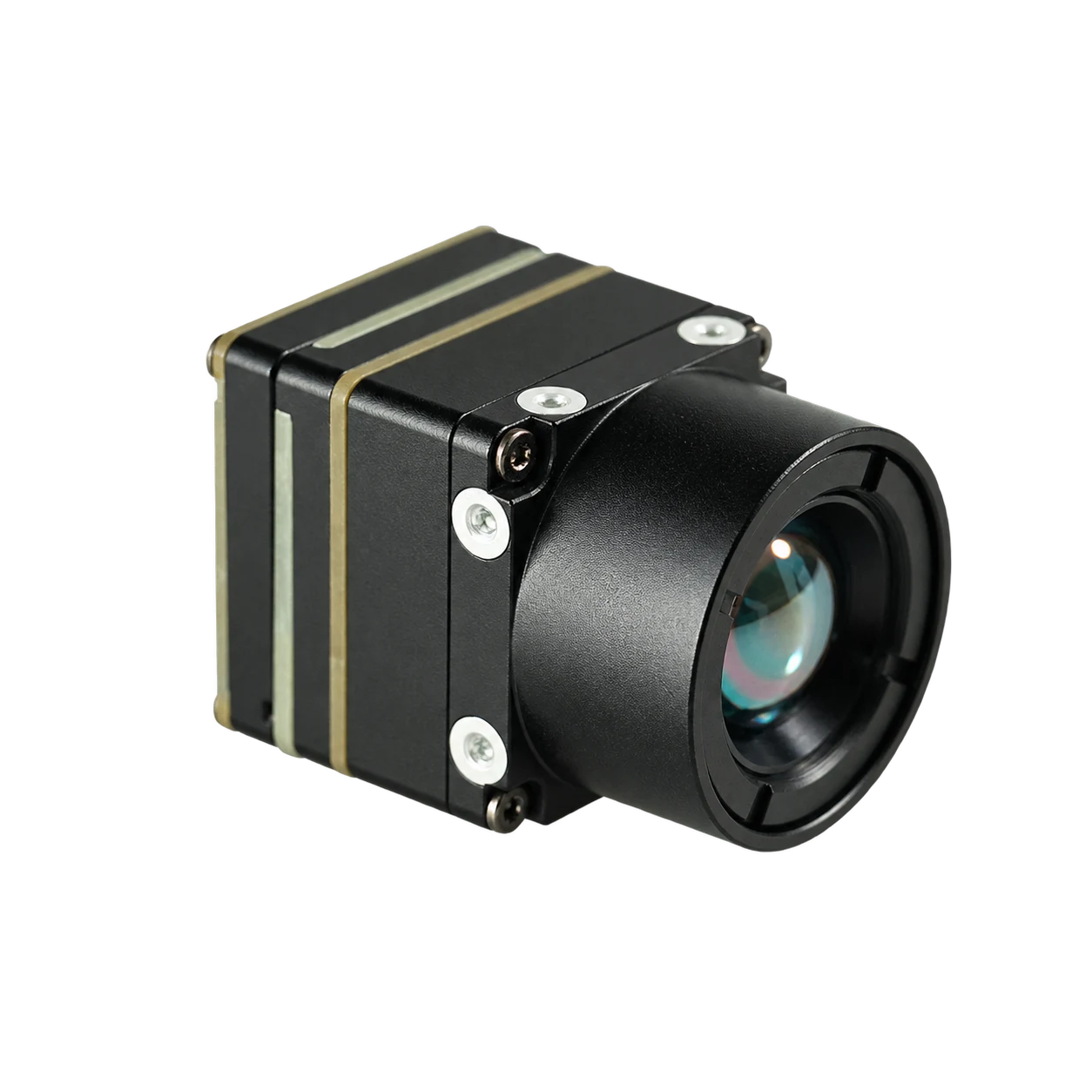
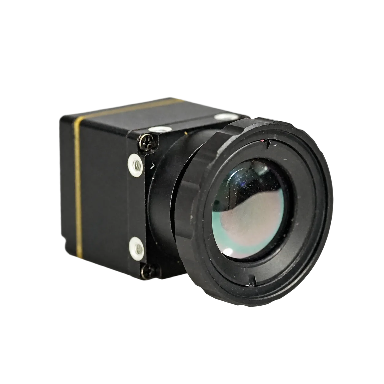
AeroMini 640: compare the lens options
A 640 × 512, 12 μm LWIR core with several factory lens choices. The published lens table lists 13 mm at 31.9° × 25.7° and 18 mm at 24.2° × 19.5°. Use the selected assembly’s FOV when planning coverage.
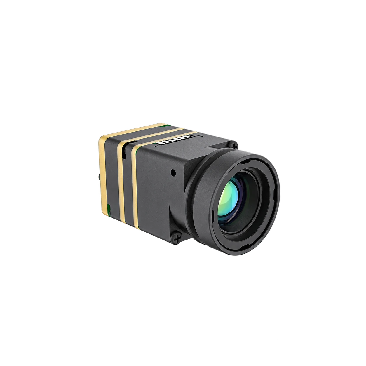
FlexMini 640: optics and host-side image analysis
A 640 × 512, 12 μm module with factory-fitted optics. Its product table lists 13 mm at 33.0° × 26.6° as an availability enquiry. The documented USB UVC Y16 workflow provides Y14 grayscale data for host-side processing, rather than calibrated temperature data.
SuperMini 640 / 640T: check the pixel pitch
A 640 × 512 detector with 8 μm pixels. Its active-array size differs from the 12 μm example in this article. Choose the listed optical assembly and distinguish the imaging-only 640 from the thermographic 640T.
AeroMini’s listed 13 mm view of 31.9° × 25.7° and FlexMini 640’s listed 13 mm view of 33.0° × 26.6° are a practical reminder to compare complete camera-and-lens configurations. They should not be forced into one formula by changing the underlying product values.
The 15 mm calculation in this article is a worked optics example. It is not a claim that these three products currently offer a standard 15 mm configuration. Refer to their product pages for listed lens choices, and discuss a different optical requirement before ordering.
For initial planning, use the CAMCUDA thermal imaging calculator. For a combined visible-and-thermal system, the UAV AI module selector compares the views of the listed configurations.
Five questions that make an FOV comparison useful
- Which detector area is used? Confirm resolution, pixel pitch and any active-region crop.
- Which angle is quoted? Request full horizontal, vertical and diagonal angles with a clear axis order.
- How was the number obtained? Distinguish a rectilinear calculation, linear estimate, optical-design value and measurement.
- Which delivered image does it describe? Specify lens revision, focus condition, correction, zoom and output mode.
- How will the sample be accepted? Agree the scene coverage or angular calibration method and the required tolerance before production.
For a basic distant-scene check, a centered target plane of known width at a known camera-to-plane distance can establish a horizontal angle through 2 × arctan[width ÷ (2 × distance)]. For calibration work, use a defined optical reference, alignment and test uncertainty.
Frequently asked questions
Why do 640 × 512, 12 μm, 15 mm FOV specifications differ?
The two quoted pairs can result from different calculations. The rectilinear arctangent model gives 28.72° × 23.15°; the linear approximation gives 29.34° × 23.47°. A supplier’s actual method still needs confirmation.
Which formula should I use for a theoretical FOV calculation?
Use FOV = 2 × arctan(sensor dimension ÷ (2f)) for an ideal rectilinear, distant-scene model. For a supplied camera, use its confirmed optical and output-mode specifications when planning coverage.
Does 29.34° × 23.47° prove the lens is defective?
No. Those numbers are consistent with a linear estimate, but they do not identify the lens quality or the supplier’s method. Confirm the optical specification and test conditions.
Can a shorter focal length alone explain both larger angles?
Not exactly in the stated distortion-free model. The horizontal angle implies about 14.6685 mm and the vertical angle about 14.7886 mm, so one focal length does not reproduce both values.
Do all 640 thermal cameras have the same field of view?
No. Pixel pitch, active pixel count, lens design and output crop all matter. A 640 × 512 detector with 8 μm pixels is smaller than one with 12 μm pixels.
Should I replace a published lens FOV with a calculator result?
No. Keep the published specification and the ideal calculation separate. Ask how the published value was established, then confirm the required field with the selected sample and output mode.
Sources and calculation notes
- Edmund Optics: Understanding Focal Length and Field of View — rectilinear angular-FOV relation and limits of first-order calculations.
- IRCameras: IFOV Calculator — pixel-size and focal-length calculation.
- Edmund Optics: Distortion — geometric mapping and lens-specific distortion.
- CAMCUDA AeroMini 64060 Hz imaging, FlexMini 64014-bit RAW · Y16 and SuperMini 640 / 640TUltra-light core product specifications, reviewed 25 October 2026.
All comparison-table values and the chart were independently calculated from the stated detector dimensions. Angles are converted from radians to degrees, and calculations retain full precision until display rounding. These calculated values are not lens acceptance measurements.
Choose the field your application needs.
Send the scene width, working distance, detector preference, host interface and quantity. We can help match a CAMCUDA module and lens configuration for sample evaluation.