Best IR Camera for OEM Integration: Engineering Guide to LWIR Cores & Sensor Selection
Best IR Camera for OEM Integration: Engineering Guide to LWIR Cores & Sensor Selection
Specifying the best IR camera for mission-critical OEM optronics, unmanned aerial systems (UAS), automated guided vehicles (AGVs), and long-range perimeter security means cutting through an enormous amount of marketing fluff. In the lab and out in the field, systems engineers and procurement leads constantly run into massive ambiguity on vendor datasheets—especially when vendors blur the line between active near-infrared (NIR) illuminator setups and true passive long-wave infrared (LWIR) microbolometer thermal cores. Here’s the deal: picking the wrong infrared tech class will tank your project. You risk total sensor blindness in zero-lux conditions without artificial lamps, severe dynamic blooming from active light bounce-back, massive signal drop through fog, marine aerosols, or battlefield smoke, and unacceptable pipeline lag in your edge AI computer vision stack.
For aerospace, defense, and industrial automation builds, your hardware choices must survive the harsh reality of the Size, Weight, Power, and Cost (SWaP-C) envelope. At the same time, you cannot afford to compromise on spatial resolution, thermal sensitivity (NETD ≤ 30 mK), dynamic range, or drift stability over wide thermal swings. Dropping an uncooled 640×512 vanadium oxide (VOx) focal plane array (FPA) with a tight 12 μm pixel pitch and precision athermalized Germanium glass into your platform gives you the spatial resolving power and target discrimination you need under Johnson’s Criteria. This guide breaks down the physical fundamentals of thermal radiation, ROIC readout dynamics, optical IFOV math, dual-spectrum edge tracking architectures, and battle-tested integration practices for embedded vision engineers.
Table of Contents
- 👉 1. Spectral Discrimination: Active NIR/SWIR vs. Passive LWIR Cores
- 👉 2. Microbolometer Architecture: VOx vs. a-Si & NETD Benchmarks
- 👉 3. Optical Engineering: IFOV, Germanium Lenses & Johnson’s Criteria
- 👉 4. Dual-Spectrum Fusion & On-Module Edge AI Tracking (6 TOPS)
- 👉 5. OEM Core Specifications & Hardware Comparison Matrix
- 👉 6. Electrical, Thermal & Mechanical Integration Guidelines
- 👉 7. Deep-Dive OEM Engineering FAQ
1. Spectral Discrimination: Active NIR/SWIR vs. Passive LWIR Cores
When you sit down to select an IR camera engine for an autonomous rig or a ruggedized pan-tilt surveillance head, the first step is sorting out the operational waveband, the underlying photon physics, and the atmospheric transmission windows. The infrared spectrum isn’t a monolith. It is carved up into distinct bands separated by atmospheric absorption bands caused by water vapor (H2O), carbon dioxide (CO2), and ozone (O3).
Look at how standard optoelectronic sensor classes compare across operational bands:
| Infrared Band | Wavelength (μm) | Operating Principle | Atmospheric Transmission & Constraints |
|---|---|---|---|
| Near-Infrared (NIR) | 0.75 – 1.0 μm | Active illumination reflection (Silicon CMOS) | Requires active LEDs (850/940 nm); severe Rayleigh scattering in fog/smoke; blooming from retroreflectors. |
| Short-Wave Infrared (SWIR) | 1.0 – 2.5 μm | Reflected photon detection (InGaAs focal planes) | Excellent penetration through atmospheric haze; relies on nightglow or active laser illumination; high sensor cost. |
| Mid-Wave Infrared (MWIR) | 3.0 – 5.0 μm | Direct thermal blackbody emission (InSb / MCT) | Requires cryogenic Stirling coolers (77 K); high sensitivity for long-range defense, but heavy SWaP-C and limited cooler lifespan. |
| Long-Wave Infrared (LWIR) | 8.0 – 14.0 μm | Direct thermal emission (VOx / a-Si Microbolometers) | Negligible atmospheric absorption in 8–14 μm window; zero-lux passive operation; immune to obscurants; ultra-low SWaP-C. |
Active NIR camera rigs are essentially conventional silicon CMOS sensors stripped of their IR-cut filters and paired with an array of 850 nm or 940 nm LEDs. They are cheap, but in demanding field conditions, they quickly fall apart. Because active light intensity drops off with the inverse-square law (1/R²), pushing detection range eats massive battery power. Even worse, active NIR creates an obvious beacon for any adversary equipped with basic night optics, while atmospheric particulate matter—like fog, dust, or industrial exhaust—causes severe Mie and Rayleigh scattering, throwing a wall of backscatter glare right into your lens.
Passive Long-Wave Infrared (LWIR) systems operating in the 8.0 μm to 14.0 μm window operate on completely different physics. Per Planck’s Radiation Law, any real-world object with a temperature above absolute zero emits electromagnetic radiation. For ambient terrestrial targets sitting between −40°C and +80°C (roughly 233 K to 353 K), the peak spectral radiant emittance sits squarely in the LWIR spectrum, governed by Wien’s Displacement Law:
λmax = b / T ≈ 2898 μm·K / 300 K ≈ 9.66 μm
Because that emission peak matches the 8–14 μm atmospheric transmission window, an LWIR core detects self-emitted thermal energy directly. You don’t need spotlighting, high-beam headlights cannot blind the sensor, and airborne particulates become largely transparent. For uncrewed systems, perimeter observation, and tactical robotics, uncooled LWIR cores deliver the ultimate mix of 24/7 target acquisition, stealth passive operation, and minimal SWaP-C drag. If you want to dive deeper into practical industrial installations, check out our guide on uncooled LWIR thermal modules for outdoor security and industrial monitoring.
2. Microbolometer Architecture: VOx vs. a-Si & NETD Benchmarks
Uncooled LWIR camera cores rely on a micro-machined MEMS focal plane array (FPA) known as a microbolometer. Unlike cryogenic photon detectors that convert incoming photons directly into electron-hole pairs across a narrow bandgap (demanding bulky, power-hungry cryocoolers to suppress thermal noise), microbolometers are purely thermal detectors. When incident LWIR radiation strikes an absorber membrane, its temperature climbs, shifting its internal electrical resistance. That resistance delta is measured and converted into digital counts by the underlying Readout Integrated Circuit (ROIC).
For a complete breakdown of fabrication processes and MEMS suspended bridge micro-structures, review the Wikipedia Microbolometer reference page.
Every single pixel in an uncooled FPA uses a microscopic absorbing plate suspended over the silicon ROIC substrate by tiny lithographic legs. These legs pull double duty: they form the electrical path for signal readout and provide high thermal isolation (ultra-low thermal conductance, G), keeping pixel heat from bleeding into neighboring detectors or the backplane substrate. The benchmark metric for detector material efficiency is the Temperature Coefficient of Resistance (TCR):
TCR = α = (1 / R) · (dR / dT)
In the optronics shop today, two core material technologies dominate the uncooled market:
- ⚙️ Vanadium Oxide (VOx): VOx is a mixed-valence transition metal oxide thin film that delivers high TCR numbers (−2.0% to −3.5% per Kelvin at room temp) alongside minimal 1/f flicker noise. VOx arrays achieve superior thermal sensitivity, driving core NETD ratings down to ≤ 30 mK. That sensitivity translates into crisp scene contrast and low noise floors, even when dealing with washed-out scenes like high-humidity maritime horizons or desert environments at thermal crossover.
- ⚙️ Amorphous Silicon (a-Si): Amorphous silicon can be deposited directly on conventional CMOS foundry lines, keeping tooling and wafer costs low. The tradeoff is performance: a-Si exhibits a lower TCR (−1.5% to −2.5%/K) and higher 1/f noise due to atomic disorder in the amorphous silicon lattice. That pushes a-Si core NETD ratings into the 40 mK to 60 mK bracket, producing noisier thermal imagery on low ΔT scenes.
Noise Equivalent Temperature Difference (NETD) Benchmark
NETD is the defining metric for thermal sensitivity. It represents the smallest temperature difference between a target and its background that generates a signal equal to the RMS noise floor of the camera system (an SNR of 1). The relationship is expressed as:
NETD = Vn / [ Rv · (ΔVs / ΔT) ] ∝ (4 · F#²) / [ π · Ad · τopt · (ΔL / ΔT) · D* ]
Where Vn is RMS noise, Rv is responsivity, F# is the optical focal ratio, Ad is active pixel surface area, τopt is optical transmittance, and D* is normalized detectivity. An industrial-grade VOx core with an NETD ≤ 30 mK (0.030°C) resolves micro-thermal signatures—like heat leaks through composite aircraft skins, residual thermal footprints on soil, or human skin contours behind thin outer garments. For more on international photonic standards, take a look at resources over at Novus Light Technologies.
3. Optical Engineering: IFOV, Germanium Lenses & Johnson’s Criteria
Infrared optical design is completely distinct from visible lens design. Standard optical glasses like BK7 or fused silica turn opaque in the 8–14 μm spectrum due to severe internal lattice absorption. Thermal lenses must instead be precision diamond-turned from high-index infrared crystal materials, primarily monocrystalline Germanium (Ge), Zinc Selenide (ZnSe), or specialized chalcogenide glass alloys, protected with high-durability anti-reflective (AR) and Diamond-Like Carbon (DLC) hard coatings.
To design an optical payload for standard Detection, Recognition, and Identification (DRI) envelopes, you have to calculate the Instantaneous Field of View (IFOV). IFOV defines the angle subtended by a single pixel element in object space:
IFOV (mrad) = [ Pixel Pitch d (μm) / Optical Focal Length f (mm) ]
Total horizontal (HFOV) and vertical (VFOV) angles are determined by the detector pixel count and optical focal length:
HFOV = 2 · arctan [ (Nh · d) / (2 · f) ] | VFOV = 2 · arctan [ (Nv · d) / (2 · f) ]
Johnson’s Criteria & Range Calculations
Under Johnson’s Criteria for thermal target resolution, range limits are determined by placing a critical threshold of line pairs (spatial cycles) across the target’s critical dimension (standardized at 0.75 m for a 1.8 m × 0.5 m human target, assuming a thermal contrast ΔT ≥ 2.0°C):
- ✅ Detection (1.5 cycles ≈ 3 active pixels across target): The operator or edge model spots an anomaly on screen.
- ✅ Recognition (6.0 cycles ≈ 12 active pixels across target): The system can categorize the target (e.g., human vs. animal vs. vehicle).
- ✅ Identification (12.0 cycles ≈ 24 active pixels across target): The system identifies specific target details (e.g., soldier carrying equipment vs. civilian; pickup truck vs. armored vehicle).
Operational distance (R) is calculated directly via:
R (meters) = Critical Dimension (meters) / [ Npixels · (IFOV in radians) ]
Here is how a 640×512 resolution VOx microbolometer core with a 12 μm pixel pitch performs across standard factory-fitted lens setups:
| Focal Length | Field of View (H×V) | IFOV | Human Detection (3 px) | Human Recognition (12 px) | Human Identification (24 px) |
|---|---|---|---|---|---|
| 4.9 mm | 76.2° × 64.2° | 2.45 mrad | 476 m | 119 m | 60 m |
| 9.1 mm | 45.8° × 37.3° | 1.31 mrad | 884.7 m | 221.2 m | 110.6 m |
| 13.0 mm | 33.0° × 26.6° | 0.92 mrad | 1,263.9 m | 316.0 m | 158.0 m |
| 19.0 mm | 22.9° × 18.4° | 0.63 mrad | 1,847.2 m | 461.8 m | 230.9 m |
| 35.0 mm | 12.5° × 10.0° | 0.34 mrad | 3,402.8 m | 850.7 m | 425.4 m |
For complete aerospace gimbal payloads, check out our pre-configured 640×512 UAV thermal imaging cameras built specifically for high-vibration airborne turrets.
4. Dual-Spectrum Fusion & On-Module Edge AI Tracking (6 TOPS)
Modern unmanned payloads increasingly rely on dual-spectrum payloads that integrate a high-frame-rate visible Electro-Optical (EO) camera and an uncooled LWIR core, managed in real time by an onboard hardware Neural Processing Unit (NPU). In full daylight, the visible sensor gives you crisp spatial edge resolution and true-color context. When darkness falls, or when dust and thermal camo hide the target, the LWIR thermal feed pulls out heat signatures instantly.
Managing these video feeds simultaneously on an embedded computing board requires a dual-channel MIPI-CSI pipeline hooked into a heterogeneous multi-core SoC (Arm Cortex-A76 plus Cortex-A55 cores) coupled with a dedicated 6 TOPS (Tera-Operations Per Second) NPU accelerator. In the shop, here are the real-time processing tasks the hardware executes simultaneously:
- ⚙️ Multi-Spectral Spatial Alignment & Fusion: Real-time affine perspective correction warps the thermal image array onto the visible stream pixel-for-pixel, driving Picture-in-Picture (PIP) or alpha-blended false-color overlays.
- ⚙️ Real-Time Non-Uniformity Correction (NUC): High-speed background filtering cleans out spatial FPA gain and offset drift, stripping fixed-pattern noise without dropping frames.
- ⚙️ Low-Latency Deep-Learning Tracking: Quantized neural models (YOLO-based or MobileNet backbones) run straight on the uncompressed raw pixel pipeline. The 6 TOPS NPU executes bounding-box prediction, centroid calculation, and Kalman trajectory filters at latencies as low as 8 ms.
- ⚙️ Multi-Target Tracking Engine: Manages up to 120 target tracks simultaneously at relative target closure speeds up to 450 km/h, supporting reticle locking, close-to-lock, route pre-mapping, and lost-target re-acquisition modes.
- ⚙️ Direct Autopilot Protocol Integration: Tracking offsets, target coordinates, and gimbal rate commands stream out over native Crossfire (CRSF) or MAVLink serial buses, providing direct closed-loop navigation for BetaFlight and ArduPilot autopilots.
5. OEM Core Specifications & Hardware Comparison Matrix
To help you evaluate architecture options during engineering trade studies, here is a direct comparison between an ultra-low SWaP standalone microbolometer core and an integrated dual-spectrum AI tracking platform.
| Engineering Parameter | MD-64CA Standalone LWIR Core | TM02-SOLO T Dual-Spectrum AI Module |
|---|---|---|
| Detector Architecture | Uncooled VOx Focal Plane Array | Dual: Uncooled VOx Thermal + 1/1.8″ EO CMOS |
| Thermal Array Resolution | 640 × 512 pixels | 640 × 512 pixels |
| Visible Video Resolution | N/A (Thermal Only) | 1920 × 1080 @ 120 Hz (0.001 lux min illum.) |
| Pixel Pitch & Spectral Band | 12 μm | 8.0 – 14.0 μm (LWIR) | 12 μm | 8.0 – 14.0 μm (LWIR) |
| Thermal Frame Rate & NETD | 50 Hz | ≤ 30 mK (≤ 0.03°C) | 50 Hz | High-sensitivity VOx FPA |
| Onboard Compute Engine | Integrated FPGA Image Engine / NUC | 6 TOPS NPU + Arm Cortex-A76 (2.4 GHz) / A55 (1.8 GHz) |
| Target Tracking Latency | < 20 ms internal video path delay | 8 ms processing latency reference; up to 120 tracks |
| Video & Control Interfaces | CVBS (Analog), USB UVC, or MIPI-CSI | MIPI internal, CRSF protocol (BetaFlight / ArduPilot) |
| Power Input & Consumption | 5 – 24 V DC wide-input | < 0.7 W power draw | Regulated 9 – 16 V DC |
| Dimensions & Total Mass | 23.1 g base module weight | Board: 45 × 45 × 26 mm (42.5 × 42.5 mm mount) |
Product Showcase: MD-64CA 640×512 Uncooled VOx Thermal Imaging Camera Module
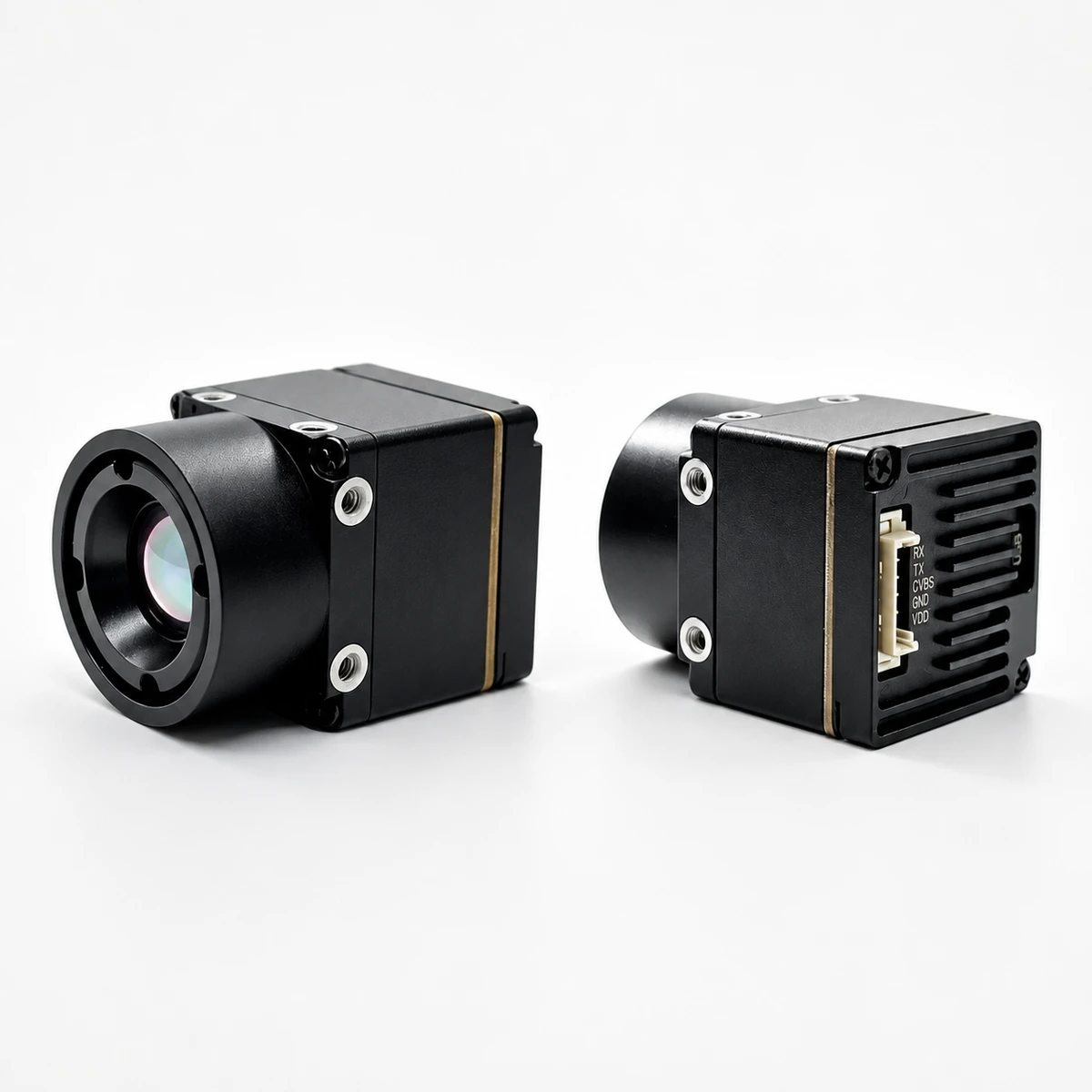
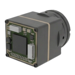
MD-64CA Compact OEM Thermal Core
The MD-64CA is built for OEM vision integrators who need full 640-grade LWIR imaging in a form factor under 25 grams. Powered by a 640×512 VOx microbolometer with a 12 μm pixel pitch and an NETD rating ≤ 30 mK at F1.0, this core outputs crisp, high-contrast thermal video at 50 Hz. Consuming less than 0.7 W of power while accepting an ultra-flexible 5–24 V DC wide-input rail, the MD-64CA mounts effortlessly into handheld scopes, industrial automation heads, security PTZ housings, and compact aerial gimbals.
You can configure the MD-64CA with factory-installed, athermalized Germanium optics. Here is how the optical options and pricing benchmarks line up:
- ✅ 9.1 mm Lens ($475.00 Standard Stock): 45.8° × 37.3° FOV | 1.31 mrad IFOV | 884.7 m Detection range.
- ✅ 4.9 mm Lens ($522.50 / +10%): 76.2° × 64.2° FOV | 2.45 mrad IFOV | 476 m Detection range.
- ✅ 4.1 mm Lens ($522.50 / +10%): Ultra-wide field of view for close-in situational awareness and driver vision systems.
- ✅ 13.0 mm Lens ($522.50 RFQ Option): 33.0° × 26.6° FOV | 0.92 mrad IFOV | 1,263.9 m Detection range.
- ✅ 19.0 mm Lens ($522.50 RFQ Option): 22.9° × 18.4° FOV | 0.63 mrad IFOV | 1,847.2 m Detection range.
- ✅ 35.0 mm Lens ($522.50 RFQ Option): 12.5° × 10.0° FOV | 0.34 mrad IFOV | 3,402.8 m Detection range.
Interface support spans standard USB UVC (USB-VDD, D−, D+, GND), analog CVBS (Rx, Tx, CVBS, GND, VCC), and raw digital MIPI-CSI output, backed by an automated shuttered NUC with internal pipeline delays below 20 ms.
Product Showcase: 6 TOPS Dual-Spectrum UAV AI Tracking Module with 640×512 Thermal Camera
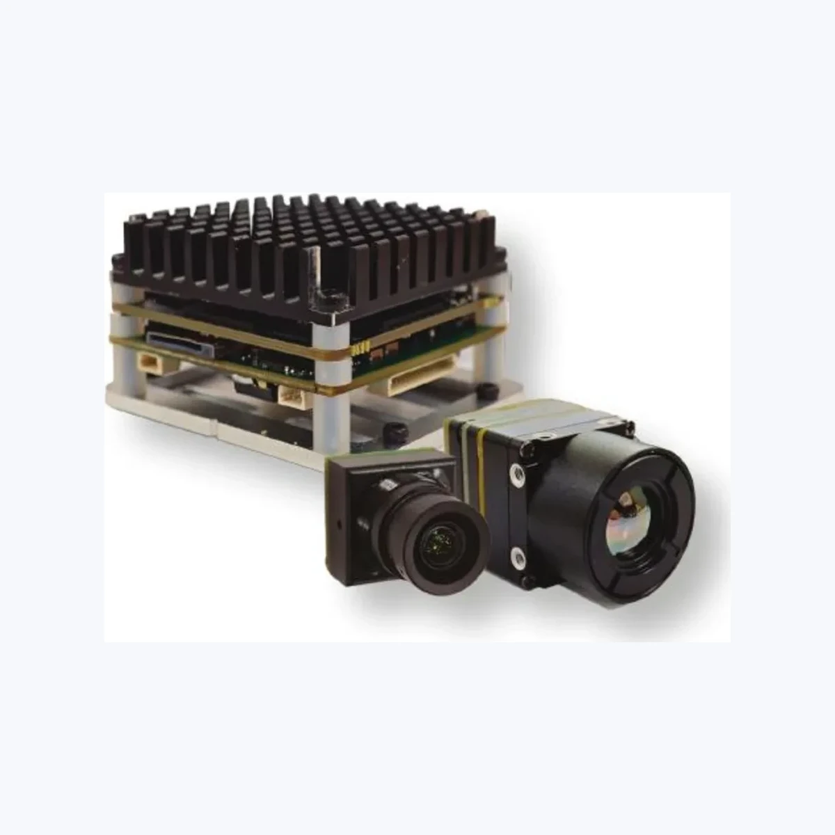
TM02-SOLO T Dual-Spectrum AI Tracking Engine
The TM02-SOLO T is a fully integrated optronics and edge-compute payload engineered for UAV manufacturers and unmanned vehicle designers. It mates a 640×512 50 Hz uncooled VOx thermal sensor with a 1080p @ 120 Hz starlight (0.001 lux) visible imager onto a tiny 45×45×26 mm carrier board. The computing stack is driven by an Arm Cortex-A76 (2.4 GHz) / Cortex-A55 (1.8 GHz) multi-core processor alongside a dedicated 6 TOPS edge AI acceleration core.
Built to track personnel and vehicles across shifting lighting and thermal signatures, this module processes all deep learning models on-module, avoiding video compression lag and ditching reliance on fragile ground station downlinks. It tracks up to 120 discrete targets simultaneously with an internal pipeline latency of just 8 ms, maintaining lock at dynamic closing speeds up to 450 km/h.
| Subsystem | Parameter | Specification Value |
|---|---|---|
| AI & Tracking | Target Types & Range | Person (170 m reference), Vehicle (400 m reference) |
| Tracking Modes | Reticle locking, close-to-lock, route pre-map, lost-target recall, PIP | |
| Min Target & Speed | 10×10 pixels minimum | Up to 450 km/h dynamic speed | |
| Visible Sensor (EO) | Optical Sensor / Lens | 1/1.8-inch CMOS | 8.45 mm focal length | 0.001 lux reference |
| Resolution / FOV | 1920×1080 @ 120 Hz | D 66.3° / H 57.1° / V 30.4° | |
| Thermal Sensor (LWIR) | FPA Detector / Lens | Uncooled VOx (8–14 μm, 12 μm pitch) | 9.1 mm focal length |
| Resolution / FOV | 640×512 @ 50 Hz | D 61.8° / H 47.7° / V 38.2° | |
| Compute / Flight Control | Protocol & Flight Control | CRSF protocol | Native support for BetaFlight and ArduPilot |
Integration Note: The LWIR sensor on the TM02-SOLO T is tuned specifically for target extraction and dual-spectrum edge tracking. It does not output calibrated radiometric temperature arrays out of the box without dedicated custom calibration profiles.
6. Electrical, Thermal & Mechanical Integration Guidelines
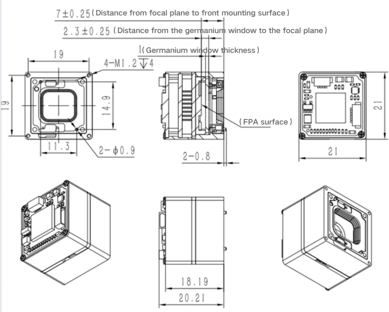
Integrating uncooled microbolometer cores and dual-spectrum AI platforms into real-world airborne, vehicular, or maritime chassis requires rigorous mechanical, thermal, and electrical practices. If you cut corners on hardware design, sensor noise and thermal drift will destroy your imagery.
1. Power Supply Conditioning & Inrush Current Management
Microbolometer ROIC bias networks hate power supply noise. Switching noise on your DC rails instantly shows up as crawling horizontal bars, fixed-pattern noise, or degraded NETD floors. You need dedicated ultra-low-noise LDO regulators or high-frequency synchronous buck regulators with output ripple clamped below 30 mV peak-to-peak.
Keep in mind that when a microbolometer core fires up and its NPU initializes, startup inrush current can jump to 2.5 times nominal operating draw for 50 to 150 ms. Make sure your power distribution network integrates soft-start circuits and low-ESR ceramic bypass capacitor banks right next to the module’s input pins to eliminate brownout resets on your host flight controller.
2. Thermal Dissipation & Isothermal Mechanical Baseplates
Because microbolometers measure microscopic temperature changes down to millikelvins, the FPA is highly vulnerable to thermal gradients moving across its aluminum housing. Asymmetrical heat shedding from nearby electronics—like ESCs, VTX transmitters, or multi-core SoCs—will create uneven thermal gradients across the core. This introduces image shading artifacts that quickly overpower the internal Non-Uniformity Correction (NUC) algorithms.
To keep the thermal core rock-solid across standard operating ranges (−20°C to +60°C):
- ⚙️ Bolt the thermal camera core to a CNC-machined 6061-T6 aluminum mounting plate that acts as an isothermal heat sink.
- ⚙️ Install high-conductivity gap pads or phase-change TIM (thermal conductivity k ≥ 3.0 W/m·K) between the camera housing and your outer enclosure.
- ⚙️ Isolate hot computing engines (like the 6 TOPS edge board) with dedicated heat paths routed directly to external heat sinks, keeping conducted heat away from the Germanium lens barrel.
3. Non-Uniformity Correction (NUC) and Shutterless Operation
All microbolometer FPAs experience baseline drift as ambient temperatures fluctuate. Periodic Non-Uniformity Correction is necessary to refresh pixel gain and offset tables. The MD-64CA module features an integrated solenoid shutter that automatically drops across the sensor for a fraction of a second to run a single-point flat-field calibration whenever internal thermistors detect a pre-set thermal delta.
In high-vibration drone tracking or continuous weapon-sight applications where a 200 ms mechanical shutter freeze is unacceptable, you can configure the firmware for shutterless algorithmic NUC. This mode processes continuous scene statistics to refresh offset coefficients dynamically without physical shutter movement.
4. Regulatory Compliance & Supply Chain Documentation
If you are packaging optronics for aerospace, defense, or critical infrastructure programs, export compliance and statutory documentation are non-negotiable. For gear operating in North American, European, and allied defense sectors, tracking the supply chain origin of your microbolometer cores ensures hassle-free procurement. For complete guidance on paperwork requirements, review our technical guide on NDAA thermal camera module documentation and RFQ requirements.
7. Deep-Dive OEM Engineering FAQ
What is the primary physical difference between an active NIR night vision camera and a true LWIR thermal IR camera?
True Long-Wave Infrared (LWIR) cores operate in the 8.0 to 14.0 μm spectrum using microbolometer focal plane arrays (typically Vanadium Oxide, VOx). They detect self-emitted blackbody thermal radiation given off by all physical objects above absolute zero. LWIR imagers require zero artificial illumination, operate with complete passive stealth in pitch darkness (0 lux), punch straight through atmospheric obscurants whose particulate diameters are smaller than thermal wavelengths, and produce scene contrast based entirely on thermodynamic surface temperature deltas rather than reflected visible light.
Why do budget 256×192 thermal cores fail at long-range detection compared to 640×512 12 μm VOx cores?
When you attempt to detect a human target (1.8 m × 0.5 m) at 1,000 meters using matching optical fields of view, a 256×192 sensor projects less than one whole pixel across the target width. The target’s thermal signature is averaged into the background noise floor, making detection mathematically impossible and causing edge AI models to fail. A 640×512 core with a 12 μm pixel pitch and a telephoto lens (such as 19 mm or 35 mm) delivers a much tighter IFOV (0.63 to 0.34 mrad). This puts the required 6 to 12 active pixels across the target profile, enabling reliable classification and tracking of personnel, vehicles, and vessels at distance without false alarms.
Can a dual-spectrum AI tracking module be utilized directly for industrial radiometric temperature inspection?
To deliver that contrast, the onboard Image Signal Processor (ISP) runs non-linear enhancement routines, including scene-adaptive Automatic Gain Control (AGC), Digital Detail Enhancement (DDE), and local histogram equalization. These dynamic algorithms manipulate the raw digital pixel values, breaking the linear relationship between digital pixel intensity and absolute surface temperature. Certified radiometric cameras, by contrast, maintain an unmanipulated linear temperature lookup table (LUT) calibrated against calibrated blackbody references, while continuously compensating for lens housing thermistors, ambient air temperature, path distance, and target emissivity to output accurate surface readings (±2°C or ±2%).
What are the critical electrical and communication considerations when pairing a dual-spectrum module with BetaFlight or ArduPilot flight controllers?
For software telemetry, tracking vectors and camera commands travel over a standard UART serial line running Crossfire (CRSF) or MAVLink protocol. In ArduPilot, you configure the corresponding serial port baud rate (e.g., 115200 or 416666 baud for CRSF) and assign the module telemetry outputs to direct gimbal rate corrections or autonomous vehicle yaw tracking subroutines. You also need to confirm that your transmitter switch mapping matches the module’s mode channels so pilots can cycle between visible, thermal, PIP, and autonomous tracking modes without lag during flight.
📚 References & Further Reading
- Industry Standard: Wikipedia – Microbolometer Physics & Architecture
- Industry Standard: Novus Light Technologies – Photonics and Infrared Industry News
- Related Guide: Uncooled LWIR Thermal Modules for Outdoor Security and Industrial Monitoring
- Related Guide: NDAA Thermal Camera Module North America RFQ Documents & Compliance
- Product Overview: 640×512 UAV Thermal Imaging Camera Systems