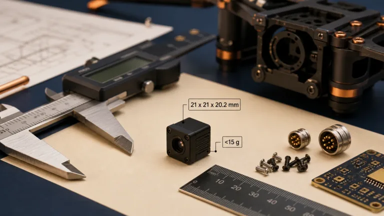
Thermal Imager Selection Guide: OEM Core Integration vs Handheld Devices
Thermal Imager Selection Guide: OEM Core Integration vs Handheld Devices
Selecting an industrial thermal imager requires a no-nonsense evaluation of electro-optical physics, digital signal architectures, and mechanical constraints. Industrial inspection, UAV payloads, machine vision, and field observation place different demands on spatial resolution, thermal sensitivity, temperature measurement, and SWaP-C (Size, Weight, Power, and Cost). Engineering teams face a fundamental architectural choice: embed a modular OEM thermal core into a custom host, or deploy a standalone handheld instrument with its own display, controls, and power supply. Neither approach is universally better; the task, integration budget, and acceptance evidence should decide.
This engineering selection guide examines uncooled Long-Wave Infrared (LWIR) Vanadium Oxide (VOx) microbolometers, detector sampling, digital video and control interfaces, optical Modulation Transfer Function (MTF), and detection, recognition, and identification (DRI) validation. It retains the distinction between a native 1280×1024 requirement and a 640×512 design choice. The current AeroMini 640 is used only as a documented OEM integration example; it is neither a native 1280×1024 replacement nor a self-contained handheld camera. The handheld comparison is a requirements checklist rather than a product recommendation.
Technical author: Daniel · Hardware Support. Sales contributors: Vivian, Lena, and Sophie.
Table of Contents
- 👉 1. Core Physics & Sensor Architecture: Uncooled VOx LWIR Technology
- 👉 2. OEM Thermal Cores vs Handheld Instruments: Architectural & SWaP-C Tradeoffs
- 👉 3. Digital Video Interfaces, Control Protocols, and Host Bus Architectures
- 👉 4. Optical Selection, Lens Matching, and DRI Modeling
- 👉 5. Current OEM Example & Handheld Requirements Comparison
- 👉 6. OEM Sourcing, Compliance, and RFQ Engineering Checklist
- 👉 7. Frequently Asked Questions (FAQ)
1. Core Physics & Sensor Architecture: Uncooled VOx LWIR Technology
Many industrial thermal cameras operate in the 8 µm to 14 µm LWIR band, which includes an atmospheric transmission window and useful emission from everyday objects. Planck’s law describes the spectrum; Wien’s displacement law gives the wavelength of peak spectral radiance. For blackbodies from −40°C to +150°C, the peak shifts from approximately 12.43 µm to 6.85 µm, so it does not remain entirely within 8–14 µm. The Stefan–Boltzmann law instead describes total blackbody emission. Passive thermal imaging can work in darkness, but water vapor, rain, fog, smoke, dust, foliage, and other obstructions can attenuate or block the signal; performance depends on the actual optical path.
Uncooled thermal sensors commonly use a microbolometer Focal Plane Array (FPA) operating near its local ambient temperature. In a typical pixel, an infrared-absorbing membrane is thermally isolated above a silicon Readout Integrated Circuit (ROIC); vacuum packaging helps limit heat loss through gas. Cooled photon detectors use different detection mechanisms and cooling arrangements, with operating temperatures that depend on detector material and design. They do not all require a Stirling cooler at 77 K. Packaging, biasing, thermal stability, and readout electronics matter as much as the detector label.

When the pixel absorber receives infrared radiation, absorbed power causes a small temperature change (ΔT), which changes the thermistor resistance. Around a specified operating point, the Temperature Coefficient of Resistance (TCR), α = (1/R)(dR/dT), gives the first-order relation:
ΔR ≈ R0 · α · ΔT
Here, R0 is the resistance at the operating point, α is its local TCR, and ΔT is the pixel temperature change, not directly the scene temperature. This linear approximation is valid for sufficiently small changes. The ROIC biases and samples the pixel response, and analog-to-digital conversion produces values for subsequent correction and image processing. Bias self-heating, readout noise, substrate drift, and optical transmission affect the final signal.
Vanadium Oxide (VOx) vs. Amorphous Silicon (a-Si)
Vanadium Oxide (VOx) and Amorphous Silicon (a-Si) are both used in uncooled microbolometers. The material name alone does not establish sensitivity, response speed, or long-term stability. Compare the completed detector and camera under matched conditions:
- ⚙️ Temperature Coefficient of Resistance (TCR): TCR depends on film composition, processing, and operating temperature. A larger magnitude can improve electrical responsivity, but resistance, bias limits, and noise also affect signal-to-noise ratio. Do not infer a universal VOx-over-a-Si ranking from nominal TCR ranges.
- ⚙️ 1/f Flicker Noise Characteristics: Low-frequency noise depends on the material process, geometry, bias, and readout design. Request measured noise and drift behavior for the offered detector. Non-Uniformity Correction (NUC) and Flat-Field Correction (FFC) frequency also depend on temperature change and firmware; the material does not guarantee uninterrupted imagery.
- ⚙️ Thermal Time Constant (τ): The first-order thermal model is τ = Cth / Gth, where Cth is pixel heat capacity and Gth is thermal conductance. Reducing conductance can improve thermal response amplitude while increasing settling time. Ask for the actual time constant and measure moving-scene response separately from frame rate, exposure, processing delay, and display latency.
Pixel Pitch Scaling: The 12 µm Architecture
Moving from 25 µm or 17 µm pixels to 12 µm pixel pitch can reduce the active sensor width for a fixed array size. It changes lens design and packaging tradeoffs, but it does not automatically improve every system metric:
- ⚙️ Opto-Mechanical Mass: At the same angular pixel sampling (IFOV), a smaller pixel permits a proportionally shorter focal length. At a fixed f-number this can reduce aperture diameter, but actual lens mass also depends on material, element count, mounting, and environmental requirements; a universal 50% saving is not justified.
- ⚙️ SWaP-C Budget: Smaller active areas can support compact packages. Evaluate the complete assembly, including lens, flange, interface board, cable, heat path, enclosure, and host power conversion. Bare-core dimensions or weight alone do not define a UAV payload or handheld instrument budget.
- ⚙️ Array Scaling: A 1280×1024 array contains four times as many pixels as a 640×512 array. At the same pitch it has twice the active width and height, which changes image-circle requirements and field of view. Manufacturing yield, delivered cost, and mechanical interchangeability require evidence; pixel pitch alone does not guarantee them.
Noise Equivalent Temperature Difference (NETD) Physics
Noise Equivalent Temperature Difference (NETD) is the scene temperature difference giving a signal equal to the measured noise under stated test conditions. It is useful for comparing thermal sensitivity, but it is neither temperature accuracy nor a guaranteed detection threshold in a field scene. A basic noise-to-response definition is:
NETD = Vn / | dVs / dTBB |
Here, Vn is RMS output noise and |dVs/dTBB| is the magnitude of the local output response to blackbody temperature, using compatible units and the same measurement conditions. Compare NETD only with scene and camera temperature, lens f-number and transmission, frame rate, integration settings, bandwidth, and processing documented. Values in millikelvins describe sensitivity; they do not imply millikelvin absolute temperature accuracy:
- ⚙️ Comparing 50 mK and 35 mK: Under matched conditions, a lower NETD can help reveal smaller thermal differences. Whether either value is sufficient depends on feature size, contrast, optics, motion, and the inspection acceptance test; neither is a universal industrial threshold.
- ⚙️ Current OEM Example: The AeroMini 640 product documentation states NETD ≤30 mK at 25°C with F/1.0 optics. Request the test method and configuration when comparing another camera. Temperature measurement is a separate radiometric-version capability, not a consequence of this NETD value.
- ⚙️ Comparing 20 mK Claims: A documented 20 mK value may indicate lower noise than 30 or 50 mK under equivalent tests. It does not mean microkelvin detail, immunity to fog or rain, or guaranteed long-range detection. Validate low-contrast scenes through the intended optics and environment.
2. OEM Thermal Cores vs Handheld Instruments: Architectural & SWaP-C Tradeoffs
When selecting a thermal imager, engineering leads need to decide whether a modular OEM sensor core or a standalone handheld observation instrument matches their operational environment, software stack, and mechanical budget.
1. OEM Thermal Imaging Cores
Modular OEM thermal imaging cores, available through the thermal imaging cores catalog, combine a detector, readout electronics, and some level of signal processing for integration into a larger host. They may be used in UAV gimbals, factory enclosures, mobile robots, or custom optical systems. The processing architecture, supplied boards, and boundary between camera firmware and host software vary by product.
An OEM design can omit a built-in display, handheld housing, buttons, and battery, allowing the system integrator to allocate size, weight, and power to the application. AeroMini provides one current compact 640×512 example. However, access to raw pixels, NUC calibration tables, bad-pixel correction, color maps, or custom algorithms is not automatically open. Specify which controls and data formats the application needs, and confirm them for the ordered hardware and firmware before committing to a host architecture.
OEM integration requires a defined power supply, thermal path, mechanical mounting, video capture pipeline, and control software. Some kits provide useful boards and examples; others require custom carriers or drivers. Request board-specific pinouts and electrical limits, complete-assembly CAD, timing and pixel-format documentation, and the supported SDK package. Budget for startup, reconnect, FFC interruption, thermal drift, and end-to-end latency tests rather than treating a connector match as proof of compatibility.
2. Handheld Thermal Observation Instruments
Standalone handheld thermal instruments generally combine a thermal sensor and optics with a display, user controls, and a portable power source. The exact display, battery, enclosure, accessories, and weather protection are product-specific. Verify a documented ingress-protection rating and its test conditions if the use case requires it; handheld form alone does not imply IP66, IP67, or any other rating.
Handheld instruments are useful when field personnel need to observe a scene without designing a host PCB or video pipeline. Inspectors, rescue teams, maintenance staff, and wildlife researchers should still validate the device for their own workflow. Palettes, digital zoom, recording, connectivity, and display readability vary. A thermal observation viewer need not provide calibrated temperature measurement; quantitative inspection requires appropriate radiometric capability, accuracy specifications, and a suitable measurement method.
The tradeoff is reduced freedom to choose the enclosure, interface, firmware, and mounting geometry. Compare complete operating weight including the battery, runtime at the required conditions, glove operation, focus control, storage and export options, and any available video or raw-data access. Neither a universal 550 g weight class nor a universal data-output limitation follows from being handheld. A compact OEM module remains a component even if its product photo shows it held in a hand.
3. Digital Video Interfaces, Control Protocols, and Host Bus Architectures
For an OEM integration, define an acceptable end-to-end delay and a stable capture path between the camera and host. Sensor response, readout, transport, buffering, processing, and display each contribute. The infrared camera module OEM buying guide provides additional sourcing context; the exact board and firmware documentation must establish electrical and data compatibility.
Digital Video Output Pipelines
The following are interface families an integrator may encounter, not a list of outputs supplied by every core or by AeroMini. A standard name does not establish resolution, pixel format, calibration, simultaneous-output capability, or host support:
- ⚙️ BT.1120 Parallel Video: ITU-R BT.1120 defines digital interfaces for 1920×1080 studio signals. A device using this label still needs documented timing, clocking, synchronization, word width, and pixel packing. The label alone does not prove a native 1280×1024 stream, 50 Hz output, raw data, or zero pipeline latency.
- ⚙️ BT.656 Video: ITU-R BT.656 describes 525-line and 625-line digital component video based on BT.601 4:2:2 coding, including embedded timing references. A thermal-camera implementation may have model-specific pixel packing or conversion. Confirm active image dimensions, clock rate, byte order, synchronization, and any resampling with the host capture driver.
- ⚙️ SDI (Serial Digital Interface): SDI implementations carry specified video formats over a serial link, commonly coaxial cable. Transmitters, receivers, processing, and buffering introduce nonzero delay. Supported cable reach depends on rate, cable loss, connectors, equalization, and equipment. Measure the complete path at the required format instead of assuming zero latency or a universal 100 m reach.
- ⚙️ Camera Link: Camera Link is a machine-vision camera interface whose configuration and pixel mapping must match the frame grabber. A camera may transmit device-defined pixel values through it, but the interface does not make them raw 14-bit data, calibrated radiometry, or kelvin values. Request bit depth, packing, metadata, calibration, trigger behavior, and acquisition examples.
- ⚙️ MIPI CSI-2 via Hardware Bridge: CSI-2 can use the MIPI D-PHY physical layer. A bridge must match the camera timing and data format to the host’s lane count, rate, CSI-2 data type, and supported driver path. A compatible connector or physical layer does not guarantee support on Jetson, NXP, Rockchip, or an ISP; validate the exact host, software version, and output mode.
Serial Command & Control Pipelines
Control commands and video transport are separate parts of the design. First establish the electrical interface, then the protocol and supported firmware commands:
- ⚙️ RS-232: RS-232 uses its own single-ended electrical signaling levels; it is not interchangeable with a bare TTL/CMOS UART. Confirm signal voltage limits, polarity, ground reference, transceiver requirements, connector orientation, and cable length. A pin labeled RS232 must not be assumed safe to connect directly to a microcontroller UART.
- ⚙️ RS-422 / RS-485: These are differential electrical-interface families with different driver and network arrangements. Confirm which one the selected board implements, its termination, biasing, topology, common-mode limits, and isolation needs. Differential signaling can improve noise robustness, but reliable slip-ring or industrial-cable operation still requires validation.
- ⚙️ Command Set Capabilities: Use the manual matching the camera firmware for baud rate, framing, checksums, responses, and supported functions. NUC/FFC, palettes, zoom, image processing, and telemetry are available only if documented for that configuration. Test acknowledgements, timeouts, reconnects, and failure recovery; a serial bus name does not promise any particular command.
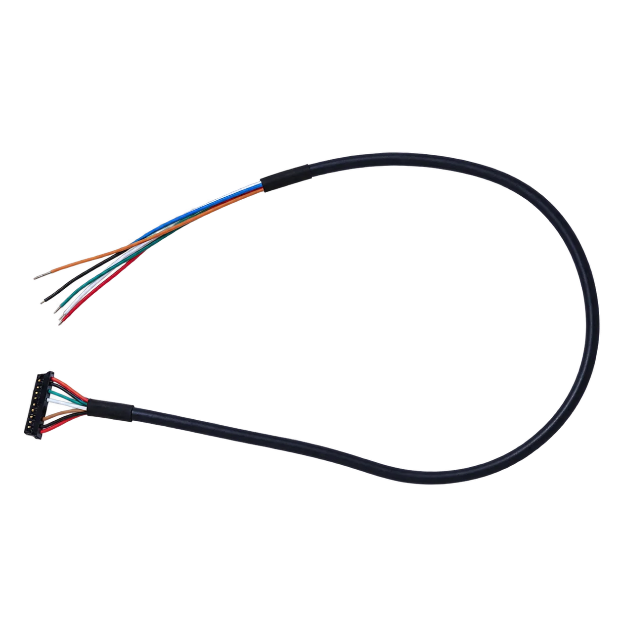
The AeroMini USB + CVBS + MIPI and Type-C + CVBS tailboards are different configurations. The published 16-pin USB/CVBS and 26-pin MIPI/DVP drawings apply to their corresponding board connections, not automatically to Type-C. POWER_IN1 on the 16-pin reference and POWER_IN2 on the 26-pin reference are 5 V inputs; never connect either to 12 V. Verify the approved input and serial electrical levels for the actual board. Request the matched datasheet and connector documentation and Linux drivers, examples, and SDK resources for the intended camera, host, and output mode; availability of a resource package does not promise every host or an open-source driver.
4. Optical Selection, Lens Matching, and DRI Modeling
Ordinary visible-light optical glasses such as BK7 and fused silica are unsuitable for typical 8–14 µm imaging paths. LWIR lenses use materials such as Germanium (Ge) or suitable Chalcogenide formulations, with coatings matched to the spectral band and environment. Anti-reflection treatments, exterior durability, thermal focus shift, lens transmission, and mounting stress belong in the optical specification. A material or coating name alone does not establish environmental performance.
Optical Throughput & F-Number Impact
For a comparable extended scene, similar transmission, and matched imaging conditions, irradiance at the detector approximately scales with the inverse square of f-number. This simplified relation helps compare optical throughput:
Detector Irradiance ∝ 1 / (F#)2
Under those assumptions, the throughput ratio for F/1.0 versus F/1.4 is (1.4/1.0)2 = 1.96, approximately twice. Actual signal and NETD also depend on transmission, vignetting, detector behavior, exposure, and processing. A faster lens can help sensitivity, but its measured MTF, focus across temperature, image circle, and mechanical fit must also meet the application requirements.
Spatial Resolution and Field of View Equations
Focal length and detector geometry set first-order angular sampling and coverage. These geometric formulas should be checked against the actual lens field-of-view data and distortion. Pixel sampling is not equivalent to resolved detail because optics, motion, noise, and processing also matter:
1. Instantaneous Field of View (IFOV): The angular field covered by a single detector pixel, measured in milliradians (mrad):
IFOV (mrad) ≈ [ Pixel Pitch (µm) / Focal Length (mm) ]
Generic example: A 12 µm pixel pitch with a 50 mm lens gives IFOV = 12 / 50 = 0.24 mrad. Using the small-angle approximation, the projected sampling footprint at 1,000 m is about 0.24 m per pixel in each axis for square pixels and a perpendicular scene plane. This is a geometric sample size, not a measured target-recognition distance or a guarantee that a one-pixel feature is resolved.
2. Horizontal Field of View (HFOV): The total horizontal angular spread of the scene:
HFOV = 2 · arctan [ (Nh · Pixel Pitch) / (2 · Focal Length) ]
Here, Nh is the horizontal pixel count, and pixel pitch and focal length must use the same length unit inside the arctangent. Native 1280×1024 and 640×512 arrays have different active widths at the same pitch. At the same focal length their per-pixel IFOV is equal, while the larger array covers a wider field. At the same field of view, the larger array can provide denser angular sampling if the optics support it. At equal frame rate and bits per pixel, it also produces four times the pixel payload before transport overhead.
Johnson’s Criteria: DRI Modeling for 12 µm Microbolometer Systems
Johnson-style criteria relate target tasks to spatial information under defined observer and test assumptions. Published thresholds vary with target set, contrast, image quality, and probability convention, so a fixed pixel count is not a universal guarantee. Define the task and required probability first, then validate a model against representative scenes:
- ⚙️ Detection: Specify what counts as finding an object against its background, the minimum object dimension and contrast, false-alarm tolerance, and required probability. Sampling is one input alongside atmospheric transmission, optics, sensor noise, motion, and image processing.
- ⚙️ Recognition: Specify the categories the operator or algorithm must distinguish and the scene conditions. A nominal number of line pairs or pixels cannot establish performance without the corresponding target definition, observer method, and probability criterion.
- ⚙️ Identification: Specify the features that must be resolved, the required confidence, and a repeatable acceptance test. Account for lens MTF, sampling, focus, display or algorithm behavior, and environmental variation; do not convert a geometric footprint directly into an identification-range promise.
A shorter focal length generally increases field coverage; a longer focal length narrows it and reduces angular pixel size for a fixed detector pitch. Select optics from the documented choices for the actual camera version, and validate focus, motion tolerance, thermal stability, and image-circle coverage. Digital zoom does not add native detector samples. If the requirement is native 1280×1024, obtain an appropriate 1280-class product and its interface evidence; the AeroMini 640 example below cannot satisfy that resolution by interpolation.
5. Current OEM Example & Handheld Requirements Comparison
The two procurement paths below serve different needs. AeroMini 640 is a current documented OEM example for evaluating a native 640×512 core. The standalone handheld checklist identifies evidence to obtain from a supplier; it does not recommend a particular handheld SKU or assign specifications to the illustrative image. A native 1280×1024 requirement needs a suitable 1280-class product, not the 640 example.
CAMCUDA AeroMini 640×512 OEM Thermal Camera Core
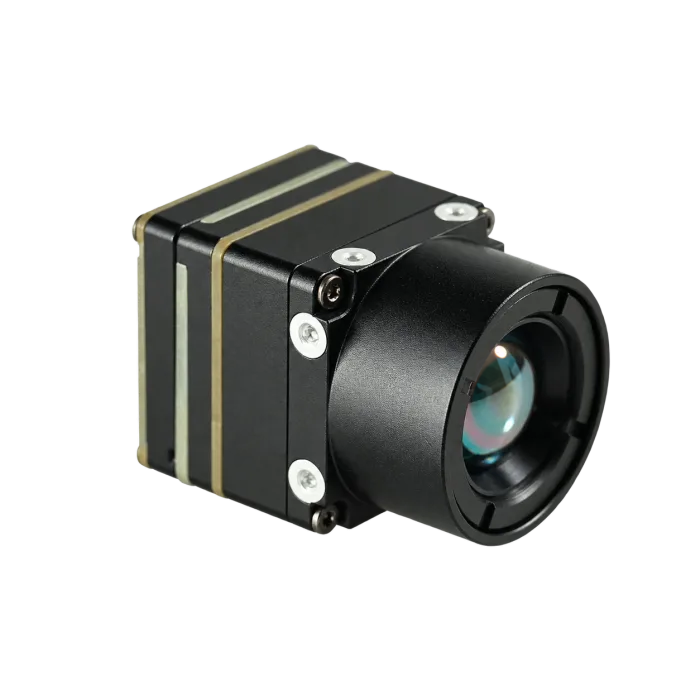
Current 9 mm AeroMini assembly photo. Lens and interface-board configuration must match the quotation; this component is not a standalone handheld instrument.
The AeroMini 640 uses a native 640×512 uncooled VOx detector with 12 µm pixels and an 8–14 µm response band. Its published NETD is ≤30 mK at 25°C, F/1.0. The non-radiometric camera is for imaging: 60 Hz is the factory default and 30 Hz is a factory option. The radiometric version is 25 Hz and enquiry only. Confirm the ordered version, lens, and output mode; these rates do not establish every interface’s simultaneous output capability.
Published dimensions are 21×21×28 mm and weight is <20 g, both excluding lens and flange. Typical module power is <0.5 W at 25°C; this is not a guaranteed complete-kit power budget. Ask for the matching assembly CAD, peak/startup current, board pinout, and firmware documentation. The product offers USB + CVBS + MIPI and Type-C + CVBS tailboards; they require different wiring references. No verified assembly mechanical drawing is reproduced here.
| Parameter | Documented AeroMini Fact / Confirmation Needed |
|---|---|
| Detector Type | Uncooled VOx (Vanadium Oxide) Microbolometer |
| Native Array Resolution | 640 × 512 pixels native; not a native 1280×1024 core |
| Pixel Pitch | 12 µm |
| Spectral Response Band | 8 µm to 14 µm (Long-Wave Infrared) |
| Frame Rate by Version | Non-radiometric: 60 Hz factory default / 30 Hz factory option. Radiometric: 25 Hz, enquiry only. Confirm rate on the selected output. |
| Thermal Sensitivity (NETD) | ≤30 mK at 25°C, F/1.0; sensitivity specification, not temperature accuracy |
| Optical Lens Options | Non-radiometric configurator: 4 / 7 / 9 / 13 / 18 / 25 / 35 / 50 mm. Documented radiometric options: 9 / 13 / 18 mm, enquiry only. Confirm the selected lens and version. |
| Video / Interface Board | USB + CVBS + MIPI or Type-C + CVBS tailboard; both-board package available. Family table lists YUV / USB / BT.656 and CVBS PAL/NTSC. Confirm board, firmware, pixel format, host support, and concurrent output rates. |
| Communication Interfaces | Family table lists UART / RS232 / RS422, board-dependent. Request the matching electrical-level and firmware command documentation; do not assume TTL compatibility. |
| Operating Voltage Rail | Family table lists board-dependent 5 V or 12 V. Illustrated POWER_IN1 (16-pin) and POWER_IN2 (26-pin) are 5 V inputs; never connect them to 12 V. Verify the selected board’s approved input. |
| Mechanical Dimensions | 21 × 21 × 28 mm, excluding lens and flange. Request matched complete-assembly CAD and mounting details. |
| Physical Weight | <20 g, excluding lens and flange. Confirm complete lens/board/cable assembly weight. |
| Procurement Evidence | Request supplier documents for the exact quoted configuration; the buyer’s procurement or qualified compliance team must assess the project and transaction requirements. |
Standalone Handheld Thermal Imager: Required Evidence
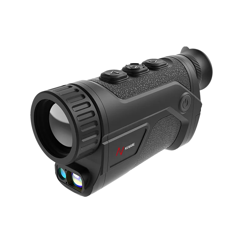
Illustrative handheld form factor only. This image does not establish a current SKU, native resolution, radiometric capability, weight, or environmental rating.
A standalone handheld instrument is appropriate when the user needs an integrated display, controls, and portable power supply for field observation or inspection. Define the actual task before comparing products: a qualitative observation viewer and a calibrated temperature-measurement camera may have different capabilities. The image illustrates the portable form factor only; no resolution or product identity is inferred from its appearance.
Request a configuration-specific datasheet and evaluate the complete device in representative conditions. Check native sampling and optics, sensitivity under stated tests, display readability, focus and glove use, battery runtime, operating mass, recording/export, and any required environmental evidence. If quantitative inspection matters, obtain accuracy, calibration, emissivity and reflected-temperature settings, and measurement-method guidance separately from an NETD claim.
| Parameter | Required Specification / Evidence to Obtain |
|---|---|
| Sensor Core Platform | Identify the detector technology and exact device configuration. State observation-only or radiometric temperature-measurement capability. |
| Spectral Response Range | Request the documented spectral response band and any optical-window limitations. |
| Resolution Configuration Paths | Request native detector resolution. Identify displayed/interpolated resolution and digital zoom separately. |
| Pixel Pitch | Request pixel pitch and verify lens-matched angular sampling for the intended feature size and working distance. |
| Frame Rate Refresh | Confirm delivered sensor, display, recording, and external-output rates for the selected mode; test motion and end-to-end delay. |
| Thermal Sensitivity (NETD) | Request NETD with scene temperature, f-number, frame rate, and processing conditions, plus typical/guaranteed status. Request radiometric accuracy separately if needed. |
| Standard Lens Options | Request focal length, f-number, horizontal/vertical field of view, focus method, transmission, and applicable calibration. |
| Instrument Weight Class | Request ready-to-use mass including the lens, battery, and required accessories; assess balance and carrying comfort. |
| Operational Focus | Validate the intended inspection or observation task, ergonomics, runtime, temperature range, and any required ingress-protection test evidence. |
| Procurement Evidence | Request supplier/configuration documents relevant to the buyer’s project and transaction review; no automatic qualification is implied. |
6. OEM Sourcing, Compliance, and RFQ Engineering Checklist
Sourcing a thermal imager core or complete instrument requires a documented optical, electrical, mechanical, and procurement baseline before an order is finalized. Use the thermal camera suppliers OEM RFQ checklist to turn system needs into questions and acceptance evidence, then confirm the exact offered configuration.
When drafting your technical RFQ submission, make sure every base is covered across these core areas:
1. Optical & Spatial Target Profiling
- ⚙️ Target Array Resolution: Specify native detector dimensions and the required sampling at the working distance. Keep a native 1280×1024 requirement distinct from a 640×512 option or an interpolated display. Budget host bandwidth, memory, storage, and processing for the chosen array and frame rate.
- ⚙️ Focal Length and IFOV: Define the smallest inspection feature, scene coverage, working-distance range, motion, and required task probability. Use IFOV and HFOV for initial geometry, then request optical MTF and representative images or tests. Use lens options documented for the actual camera version.
- ⚙️ Athermalization & Environmental Coatings: Specify the operating-temperature range, allowable focus shift, window and lens transmission, coating durability, and contamination conditions. Request evidence for the offered optical assembly; do not assume passive athermalization or a particular coating from a product family name.
2. Electrical, Hardware Bus, and Signal Architecture
- ⚙️ Primary Video Bus: Specify the delivered output format, resolution, bit depth, timing, bandwidth, electrical interface, connector, and host/driver version. Distinguish a display-ready stream from raw or calibrated data and confirm analog CVBS if required. For AeroMini, select and verify the USB + CVBS + MIPI or Type-C + CVBS board.
- ⚙️ Command & Telemetry Link: Match the actual electrical levels and transceivers, then request the firmware-specific command protocol, acknowledgement behavior, and recovery sequence. Do not connect RS232-labeled pins to TTL/CMOS UART pins without the required electrical verification.
- ⚙️ Power Rail Budget: Request approved board input voltage, steady-state and startup current, transients, polarity protection, and complete-kit consumption. AeroMini POWER_IN1 and POWER_IN2 shown in the 16-pin and 26-pin references are 5 V only, not 12 V. Its <0.5 W at 25°C is typical module consumption, not a total payload rating.
3. Mechanical Packaging, SWaP-C, and Thermal Management
- ⚙️ Payload Space Envelope: Request matched complete-assembly CAD, mounting datums, connector clearances, cable bend space, mass, and center of gravity. AeroMini’s 21×21×28 mm and <20 g exclude the lens and flange; do not use them as complete-assembly limits.
- ⚙️ Thermal Conduction Path: Define the camera-to-chassis heat path using supplier guidance. Test warm-up, temperature drift, focus, NUC/FFC behavior, and restart after environmental changes. Thermal stability is a system requirement, not proof of temperature-measurement accuracy.
- ⚙️ Environmental Enclosure Rating: Separate a core intended for a host enclosure from a finished handheld. Request evidence for the delivered enclosure, connectors, windows, battery, and accessories under the required conditions. Neither form factor alone establishes sealing, vibration, shock, or an IP rating.
4. Procurement Documentation & Transaction Review
- ⚙️ Project and Supplier Documentation: If the project includes NDAA or other procurement requirements, ask whether documents are available for the exact supplier and quoted configuration. Have the buyer’s procurement or legal team assess the evidence against the applicable project terms. A supplier statement alone is not a product qualification or eligibility decision.
- ⚙️ Transaction-Specific Review: Ask the supplier and a qualified compliance reviewer to assess the exact configuration, destination, end user, and intended use, including any documentation or authorization required for the transaction. Frame rate alone does not establish export classification, licence requirements, or eligibility.

7. Frequently Asked Questions (FAQ)
How should an entry-level thermal imager be assessed for an industrial task?
Price class alone does not determine whether a camera will succeed or fail. Start with the inspection feature size, working distance, contrast, motion, environment, and any required temperature accuracy. Compare native resolution, optical focus and MTF, sensitivity under matched conditions, temporal response, and the evidence needed for a reliable decision. Lower frame rate reduces temporal sampling but does not by itself prove motion blur, tearing, or diagnostic error. A fixed requirement for 1280×1024, 50 Hz, or one NETD threshold is not appropriate for every task. Validate representative samples and operating conditions; obtain radiometric accuracy and calibration evidence when quantitative measurement is required.
When should an engineering team choose an OEM thermal imager module over a standalone handheld camera?
Choose an OEM module when thermal sensing must be embedded in a custom host, mounting envelope, video pipeline, or application. Confirm the board-specific power, pinout, capture format, command set, software support, thermal path, and complete assembly before committing. The AeroMini 640 is a current 640×512 OEM example, with imaging and enquiry-only radiometric versions; it does not fulfill a native 1280×1024 requirement and is not a complete handheld camera. Choose a standalone handheld when an integrated display, controls, and portable power fit the field workflow. Verify its runtime, operating mass, environmental evidence, data access, and measurement capability rather than assuming them from the form factor.
How does the NETD rating impact real-world target detection in low-contrast environments?
A lower NETD can make small thermal differences easier to distinguish when cameras are compared under matched optical, thermal, temporal, and processing conditions. For example, 20 mK means 0.020 K of noise-equivalent temperature contrast under the stated test; it does not mean microkelvin detail or absolute temperature accuracy. Field detection also depends on native sampling, lens MTF and focus, contrast, motion, atmospheric transmission, and the decision task. Low NETD cannot recover a signal blocked by an obstruction or guarantee performance through fog and rain. Use the rating as one input to a representative low-contrast acceptance test, with temperature accuracy evaluated separately when needed.
📚 References & Further Reading
- Interface Standards: MIPI D-PHY; MIPI CSI-2; ITU-R BT.1120; ITU-R BT.656; A3 Camera Link. These define interface families, not CAMCUDA configuration capabilities.
- Optical and Detector Engineering: Edmund Optics: focal length and field of view; LYNRED: infrared detector technology and NETD; NIST: radiation constants.
- Core Sourcing Guide: CAMCUDA Modular Thermal Imaging Cores Catalog
- OEM Procurement Reference: Infrared Camera Module OEM Integration and Buying Guide
- Engineering RFQ Guide: Thermal Camera Suppliers OEM RFQ Checklist and Sourcing Protocol
- Current OEM Documentation: AeroMini product configuration; AeroMini datasheet; configuration-matched developer resources.