Thermal Camera Drone Modules: OEM Selection Guide for SWaP, Video Interfaces & UAV Payloads
Thermal Camera Drone Modules: OEM Selection Guide for SWaP, Video Interfaces & UAV Payloads
Integrating a high-performance thermal camera drone payload isn’t just about bolting an infrared core onto a gimbal and hoping for clean telemetry. It demands a rigorous balance between Size, Weight, and Power (SWaP), sensor sensitivity, optical resolving power, and real-time processing throughput. For robotics engineers, system integrators, and OEM drone builders, off-the-shelf commercial thermal rigs often present restrictive, closed-loop ecosystems, excessive payload mass, and painful per-unit costs. When you need to roll out proprietary, mission-specific aerial platforms—from tactical sub-250g FPV reconnaissance craft to heavy-lift industrial utility inspection hexacopters—you need uncooled Long-Wave Infrared (LWIR) cores and dual-spectrum modules selected for the required flight stack, companion computer, and radio link. Confirm the specific interfaces, software and control integration before committing to a payload.
Here’s the deal: designing an optimal aerial thermal architecture means digging past surface-level marketing spec sheets. You have to evaluate the physics of uncooled Vanadium Oxide (VOx) focal plane arrays, real-world Noise Equivalent Temperature Difference (NETD), lens Modulation Transfer Function (MTF), and DORI (Detection, Recognition, Identification) optical envelopes. On top of that, you’ve got to pick the right video transport protocols—balancing analog CVBS integration against digital streaming via MIPI CSI-2 or USB Video Class (UVC), with end-to-end latency measured on the selected hardware—all while wrestling with electromagnetic interference (EMI), motor vibration, and edge compute limits.
Technical author: Daniel · Hardware Support
Table of Contents
- 👉 1. LWIR Core Physics & Sensor Architectures for UAV Payloads
- 👉 2. Optics, Focal Length & DORI Calculations for Aerial Platforms
- 👉 3. SWaP-C Optimization & Electrical Integration on Airframes
- 👉 4. Video Bus Protocols & Telemetry Interfaces: MIPI, USB, CVBS, and Serial
- 👉 5. Dual-Spectrum Sensor Fusion & Onboard Edge AI Tracking
- 👉 6. Autopilot Integration & Ground Control Workflows (ArduPilot / BetaFlight / PX4)
- 👉 7. Comparative OEM Hardware Showcase: Evaluation of 640×512 Cores & AI Modules
- 👉 8. Comprehensive OEM Integration & Sourcing FAQ
1. LWIR Core Physics & Sensor Architectures for UAV Payloads
Thermal imaging payloads deployed on unmanned aerial systems operate smack in the middle of the Long-Wave Infrared (LWIR) atmospheric transmission window (8 to 14 µm). Radiation in this band is emitted directly by physical objects as a direct function of their absolute temperature and surface emissivity. This physical reality allows a thermal camera drone to pull off reconnaissance, search and rescue (SAR), wildlife tracking, and powerline inspection through absolute pitch darkness, light foliage, maritime haze, and industrial smoke without shining an active spotlight on the target.
When you’re designing hardware for flight, the detector architecture dictates everything down the line: lens size, gimbal motor selection, processing overhead, and flight duration.
Microbolometer Material Systems: VOx vs. a-Si
At the center of every modern thermal core sits a focal plane array (FPA) of tiny microbolometers. When selecting an OEM sensor core off the shelf or drafting requirements for a vendor, you run into two main semiconductor chemistries:
- ⚙️ Vanadium Oxide (VOx): This is the uncontested industry standard for tactical and industrial airborne systems. VOx delivers a high Temperature Coefficient of Resistance (TCR), typically hovering around -2% to -3% per Kelvin. In plain English: it yields noticeably higher thermal sensitivity, lower 1/f flicker noise, and snappy thermal time constants (8 to 12 ms). That speed is vital when the drone is dealing with high mechanical vibration and fast yaw rates during dynamic maneuvers.
- ⚙️ Amorphous Silicon (a-Si): A thin-film alternative that benefits from standard, high-yield CMOS foundry fabrication. While it can lower unit costs, a-Si historically struggles with higher bulk flicker noise and lower native sensitivity. To pull a usable signal-to-noise ratio out of an a-Si sensor, optical engineers must use beefier lenses with wider apertures (F/# ≤ 1.0), adding dead weight straight to your gimbal assembly.
Organizations like Optica track ongoing research into microbolometer thin-films, documenting gains in pixel micro-machining, thermal isolation legs, and quantum absorption efficiency.
Pixel Pitch Dynamics: 12 µm vs. 17 µm
The industry shift from 17 µm down to 12 µm pixel pitch has been a massive win for airframe integration. Because the overall silicon die area scales with the square of the pixel pitch, a 640×512 resolution sensor built on a 12 µm pitch trims the total detector footprint by nearly 50% compared to an older 17 µm die with the exact same pixel count. In the shop, that translates to two direct engineering wins:
- ✅ Slimmer Optical Trains: Hitting a target Field of View (FOV) on a 12 µm sensor requires a shorter focal length lens. This cuts the overall mass and volume of expensive Germanium or Chalcogenide glass elements by up to 40%.
- ✅ Lower Gimbal Inertia: Shorter, lighter lenses reduce the rotational moment of inertia around pitch and yaw axes. That means you can step down your brushless gimbal motors (say, from 2806-size down to 2204-size), slashing steady-state holding current and putting flight minutes back into your battery pack.
Thermal Sensitivity (NETD) in Real Flight Environments
Noise Equivalent Temperature Difference (NETD) defines the temperature delta required to produce an output signal equal to the detector’s internal noise floor (SNR = 1), measured in milliKelvins (mK). Standard industrial-grade cores are typically rated at NETD ≤ 40 mK (bench-tested at 25°C with an F/1.0 lens).
Look, bench specs can be deceiving. Once an aircraft is cruising at 15 m/s at 100 meters AGL, atmospheric attenuation, ground clutter washout, and aerodynamic boundary layer cooling over the payload lens degrade your thermal gradient. An NETD ≤ 40 mK ensures that subtle thermal details—a hair-line crack in a solar cell, moisture trapped under membrane roofing, or a target partially hidden under tree canopy—stay sharp and actionable rather than blending into background noise.
2. Optics, Focal Length & DORI Calculations for Aerial Platforms
Matching the focal length of an infrared optic to your operational flight ceiling is an exercise in managing trade-offs: you are constantly balancing spatial coverage (Field of View) against the resolving power needed to spot anomalies. The DRI (Detection, Recognition, Identification) example below uses illustrative pixel-count assumptions for geometric comparison; these are not guaranteed recognition thresholds for a person, algorithm or camera:
- 📌 Detection (1.5 pixels on target): The example assumes this sampling threshold for detecting the presence of an object; actual detection depends on contrast and test conditions.
- 📌 Recognition (6.0 pixels on target): The example uses this threshold for a recognition estimate; classification performance must be tested with representative scenes.
- 📌 Identification (12.0 pixels on target): The example uses this threshold for an identification estimate; it does not guarantee that any particular detail will be resolved.
Instantaneous Field of View (IFOV) and Ground Sampling Distance (GSD)
The angular resolution of an individual pixel is dictated by the Instantaneous Field of View (IFOV), expressed in milliradians (mrad):
IFOV (mrad) ≈ 1000 × [Pixel Pitch (p in mm) / Focal Length (f in mm)]
To calculate the physical Ground Sampling Distance (GSD) projected onto flat terrain from an aircraft at an Above Ground Level (AGL) altitude H with a nadir (straight down) gimbal angle:
GSD (m/pixel) ≈ H (m) × IFOV (mrad) / 1000 = H × (p / f)
Illustrative DRI Geometry Calculation:
Let’s run the numbers on a 640×512 LWIR module with a 12 µm pitch paired with a 9.1 mm focal length lens (p = 0.012 mm, f = 9.1 mm):
IFOV ≈ 1000 × 0.012 / 9.1 ≈ 1.3187 mrad
Calculating the optical envelope for a standard vehicle target (critical dimension W = 2.3 meters):
- ⚙️ Detection Range (N_crit = 1.5 px): R_detect = 2.3 / (0.0013187 × 1.5) ≈ 1,162 meters
- ⚙️ Recognition Range (N_crit = 6.0 px): R_recog = 2.3 / (0.0013187 × 6.0) ≈ 290 meters
- ⚙️ Identification Range (N_crit = 12.0 px): R_ident = 2.3 / (0.0013187 × 12.0) ≈ 145 meters
| Target Type | Critical Dimension | Detection (1.5 px) | Recognition (6.0 px) | Identification (12.0 px) |
|---|---|---|---|---|
| Human Target | 0.5 m | ~252 m | ~63 m | ~31 m |
| Vehicle Target | 2.3 m | ~1,162 m | ~290 m | ~145 m |
| Maritime Vessel | 5.0 m | ~2,527 m | ~631 m | ~315 m |
Calculation limits: These ranges are geometric estimates using the stated target dimensions and pixel thresholds. They do not include atmosphere, contrast, optics, motion blur, stabilization or algorithm performance, and are not measured AeroMini or VisionCube detection guarantees. Use the CAMCUDA thermal imaging calculator to compare sensor, lens and distance assumptions, then validate the chosen payload in its operating conditions.
If you’re retrofitting an existing airframe or engineering modular nose-cones, run these optical calculations early so you don’t end up with an optic that’s blind at your standard cruise ceiling. For a complete teardown on retrofitting legacy airframes with modular LWIR optics, take a look at our LWIR Thermal Camera OEM Retrofit Guide.
3. SWaP-C Optimization & Electrical Integration on Airframes
In the drone world, payload mass is the enemy of flight endurance. On a typical multi-rotor platform, tacking on an extra 50 grams can cost you 2 to 4 minutes of hover time, depending on your disc loading and motor kV ratings. Every milliwatt and gram counts.
Power Delivery & Low-Noise Regulation
Thermal microbolometers are notoriously sensitive to raw power rails. Voltage ripple and high-frequency switching noise from Electronic Speed Controllers (ESCs) and brushless motors will show up immediately as horizontal rolling bands, micro-jitter, or fixed-pattern noise across your thermal feed.
- ⚙️ Voltage Supply Rails: Match power to the exact interface board. On the illustrated AeroMini USB + CVBS + MIPI board, POWER_IN1 and POWER_IN2 are 5 V inputs; do not connect them to 12 V. AeroMini publishes <0.5 W typical module consumption at 25°C, not a complete-payload budget. The VisionCube processing-board reference specifies 9–16 V input; confirm the complete kit power requirement separately.
- ⚙️ Filtering & Grounding: Always run core power through a dedicated step-down DC-DC buck converter fitted with low-ESR ceramic bypass capacitors and a ferrite bead filter to choke out motor switching spikes above 50 kHz. Set up a single-point star ground topology to prevent ground loops between the video transmitter and thermal core.
Thermal Dissipation & Convective Cooling
Uncooled microbolometers rely on continuous Non-Uniformity Correction (NUC) routines to zero out internal sensor drift. Rapid, uneven temperature shifts across the sensor housing degrade calibration and radiometric fidelity.
- ⚙️ Conduction Paths: Anchor the thermal core’s aluminum housing directly to the gimbal arm or airframe using thermal interface gap pads (thermal conductivity k ≥ 3.0 W/m·K) to sink heat away from the electronics.
- ⚙️ Rotor Wash Convection: Assess airflow and housing temperature over the full duty cycle, including hover and ground operation. AeroMini publishes an operating range of −40°C to +80°C; airflow alone does not establish that a complete payload meets that range.
4. Video Bus Protocols & Telemetry Interfaces: MIPI, USB, CVBS, and Serial
Hooking an OEM thermal core into your avionics and telemetry stack requires matching the hardware interface to your latency thresholds and processing requirements.
| Interface Type | Video / Command Format | Latency Validation | Cable / Board Constraint | Primary Application Fit |
|---|---|---|---|---|
| MIPI CSI-2 | Output format and lane configuration depend on the module, board and firmware | Measure the complete camera-to-host pipeline | Confirm connector, routing, signal integrity and host receiver | Embedded board-to-board vision |
| USB / UVC | Supported image formats depend on firmware; UVC does not establish radiometric data | Measure capture, buffering and display delay | Confirm board, cable, host driver and negotiated format | Companion-computer image capture |
| CVBS (Analog) | PAL / NTSC where supported by the selected board | Measure camera, transmitter, receiver and display together | Match video standard, grounding and connection guide | Analog monitoring and FPV video |
| RS-422 / UART | Control commands; baud rate and electrical levels are configuration-specific | Command timing is distinct from video latency | UART and RS-422 use different electrical signaling | Supported camera control and configuration |
Digital vs. Analog Video Topologies
- ⚙️ MIPI CSI-2: Useful for embedded board-to-board integration when the camera output and host receiver match. Confirm the pixel format, lane configuration, clocking and software support. The standard AeroMini configuration does not provide RAW or minimally processed video; the product FAQ requires a separate customization assessment for that requirement.
- ⚙️ USB / UVC: A practical evaluation path when the selected board and host support the same video format. Confirm capture software, controls and frame rate for the supplied firmware. A viewable thermal stream does not by itself provide calibrated temperatures or prove driverless support on every host.
- ⚙️ CVBS (Composite Video): PAL/NTSC video can fit an analog monitoring chain when supported by the selected tailboard. End-to-end delay includes the camera, transmitter, receiver and display; verify it on the intended build rather than inferring a fixed delay from the connector.
AeroMini Board and Connector References
These two references apply to the illustrated USB + CVBS + MIPI tailboard. Match the delivered revision and use the full signal table before wiring. They are not the Type-C + CVBS pinout or a complete-assembly mechanical drawing.
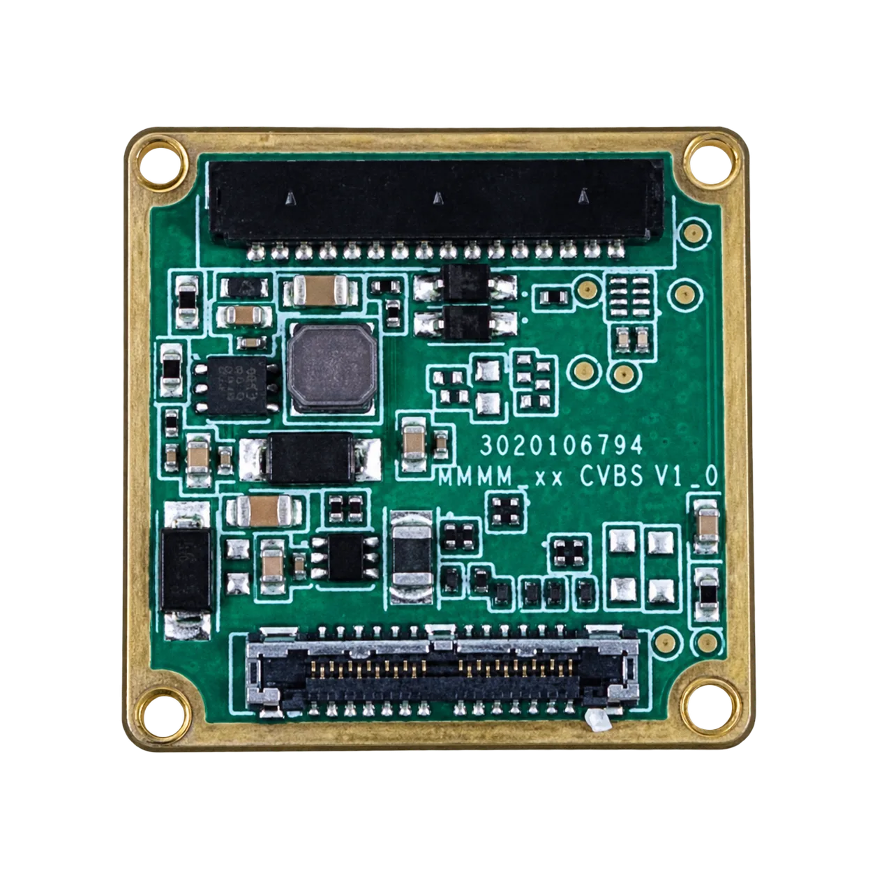

AeroMini software and control resources: The product FAQ identifies USB-SDK.zip as the source of Linux drivers, examples and the SDK. The public AeroMini technical documentation folder lists that archive, CAMCUDA_AeroMini_640_USB_User_Manual_EN.pdf, CAMCUDA_AeroMini640_Integrated_EN.pdf, USB Client Software.zip, a 7 mm STEP file and CV Serial port. Match the board, firmware, host, video format and factory frame rate before integration. These are AeroMini resources; they do not establish VisionCube software compatibility. The 7 mm STEP file is not a universal drawing for every lens assembly.
Command & Control Buses: RS-422 and UART
To send runtime commands—like triggering a flat-field NUC shutter, kicking in digital zoom, flipping palettes (White Hot, Black Hot, Ironbow), or targeting regions of interest—you need dependable serial lines:
- ⚙️ UART: Simple and effective for short, clean board-to-board traces inside an enclosed gimbal pod.
- ⚙️ RS-422 Differential: The professional choice when signals have to route through continuous slip rings or across longer airframe spans. The balanced differential signaling shrugs off heavy EMI from nearby motor leads and high-power telemetry antennas.
Sensor manufacturers like Hikmicro use standard serial protocols across their industrial cores to handle lens focus positions, palette swaps, and internal calibration routines.
5. Dual-Spectrum Sensor Fusion & Onboard Edge AI Tracking
Modern aerial operations need more than basic single-spectrum thermal feeds. LWIR gives you thermal contrast at night, but it cannot resolve visible textures, read license plates, or see through glass. Pairing a visible daylight (EO) sensor with an uncooled LWIR core delivers a dual-spectrum payload that stays operational 24/7 across daylight, shadow, pitch darkness, and heavy fog.
Dynamic Image Alignment and Picture-in-Picture (PIP)
Dual-spectrum architectures may present both streams using PIP or combine image content using fusion. These are different functions; the current VisionCube brochure documents PIP, while any required alignment or edge-fusion behavior needs configuration-specific confirmation:
- ⚙️ Picture-in-Picture (PIP): A straightforward windowed overlay where the thermal feed is centered inside the wide-angle visible frame (or vice versa), maintaining overall situational awareness while tracking thermal hotspots.
- ⚙️ Spectral Fusion (Edge Blending): High-frequency edge data extracted from a 1080p visible sensor is overlaid directly onto the lower-resolution 640×512 thermal stream. You get the heat signature along with structural contours, legible markings, and fine environmental detail.
Deep Learning Inference at the Edge
Running neural network models onboard can reduce dependence on a downlink for processing. For a current system-level comparison, VisionCube DT Pro combines dual visible cameras, 6 TOPS processing and 640 × 512 thermal imaging. A TOPS figure alone does not specify detection range, tracking accuracy, latency or application support; assess those against the selected hardware and software.
- ✅ Multi-Class Target Tracking: Define the classes, object sizes, scene conditions and false-alarm limits for the application, then evaluate a sample. The current VisionCube listing does not establish the earlier module’s distance, minimum-pixel, track-count or processing-delay claims.
- ✅ Occlusion Handling & Target Recovery: Test partial occlusion, loss of view and reacquisition with the selected software. Supplier footage containing tracking overlays is not a guarantee that a specific configuration will retain or recover every target.
For compact platforms that need only coarse heat-pattern detection, a lower-resolution thermal sensor may reduce data and integration demands. Check the pixel coverage, total payload mass and power needed for the task; low resolution alone does not establish suitability for a particular aircraft.
6. Autopilot Integration & Ground Control Workflows (ArduPilot / BetaFlight / PX4)
If the application needs gimbal coordination, georeferencing or automated pointing, plan the interface between the imaging payload, companion computer and flight controller. The table is an architecture checklist, not a claim that AeroMini or VisionCube directly supports ArduPilot, PX4 or BetaFlight. Confirm message definitions, electrical interfaces, control software and failsafe behavior for the exact build.
| Integration Parameter | ArduPilot / PX4 Architecture Review | BetaFlight / FPV Architecture Review |
|---|---|---|
| Telemetry / Control | Confirm supported MAVLink messages and bridge software | Confirm radio, MSP/CRSF support and command mapping |
| Video Path | Companion capture/encoding and compatible downlink as required | Compatible video transmitter and receiver as required |
| Geotagging & Metadata | Implement and validate time-aligned position/attitude metadata | Confirm the selected OSD and telemetry implementation |
| Imaging Control Loop | Verify payload API, gimbal driver and failsafe integration | Confirm supported controls and safe behavior on link loss |
Telemetry Standards: MAVLink V2 and CRSF
- ⚙️ MAVLink V2 Protocol: An integration option for supported ArduPilot/PX4 workflows. Camera events, position and attitude data must be explicitly supported, synchronized and recorded by the implementation; a MAVLink connection does not automatically inject precise EXIF metadata into thermal images.
- ⚙️ CRSF (Crossfire Protocol): Radio-control integration must be implemented and verified for the selected controller and payload. Palette, PIP and other camera commands require documented mappings; their availability cannot be inferred from the use of CRSF elsewhere in the aircraft.
Closed-Loop Visual Servoing
A visual-servoing implementation may use image-space offsets to command a gimbal or other pointing mechanism through a supported controller. This requires a documented output interface, tested control software and appropriate failsafes. Neither the thermal core nor a 6 TOPS processor establishes a target-speed rating or direct flight-control compatibility.
7. Comparative OEM Hardware Showcase: Evaluation of 640×512 Cores & AI Modules
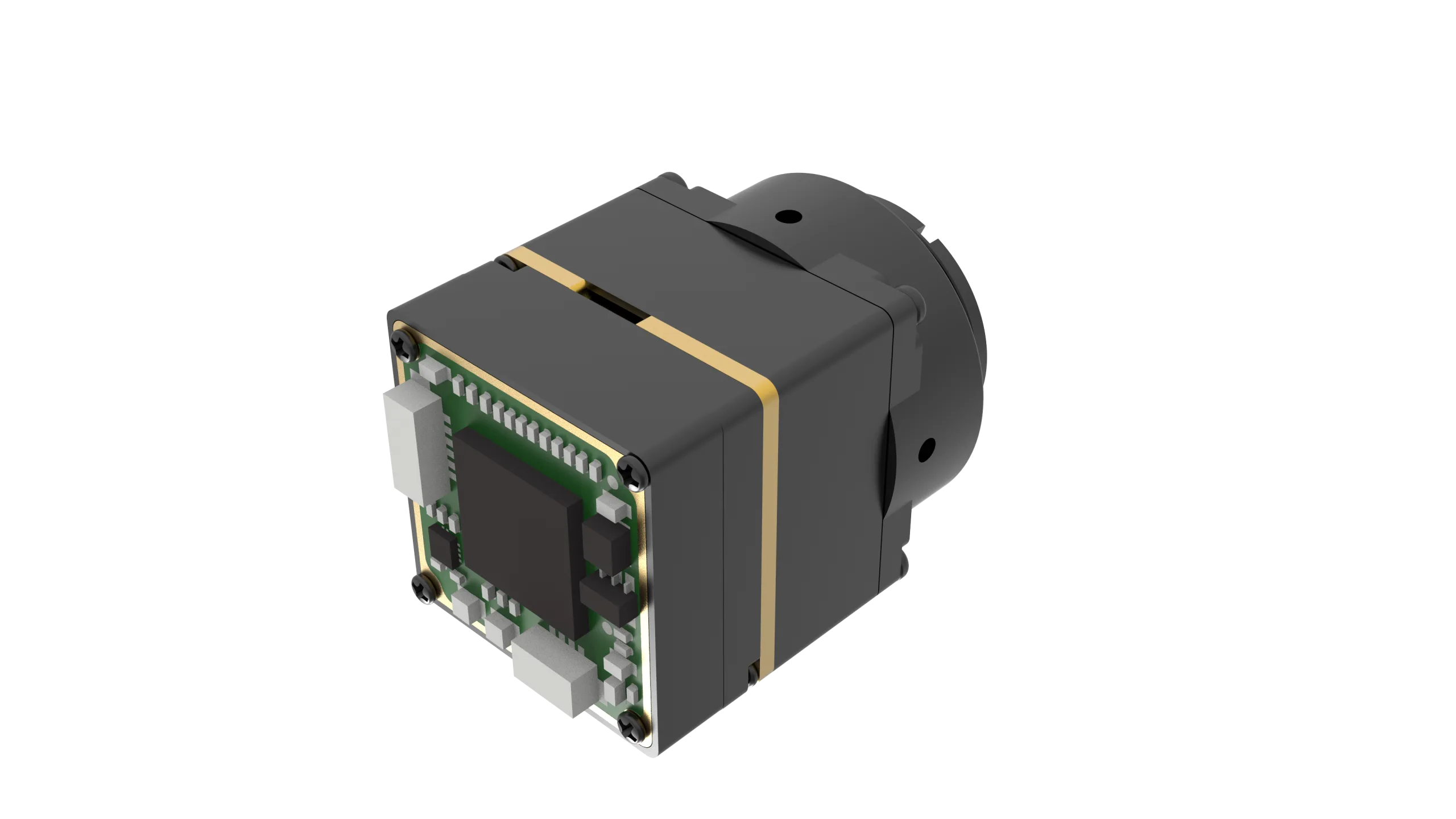
The following comparison covers two different integration levels: AeroMini 640 for thermal-image capture, and VisionCube DT Pro for a visible-plus-thermal processing assembly. Compare the complete bill of materials, software requirements and measured payload budget before choosing between them.
CAMCUDA AeroMini 640 LWIR Thermal Camera Module
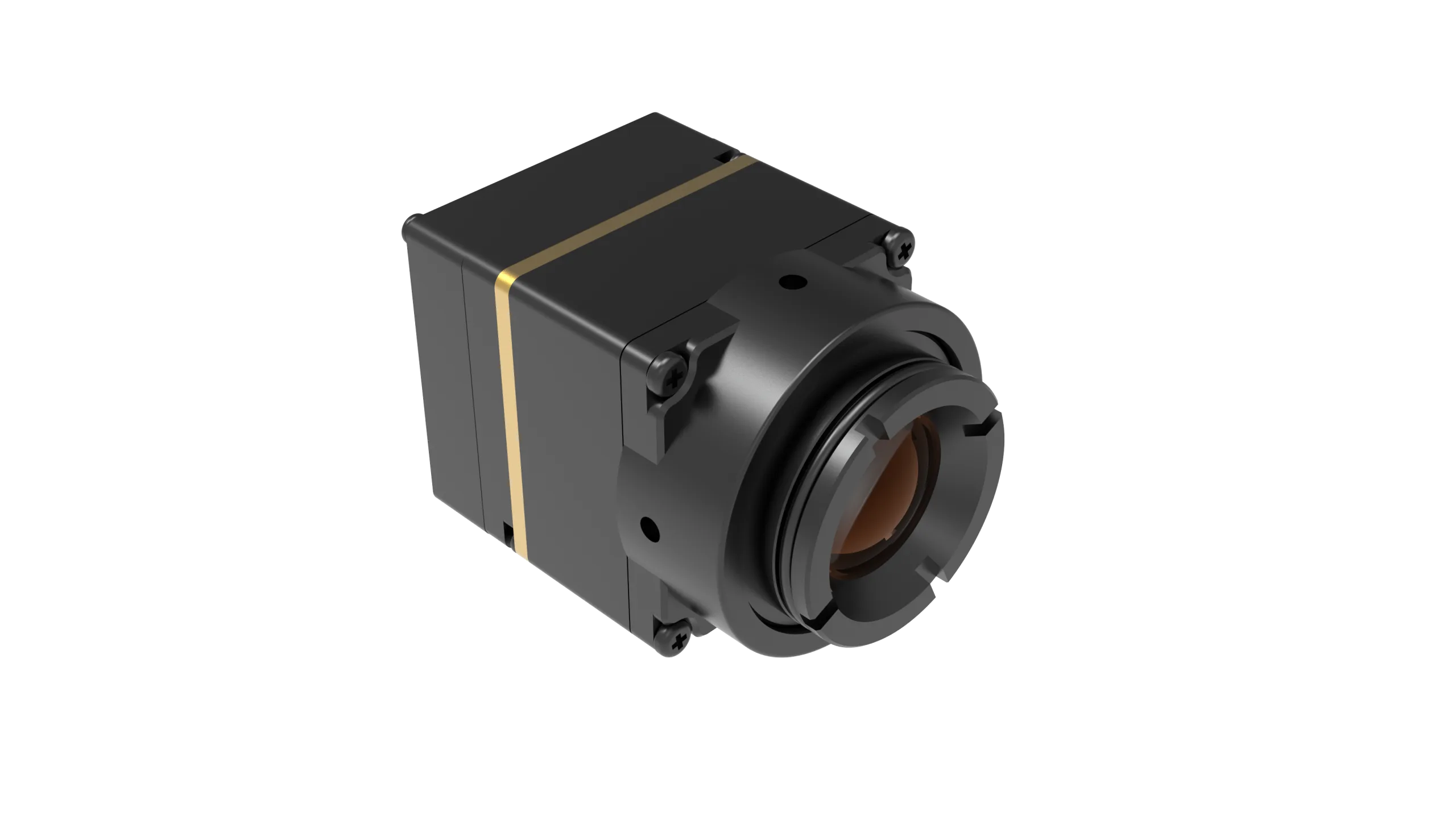
The CAMCUDA AeroMini 640 is a 640 × 512 uncooled VOx module for OEM thermal-image capture. The standard non-radiometric configuration provides images of relative heat patterns; calibrated temperature measurement is a separate 25 Hz radiometric configuration available by enquiry. Select the lens and tailboard together, then verify the full assembly mass, power, dimensions and host interface.
| Detector & Imaging | |
|---|---|
| Model / Resolution | CAMCUDA AeroMini 640 | 640 × 512 |
| Detector / Pixel Pitch / Band | Uncooled VOx | 12 μm | 8–14 μm LWIR |
| Non-radiometric Frame Rate | 60 Hz default / 30 Hz factory option; specify before ordering |
| Radiometric Configuration | 25 Hz; availability enquiry. Confirm measurement accuracy, data format and interface separately |
| Thermal Sensitivity (NETD) | ≤30 mK at 25°C, F/1.0 |
| Interface Selection | |
| Non-radiometric Tailboards | USB + CVBS + MIPI; Type-C + CVBS; or both tailboards with the quoted cables |
| Data & Host Support | Match output format, firmware and host. Standard configuration does not provide RAW/minimally processed video; customization requires separate assessment |
| Control | Board-dependent; use the matched serial-command and electrical documentation |
| Electrical, Mechanical & Environmental | |
| Illustrated Board Power | POWER_IN1 / POWER_IN2 are 5 V inputs on the USB + CVBS + MIPI board; do not apply 12 V or use this pin map for Type-C |
| Typical Module Power | <0.5 W at 25°C; complete-kit and aircraft consumption require separate measurement |
| Module Weight & Dimensions | <20 g | 21 × 21 × 28 mm, excluding lens and flange. Confirm complete assembly dimensions and mass |
| Operating / Storage Temperature | −40°C to +80°C / −50°C to +85°C; 5–95% non-condensing humidity |
CAMCUDA AI VisionCube DT Pro: Dual Visible + 640 Thermal
The CAMCUDA AI VisionCube DT Pro combines wide-angle and telephoto visible imaging, 6 TOPS processing and 640 × 512 thermal imaging for civilian inspection and observation. It is a system-level comparison with the AeroMini core, not a drop-in replacement. The current listing provides configuration and component references; verify the supplied camera assembly, software, power and integration support for the intended application.
| Configuration & Processing | |
|---|---|
| Selected Configuration | AI VisionCube DT Pro: dual visible cameras + 640 thermal imaging |
| AI Processing / Display | 6 TOPS | Picture-in-picture documented in the supplied brochure |
| Family Boundaries | S / D: no thermal camera. ST / DT: 384 × 288 at 25 Hz. ST Pro / DT Pro: 640 × 512 at 50 Hz |
| Performance Validation | Supplier demonstration overlays are not configuration-specific guarantees of range, speed, latency, track count or recovery |
| Visible & Thermal Cameras | |
| Visible Output | 1920 × 1080 at 30 Hz |
| Visible Optics / FOV | 3.9 mm wide-angle: 72° H × 45° V; 12 mm telephoto: 26° H × 15° V |
| DT Pro Thermal Output | 640 × 512 at 50 Hz | 12 μm | 8–14 μm LWIR |
| DT Pro Thermal Optics / Interface | 9.1 mm | 45.9° H × 36.9° V | USB listed for the thermal camera |
| Radiometry | The current brochure does not specify calibrated temperature range or accuracy; do not assume radiometric capability |
| Component References & Integration | |
| Processing Board | 9–16 V input | 38 × 38 × 29 mm | 43.8 g | 25.5 × 25.5 mm mounting pattern |
| DT Pro Thermal Camera | 26 × 26 × 21.1 mm; ≤23 g, excluding lens and connectors |
| Complete Kit | Component values above are not total assembly dimensions or mass. Confirm total power, included parts and mounting drawing |
| Software / Flight Controller | Confirm configuration-specific SDK/API and controller integration. No direct ArduPilot, PX4 or BetaFlight compatibility is established here |
8. Comprehensive OEM Integration & Sourcing FAQ
How can I integrate a thermal camera into a custom UAV or sub-250g build without compromising flight time?
Which video output protocol is optimal for low-latency drone thermal video transmission?
Is it more cost-effective to buy an enterprise thermal drone or build around an OEM thermal module?
Compare total development and ownership cost rather than module price alone. AeroMini 640 can suit a custom thermal-imaging path, while VisionCube DT Pro adds dual visible imaging and onboard processing at a different integration level. Include optics, mounting, power conversion, software work, calibration needs, testing and support in the budget. Confirm SDK access, permitted software changes and flight-controller integration for the selected configuration; an open telemetry protocol does not guarantee payload compatibility or eliminate development costs.
📚 References & Further Reading
- 👉 Industry Standard: Optica (Advances in Microbolometer & Infrared Optical Physics)
- 👉 Sensor Architecture: Hikmicro (Industrial Thermal Imaging Modules & Cores)
- 👉 Related Guide: CAMCUDA Engineering Memo: LWIR Thermal Camera OEM Retrofit Guide
- 👉 Lower-Resolution Sensing: Coarse heat-pattern detection can use fewer pixels, but confirm target coverage and complete-payload requirements before choosing a sensor.
- 👉 Compliance & Terms: CAMCUDA Privacy Policy & Sourcing Standards