Inexpensive IR Camera Guide: Selecting Cost-Effective OEM Thermal Cores
Inexpensive IR Camera Guide: Selecting Cost-Effective OEM Thermal Cores
Integrating infrared vision into commercial imaging systems, unmanned aerial vehicles (UAVs), robotics, perimeter security, and industrial monitoring arrays historically demanded massive capital investments. For optical engineers, hardware architects, and original equipment manufacturers (OEMs), procuring an inexpensive ir camera core previously meant making severe technical compromises—settling for low-resolution 32×24 thermopile arrays, high-latency 9 Hz sensor throttling, or delicate consumer-tier dongles completely unsuited for continuous industrial duty cycles. Fortunately, the semiconductor physics and production economics of microbolometers have evolved dramatically over the last decade.
Recent breakthroughs in high-yield 12 µm Vanadium Oxide (VOx) wafer-level packaging (WLP), combined with high-density chalcogenide infrared optics and cost-effective edge-AI compute engines, have fundamentally reshaped the marketplace. High-performance, uncooled long-wave infrared (LWIR) camera modules operating at 640×512 resolution and smooth 50 Hz refresh rates are now accessible at prices well within reach for mid-tier commercial hardware budgets. This shift enables vision engineers to deploy true radiometric thermal sensing and autonomous edge-tracking capabilities directly on compact platforms without blowing out total bill-of-materials (BOM) costs.
Here’s the deal: navigating the budget-conscious end of the thermal imaging market demands rigorous technical due diligence. Cost reductions in thermal cores can introduce hidden engineering pitfalls: degraded Noise Equivalent Temperature Difference (NETD), spatial non-uniformity drift, thermal baseline drift across operational temperatures, low-transmission optics, or locked interface firmware. This guide delivers a comprehensive, engineering-level breakdown of infrared sensor physics, hardware trade-offs, optical calculations, integration interfaces, and real-world OEM benchmarks to help you select and integrate the optimal cost-effective thermal camera core for your application.
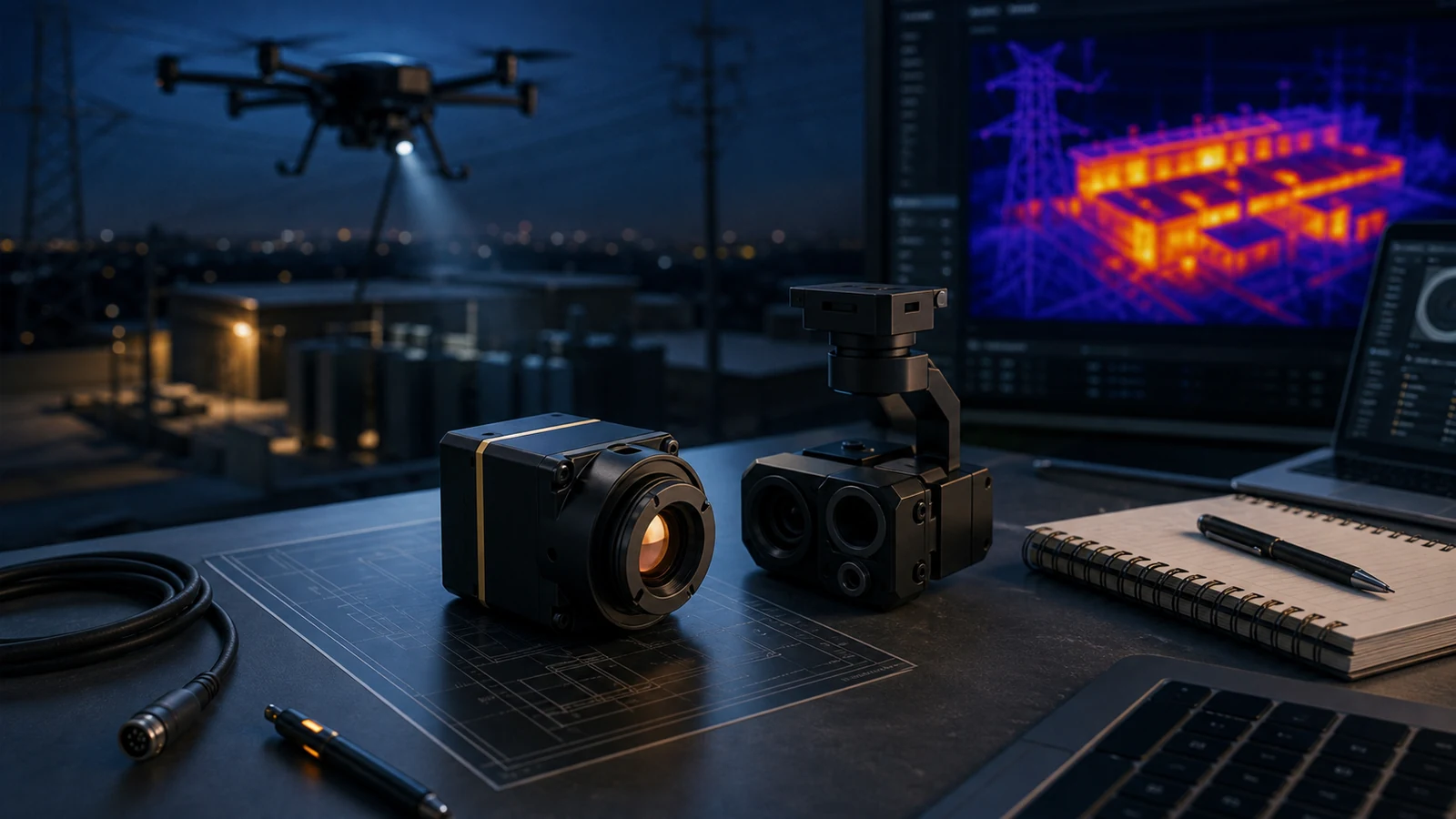
In the shop, we see design teams get burned all the time by confusing marketing terminology or glossing over thermal dissipation mechanics. Whether you are building an airborne search payload or a factory-floor machine vision rig, understanding the sensor physics and readout electronics upfront is the only way to avoid costly board respins.
Table of Contents
- 👉 1. Demystifying the Inexpensive IR Camera: NIR vs. SWIR vs. MWIR vs. LWIR
- 👉 2. Sensor Architectures: Thermopiles vs. a-Si vs. High-Yield VOx Microbolometers
- 👉 3. Key Engineering Trade-Offs: SWaP-C, NETD, Frame Rates, and Video Protocols
- 👉 4. Edge-AI Compute and Dual-Spectrum Electro-Optical/Infrared (EO/IR) Payloads
- 👉 5. Featured OEM Hardware Benchmarks & Technical Specifications
- 👉 6. Optics Selection, Germanium Alternatives, and Johnson’s Criteria Calculations
- 👉 7. OEM Integration Blueprint: Power Conditioning, Thermal Dissipation, and NUC Control
- 👉 8. Deep-Dive Engineering FAQ
1. Demystifying the Inexpensive IR Camera: NIR vs. SWIR vs. MWIR vs. LWIR
In OEM component sourcing, the phrase inexpensive ir camera often creates major confusion across engineering disciplines. Sales literature frequently groups silicon night-vision cameras and microbolometers under the same broad “infrared” umbrella. Look: the infrared spectrum spans four distinct wavebands, each governed by radically different semiconductor physics, production processes, and optical material constraints:
- 🔍 Near-Infrared (NIR, 0.75–1.0 µm): NIR imaging uses standard silicon CMOS image sensors with the infrared-cut filter pulled off. When paired with active light-emitting diodes (LEDs) operating at 850 nm or 940 nm, silicon sensors capture reflected infrared photons. Let’s be clear: NIR systems do not detect heat. If the target falls outside the active illuminator beam, or if heavy fog or smoke scatters the light, the sensor yields zero contrast.
- 🔍 Short-Wave Infrared (SWIR, 1.0–2.5 µm): SWIR imaging relies on Indium Gallium Arsenide (InGaAs) focal plane arrays. SWIR behaves similarly to visible light in how it reflects off surfaces, but penetrates haze and enables specialized industrial sorting (e.g., moisture detection, silicon wafer inspection). High sensor fabrication costs keep SWIR arrays well outside typical low-cost hardware budgets.
- 🔍 Mid-Wave Infrared (MWIR, 3.0–5.0 µm): MWIR sensors use photon detectors (such as Indium Antimonide or Mercury Cadmium Telluride) that require active cryocooling to liquid nitrogen temperatures (~77 K). While they offer long-range sensitivity, cryogenic Stirling coolers make MWIR systems costly, bulky, and subject to regular maintenance cycles.
- 🔍 Long-Wave Infrared (LWIR, 8.0–14.0 µm): LWIR uncooled thermal imaging captures the passive blackbody radiation emitted by all physical matter above absolute zero ($0\text{ K}$), as described by Planck’s radiation law and the Stefan-Boltzmann law ($M = \epsilon \sigma T^4$). True uncooled LWIR cameras operate in complete darkness ($0.000\text{ lux}$), cut straight through atmospheric smoke, dust, and light foliage, and cannot be blinded by oncoming headlights or direct solar glare.
When selecting a cost-effective thermal camera core for robotics, drones, or automated monitoring, design teams are almost always looking for uncooled Long-Wave Infrared (LWIR) microbolometers. These modules deliver true thermal vision and thermographic data without the high cost and maintenance headaches of cooled detectors.
2. Sensor Architectures: Thermopiles vs. a-Si vs. High-Yield VOx Microbolometers
Choosing an inexpensive infrared core requires balancing price against sensor resolution, thermal sensitivity, and temporal stability. In the field, hardware designers generally weigh three primary sensor architectures:
Low-Cost Thermopile Arrays (Low-Fidelity Grid Arrays)
Thermopiles operate by connecting multiple thermocouples in series, converting thermal gradients into differential electrical voltage through the Seebeck effect. These sensors feature extremely low manufacturing costs and simple integration requirements. However, their pixel count is tightly constrained (typical resolutions range from 32×24 to 80×62 pixels), their thermal time constant is slow ($\tau > 15\text{ ms}$), their frame rates rarely exceed 4–16 Hz, and their Noise Equivalent Temperature Difference is relatively high ($\text{NETD} > 100\text{ to } 250\text{ mK}$). While workable for basic consumer HVAC presence sensors or spot thermometers, thermopiles lack the spatial fidelity required for edge machine learning, security classification, or autonomous mobile robot navigation.
Amorphous Silicon (a-Si) Microbolometers
Amorphous Silicon was long favored for budget thermal imaging because it integrates cleanly with standard CMOS silicon semiconductor fabrication lines. In an a-Si sensor, incident thermal radiation alters the bulk resistance of an amorphous silicon thin film suspended over readout integrated circuits (ROIC). While a-Si cores lower manufacturing costs, they exhibit lower Temperature Coefficients of Resistance ($\text{TCR} \approx -1.5\%/\text{K}$ to $-2.0\%/\text{K}$) and higher structural $1/f$ noise. Maintaining thermal sensitivity below 50 mK is tough without lengthy averaging steps that introduce unacceptable motion blur on moving targets.
Vanadium Oxide (VOx) Microbolometers (Modern High-Yield Standard)
Vanadium Oxide (VOx) has emerged as the clear winner for high-performance, cost-effective thermal imaging. VOx thin-film resistors offer a high Temperature Coefficient of Resistance ($\text{TCR} \approx -2.5\%/\text{K}$ to $-3.5\%/\text{K}$), lower electronic $1/f$ noise, and faster thermal time constants ($\tau \le 8\text{ to } 10\text{ ms}$). Advances in 12 µm micro-machining and Wafer-Level Packaging (WLP)—where individual dies are vacuum-sealed at the wafer level before dicing—have driven down production costs dramatically. OEMs can now source 640×512 VOx microbolometers with high thermal sensitivity ($\text{NETD} \le 30\text{ mK}$) at price points once limited to low-resolution a-Si cores.
3. Key Engineering Trade-Offs: SWaP-C, NETD, Frame Rates, and Video Protocols
Specifying a budget-friendly thermal imaging core requires balancing five core technical parameters: size, weight, power, cost, and optical performance (SWaP-C).
1. Noise Equivalent Temperature Difference (NETD) and Sensitivity
NETD measures thermal sensitivity, representing the smallest target temperature differential an infrared sensor can resolve before electronic and thermal noise obscures the signal. It is expressed in millikelvins (mK), measured at a specific optical aperture (typically F1.0) and ambient reference temperature ($25^\circ\text{C}$):
- ⚠️ Budget/Consumer Grade ($\text{NETD} \ge 50\text{ to } 80\text{ mK}$): Low-contrast target boundaries wash out into the background during high-humidity days, rain, or thermal crossover periods.
- ✅ Industrial/Tactical OEM Grade ($\text{NETD} \le 30\text{ to } 40\text{ mK}$): Delivers razor-sharp edge transitions, extracts minute surface-temperature variations, and provides clean inputs for automated image segmentation and AI inference engines.
2. Temporal Resolution: 9 Hz Export Capping vs. 50 Hz Real-Time Dynamics
Under international dual-use export control frameworks (such as US ITAR/EAR and equivalent regulations worldwide), thermal cameras operating above 9 Hz are subject to export compliance procedures. To simplify consumer sales, many entry-level thermal cameras are hard-locked to an 8.3 Hz or 9 Hz output. While a 9 Hz refresh rate is workable for static inspections like building insulation checks or fixed electrical cabinets, it causes severe motion blur, tracking lag, and control-loop instabilities on moving platforms. For dynamic robotic gimbals, industrial drone payloads, and automated sorting lines, a 25 Hz or 50 Hz module is mandatory. When building fast digital pipelines, designers should follow standard machine-vision frameworks, such as the A3 USB3 Vision Standard, to ensure stable frame delivery.
For a deeper look at balancing resolution, mass, and optics in airborne gimbal systems, see our engineering guide on how to choose a 640×512 thermal camera module for drone payloads.
3. Video Interfaces: MIPI CSI-2, USB UVC, and CVBS Analog
System designers must align the thermal module’s physical interface with their host processor architecture:
- ⚙️ MIPI CSI-2 (Camera Serial Interface): Provides a direct, low-latency link to host system-on-chips (SoCs) like Rockchip, NXP i.MX8, or NVIDIA Jetson. Delivers uncompressed 14-bit or 16-bit raw digital thermal data with sub-10 ms latency, but requires dedicated driver development and careful high-speed PCB trace routing.
- ⚙️ USB UVC (Universal Video Class): A plug-and-play digital interface over standard USB 2.0 or 3.0 links. Greatly simplifies software development across x86 and ARM SBCs by streaming standard 8-bit YUV/RGB or raw 14-bit frames through native OS video drivers, with a modest latency trade-off (20–40 ms).
- ⚙️ CVBS (Composite Analog Video): Outputs an analog NTSC/PAL video signal with near-zero latency. Ideal for retrofitting legacy monitoring systems, standard CRT/LCD video screens, and long-range analog FPV video transmitters.
4. Edge-AI Compute and Dual-Spectrum Electro-Optical/Infrared (EO/IR) Payloads
Modern autonomous platforms increasingly rely on multi-sensor payloads paired with local edge AI compute. Visible-spectrum Electro-Optical (EO) cameras provide high spatial resolution, accurate color reproduction, and optical zoom capabilities in daylight. However, their performance drops off a cliff in low-light environments, shadow transitions, and smoke-filled air. Uncooled LWIR thermal cameras operate completely independent of ambient lighting and surface coloration, identifying target heat signatures through dense visual clutter.
By pairing a high-resolution visible sensor with a 640×512 uncooled thermal core on a single edge-AI computing board, systems leverage real-time spatial and thermal fusion. Hardware running embedded neural networks (such as YOLOv8, MobileNet-SSD, or custom tracker architectures) processes both video feeds concurrently. This multi-spectral approach delivers high tracking confidence, continuous object tracking through sudden lighting shifts, and Picture-in-Picture (PIP) visualization for human operators. For foundational background on neural processing and computer vision frameworks, refer to Wikipedia’s Artificial Intelligence overview.
5. Featured OEM Hardware Benchmarks & Technical Specifications
Below, we examine two cost-effective OEM thermal solutions designed for integration into robotics, airborne gimbals, and automated monitoring systems: the standalone MD-64CA uncooled thermal core and the TM02-SOLO T dual-spectrum AI tracking module.
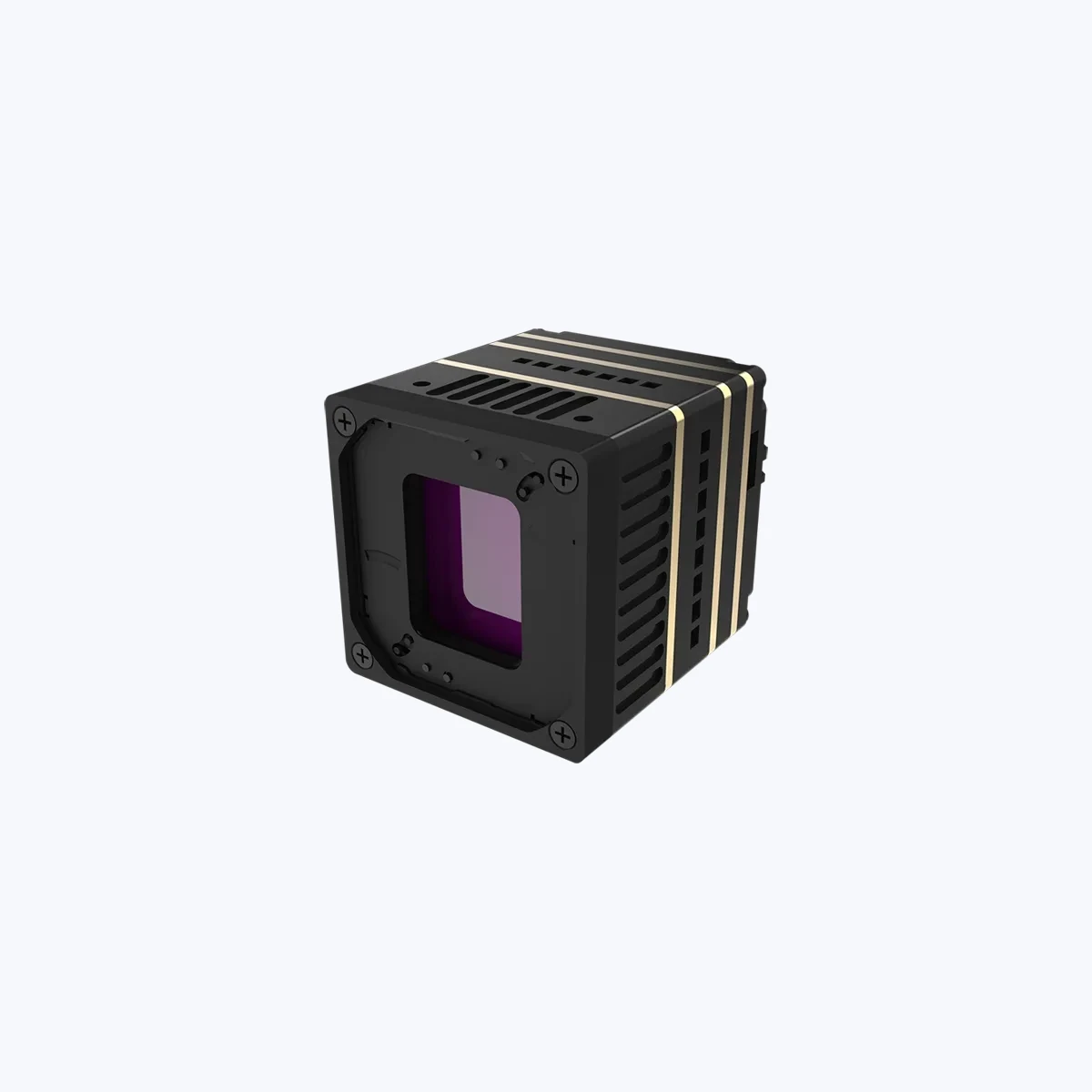
MD-64CA 640×512 Uncooled VOx Thermal Imaging Camera Module
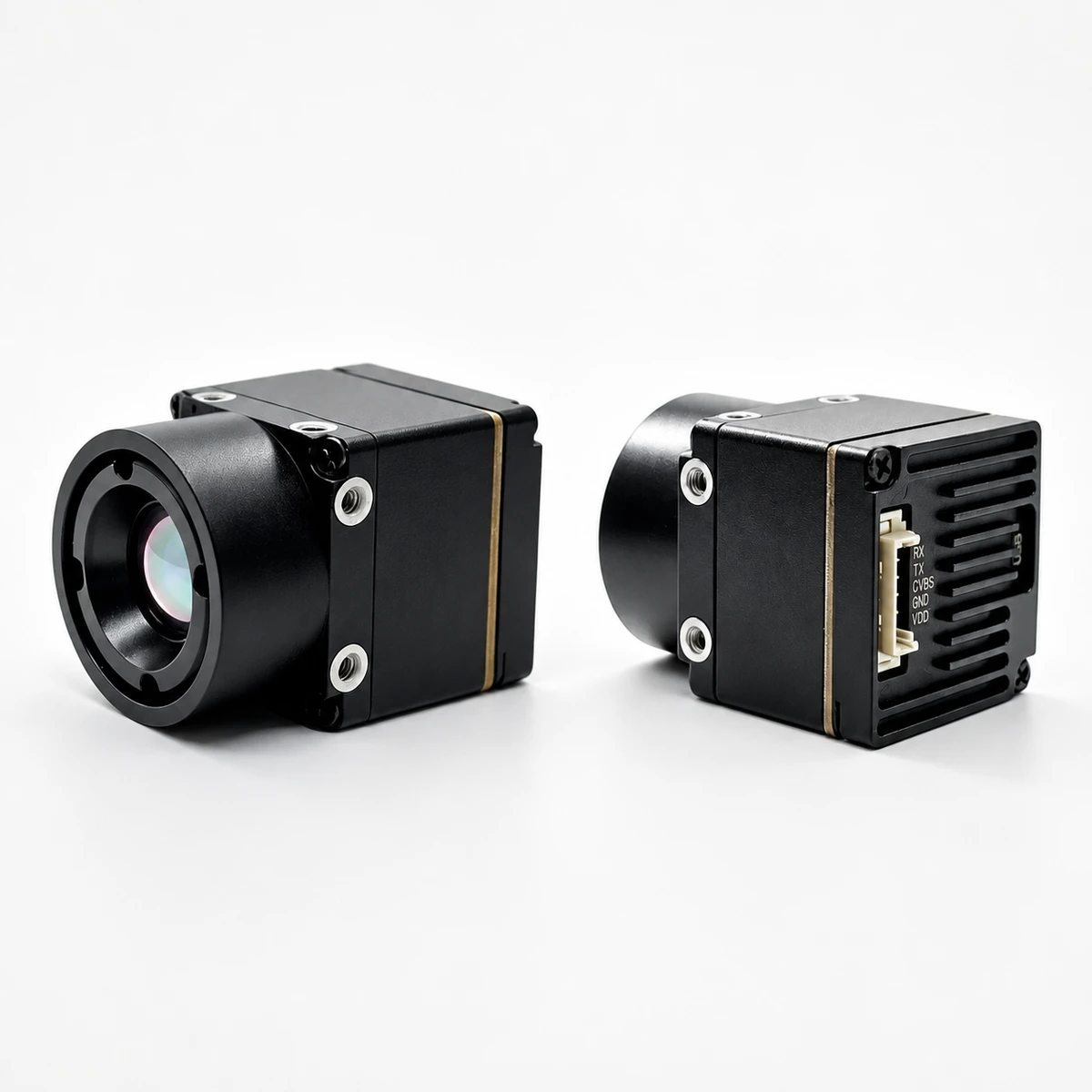
The MD-64CA is a compact, lightweight uncooled thermal camera core engineered for high-volume OEM integration. Built around a 12 µm pixel pitch Vanadium Oxide (VOx) focal plane array operating in the 8–14 µm LWIR band, the MD-64CA delivers 640×512 thermal resolution at a smooth 50 Hz frame rate. Weighing just 23.1 g (without primary lens) and consuming less than 0.7 W of power under active imaging, it fits comfortably into tight SWaP envelopes across robotic payloads, handheld diagnostic tools, and perimeter surveillance systems.
Comprehensive Technical Specifications: MD-64CA
| Parameter | Specification Value / Rating |
|---|---|
| Detector Type | Uncooled Vanadium Oxide (VOx) Focal Plane Array |
| Array Format / Resolution | 640 × 512 pixels |
| Pixel Pitch | 12 µm |
| Spectral Range | 8.0 to 14.0 µm (LWIR) |
| Thermal Sensitivity (NETD) | ≤ 30 mK (@ F1.0, 25°C) |
| Output Frame Rate | 50 Hz (Smooth Real-Time) |
| Supported Output Interfaces | CVBS Analog (PAL/NTSC), USB UVC Digital, or MIPI |
| Interface Pinouts Reference | UVC: USB-VDD, D-, D+, GND | CVBS: Rx, Tx, CVBS, GND, VCC |
| Optical Aperture Rating | F1.0 Maximum Transmission Aperture |
| Operating Voltage Range | 5.0 V to 24.0 V DC (Wide-Voltage Input Tolerance) |
| Power Consumption | < 0.7 W Active Reference Consumption |
| Image Processing Engine | Automatic Non-Uniformity Correction (NUC), < 20 ms Latency |
| Operating Temperature Range | -20°C to +60°C Industrial Rating |
| Core Module Mass | 23.1 g (Excluding primary optics) |
Factory-Fitted Lens Configuration Options: MD-64CA
| Focal Length | Field of View (H × V) | IFOV | Human Det. | Human Rec. | Human Id. |
|---|---|---|---|---|---|
| 4.1 mm | Extra-Wide-Angle Lens (Specifications confirmed with quotation) | ||||
| 4.9 mm | 76.2° × 64.2° | 2.45 mrad | 476.0 m | 119.0 m | 60.0 m |
| 9.1 mm (Standard) | 45.8° × 37.3° | 1.31 mrad | 884.7 m | 221.2 m | 110.6 m |
| 13.0 mm | 33.0° × 26.6° | 0.92 mrad | 1,263.9 m | 316.0 m | 158.0 m |
| 19.0 mm | 22.9° × 18.4° | 0.63 mrad | 1,847.2 m | 461.8 m | 230.9 m |
| 35.0 mm | 12.5° × 10.0° | 0.34 mrad | 3,402.8 m | 850.7 m | 425.4 m |
TM02-SOLO T 6 TOPS Dual-Spectrum UAV AI Tracking Module
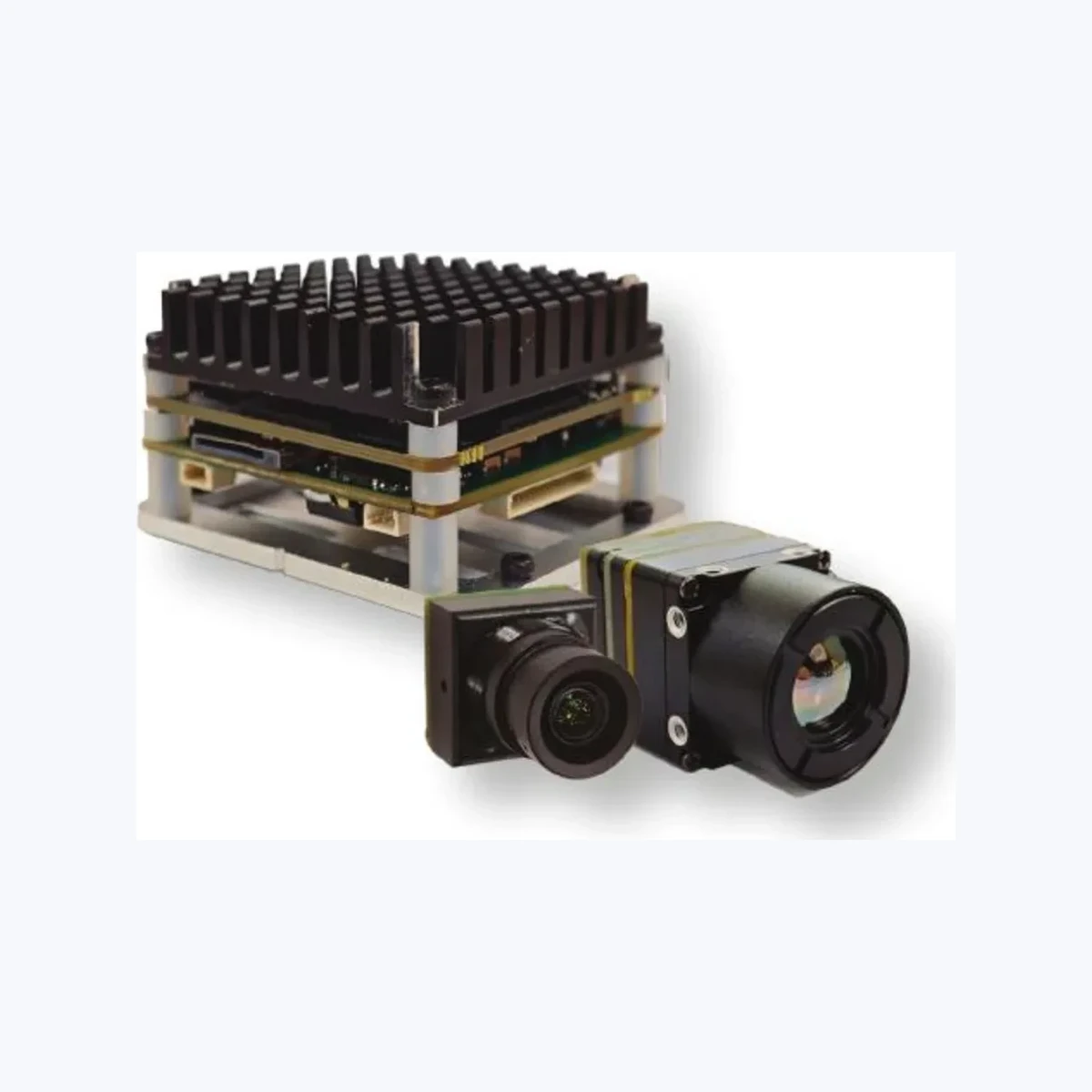
The TM02-SOLO T combines an onboard 6 TOPS neural processing engine with a high-speed 1080p visible sensor and a 640×512 uncooled VOx thermal camera. Designed for UAV OEMs, robotic vision integrators, and surveillance platforms, it handles simultaneous multi-spectral target detection and tracking across daylight, low-light, and zero-lux thermal conditions. Processing runs entirely on the local carrier board, eliminating the latency and bandwidth bottlenecks of offboard video transmission.
Comprehensive Technical Specifications: TM02-SOLO T
| Subsystem | Technical Parameter | Detailed Specification |
|---|---|---|
| Edge AI & Tracking | Compute Architecture | 6 TOPS Dedicated NPU | Arm Cortex-A76 (2.4 GHz) + Cortex-A55 (1.8 GHz) |
| Target Tracking Modes | Reticle locking, close-to-lock, route pre-map, lost-target recall, and PIP fusion | |
| Track Capacity & Limits | Up to 120 simultaneous tracks; minimum target size 10 × 10 pixels | |
| Dynamic Performance | 8 ms processing latency reference; dynamic target speeds up to 450 km/h | |
| Thermal Subsystem | Detector & Resolution | Uncooled VOx microbolometer | 640 × 512 pixels @ 50 Hz |
| Pixel Pitch & Band | 12 µm pixel pitch | 8 to 14 µm (LWIR) | |
| Thermal Lens & FOV | 9.1 mm focal length | Diagonal 61.8°, Horizontal 47.7°, Vertical 38.2° | |
| Visible (EO) Subsystem | Sensor & Sensitivity | 1/1.8-inch CMOS sensor | 0.001 lux low-light reference sensitivity |
| Resolution & Refresh | 1920 × 1080 (1080p) @ 120 Hz high-speed frame rate | |
| Visible Lens & FOV | 8.45 mm focal length | Diagonal 66.3°, Horizontal 57.1°, Vertical 30.4° | |
| System & Electrical | Flight Control Integration | CRSF protocol support | BetaFlight and ArduPilot compatible |
| Power Requirements | Regulated 9.0 V to 16.0 V DC input | |
| Physical Dimensions | Mainboard: 45 × 45 × 26 mm (42.5 × 42.5 mm mount) | EO: 25.5 × 19.5 × 19.5 mm |
For more options across specialized imaging payloads, browse the complete CamCuda OEM Product Catalog.
6. Optics Selection, Germanium Alternatives, and Johnson’s Criteria Calculations
Optical selection for long-wave infrared cameras involves different material trade-offs than visible systems. Standard optical glass (such as N-BK7 or fused silica) absorbs LWIR radiation, rendering standard glass lenses completely opaque between 8 µm and 14 µm.
Optical Substrate Selection for Cost-Effective LWIR Lenses
- ⚙️ Monocrystalline Germanium (Ge): Germanium offers a high refractive index ($n \approx 4.002$ at $10.6\,\mu\text{m}$) and low optical dispersion, allowing lens designers to build compact, low-aberration single- or dual-element lenses. However, raw Germanium is expensive and subject to thermal runaway—its internal absorption rises sharply at temperatures above $60^\circ\text{C}$, degrading optical transmission.
- ⚙️ Chalcogenide Glass (e.g., $\text{Ge}_{28}\text{Sb}_{12}\text{Se}_{60}$): Chalcogenide materials can be precision glass-molded rather than diamond-turned, lowering unit production costs at high volumes. They also feature a lower thermal coefficient of refractive index ($dn/dT$), which helps maintain focus across fluctuating environmental temperatures.
- ⚙️ Precision Silicon (Si): While Silicon provides high transmission in the SWIR and MWIR bands, it exhibits higher absorption in the 8–14 µm LWIR band. It is occasionally used for thin protective windows or specialized narrowband filters, but rarely for primary multi-element LWIR lenses.
Instantaneous Field of View (IFOV) and Spatial Resolution
The Instantaneous Field of View (IFOV) defines the angular footprint covered by an individual pixel. It is determined by the detector’s pixel pitch ($p$) and the lens focal length ($f$):
$$\text{IFOV} = \frac{p}{f} \quad (\text{radians})$$
$$\text{Spatial Resolution at Distance } R = \text{IFOV} \times R$$
For example, pairing the MD-64CA ($p = 12\,\mu\text{m}$) with its standard $9.1\text{ mm}$ focal length lens yields an IFOV of:
$$\text{IFOV} = \frac{12 \times 10^{-6}\text{ m}}{9.1 \times 10^{-3}\text{ m}} = 1.318\text{ mrad}$$
At a distance of $100\text{ meters}$, a single pixel covers an area of approximately $13.18\text{ cm} \times 13.18\text{ cm}$ on the target.
Understanding Target Range with Johnson’s Criteria
Johnson’s Criteria defines the number of resolvable pixel line pairs required across a target’s critical dimension to achieve three primary operational levels:
- Detection (1.5 line pairs / ~3 pixels): An operator or computer-vision algorithm can distinguish that an object is present in the scene.
- Recognition (6.0 line pairs / ~12 pixels): The system can identify the target’s general class (e.g., distinguishing a person from a vehicle).
- Identification (12.0 line pairs / ~24 pixels): The system can discern specific target features (e.g., identifying vehicle types or verifying carried equipment).
When selecting optics, balance the required field of view against your operational range needs. Wider lenses (such as 4.9 mm or 9.1 mm) maximize situational awareness for close-range navigation, while longer focal lengths (such as 19 mm or 35 mm) narrow the FOV to maximize target range.
For long-range surveillance requiring integrated active laser telemetry, consider our high-precision payload platforms, such as the ERA-X Series Long-Range Visible Light Rangefinder Observation Device.
7. OEM Integration Blueprint: Power Conditioning, Thermal Dissipation, and NUC Control
Successfully integrating an inexpensive OEM thermal core requires careful attention to three key hardware design factors: clean power supply design, thermal stabilization, and proper Non-Uniformity Correction (NUC) handling.
1. Electrical Power Design and Ripple Filtering
Uncooled microbolometer readout integrated circuits (ROICs) measure tiny microvolt-level resistance changes. High-frequency electrical noise or voltage ripple on the power input directly degrades thermal sensitivity, appearing as horizontal lines, rolling bands, or checkerboard noise across the thermal video feed:
- ⚙️ Supply Regulation: Power the module using low-dropout (LDO) linear regulators or isolated DC-DC stages with ripple levels below $15\text{ mV}_\text{p-p}$.
- ⚙️ Filtering & Decoupling: Place high-frequency ceramic decoupling capacitors ($0.1\,\mu\text{F}$ in parallel with $10\,\mu\text{F}$ low-ESR ceramic caps) directly adjacent to the module’s power input pins.
- ⚙️ Ground Isolation: Isolate high-current motor grounds (such as drone ESCs, pan-tilt gimbal servos, or robotic drive wheels) from the sensor’s analog and digital ground planes to prevent ground bounce.
2. Thermal Path and Structural Heat Sinking
While uncooled VOx microbolometers consume relatively little power (<0.7 W for the MD-64CA), the sensor die is sensitive to internal temperature gradients. Uneven heat buildup from nearby computing boards, motor drivers, or power converters can cause spatial calibration drift across the focal plane:
- ⚙️ Mount the thermal module’s metal chassis to an aluminum frame or housing using a high-performance thermal interface material (TIM) with a conductivity rating of at least $3.0\text{ W/m}\cdot\text{K}$.
- ⚙️ Keep transient thermal drift rates below $0.5^\circ\text{C}/\text{min}$. Rapid temperature spikes force the core to trigger frequent NUC recalibrations, temporarily interrupting the video stream.
- ⚙️ Ensure cooling airflow across the host enclosure is distributed evenly, avoiding direct, localized hot spots on one side of the thermal core casing.
3. Shutter-Based vs. Shutterless Non-Uniformity Correction (NUC)
Microbolometer pixels naturally drift over operational time and ambient temperature variations. Non-Uniformity Correction resets the offset values across all pixels to maintain a clean, flat thermal baseline:
- ⚙️ Electromechanical Shutter NUC: An internal solenoid briefly moves a uniform, emissivity-controlled shutter blade in front of the FPA for 200–400 ms, allowing the ISP to recalculate pixel offset tables. Ensure your mechanical mount allows enough clearance for the shutter mechanism to actuate without binding.
- ⚙️ Scene-Based Shutterless Algorithms: For dynamic applications where even a momentary 200 ms frame-freeze is unacceptable, advanced ISP firmware can dynamically update pixel offsets by analyzing continuous target motion across the scene. Note that shutterless modes require ongoing scene movement; static cameras viewing a stationary background can develop thermal ghosting over time.
8. Deep-Dive Engineering FAQ
What is the practical difference between an inexpensive NIR night vision camera and a true uncooled LWIR thermal core?
In contrast, an uncooled LWIR core (such as the 640×512 VOx MD-64CA) operates in total darkness ($0.000\text{ lux}$) without any active illuminators. LWIR systems easily cut through environmental obscurants, cannot be blinded by vehicle headlights or bright spotlights, and provide temperature contrast data that enables automated edge-AI detection algorithms to reliably classify human and vehicular targets.
Why are full-framerate (50 Hz) thermal cameras preferred over inexpensive 9 Hz modules for robotics and drones?
Full-framerate 50 Hz modules (such as the TM02-SOLO T tracking payload and MD-64CA core) refresh every 20 milliseconds. This 5× improvement in temporal resolution eliminates motion smear, provides smooth video for remote operators, and delivers steady, real-time bounding-box telemetry. This level of responsiveness is essential for fast optical tracking, automated landing, obstacle avoidance, and dynamic gimbal stabilization.
Can inexpensive thermal imaging camera modules be used for absolute radiometric temperature measurement?
True radiometric measurement requires factory-calibrated look-up tables (LUTs), an internal shutter reference point, real-time lens temperature compensation, and user adjustments for target emissivity and atmospheric transmission. If your application specifically requires calibrated surface temperature measurement (e.g., electrical substation predictive maintenance or automated medical fever screening), you should confirm radiometric calibration requirements with the manufacturer before freezing your system specifications.
How do I select the right optical focal length for an uncooled 640×512, 12 µm thermal module?
• Wide-Angle Lenses (4.1 mm to 4.9 mm, ~76° H-FOV): Best suited for close-range situational awareness, indoor robotic navigation, wide-area perimeter monitoring, and broad search operations where human detection is needed within 450 meters.
• Standard Field Lenses (9.1 mm to 13 mm, 45° to 33° H-FOV): Provide a balanced profile for small UAV gimbals and autonomous mobile robots (AMRs), enabling human detection out to 880–1,260 meters while retaining enough horizontal coverage for general situational awareness.
• Telephoto Lenses (19 mm to 35 mm, 22° down to 12.5° H-FOV): Ideal for long-range inspection, border monitoring, and high-altitude UAV search-and-rescue payloads, extending human detection ranges to 1,800–3,400 meters at the expense of a narrower field of view.
📚 References & Further Reading
- Industry Standard: Learn more about high-speed digital machine vision transmission via the A3 USB3 Vision Standard Guidelines.
- Theoretical Foundation: Review fundamental concepts in neural processing and automated image analysis on Wikipedia’s Artificial Intelligence Overview.
- Related Payload Guide: Explore practical payload design strategies in our tutorial on how to choose a 640×512 thermal camera module for drone payloads.
- Long-Range Vision Systems: Compare integrated multi-sensor laser tracking hardware using the ERA-X Series Long-Range Visible Light Rangefinder Module.