Cheap Infrared Camera vs. OEM Thermal Core: B2B Integration Guide
Cheap Infrared Camera vs. OEM Thermal Core: B2B Integration Guide
Technical author: Daniel · Hardware Support
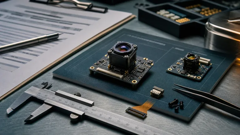
Engineering teams building uncrewed aerial vehicles (UAVs), ruggedized ground robotics, and perimeter security and observation platforms often face a build-versus-buy decision. A search for a cheap infrared camera can return near-infrared security boards, smartphone thermal accessories, and embedded thermal modules. Their prices may look comparable before the team checks the sensing band, host access, mechanical packaging, and software requirements. Those differences can determine how much integration work the project needs.
A consumer camera can be useful for an early feasibility test. For a production system, compare the complete integration cost: camera, optics, host processing, cables, mounting, environmental testing, software maintenance, and supplier documentation. This guide explains the consumer-versus-OEM trade-offs, then compares two current dual-spectrum AI configurations: CAMCUDA AI VisionCube DT Pro and ST Pro. It separates published component specifications from performance that still needs to be measured on your own platform.
Table of Contents
- 👉 1. Physics & Spectrum: Near-Infrared (NIR) vs. Long-Wave Infrared (LWIR)
- 👉 2. The Engineering Traps of Budget Thermal Cameras
- 👉 3. Architectural Comparison: Consumer Gadgets vs. Industrial OEM Cores
- 👉 4. Dual-Spectrum OEM Modules: Current VisionCube Specifications
- 👉 5. SWaP-C Optimization: Balancing Compute, Optics, and Sensor Pitch
- 👉 6. Host & Flight-Controller Integration: Interfaces and Validation
- 👉 7. Step-by-Step B2B Procurement and Flight Validation Checklist
- 👉 8. Frequently Asked Questions (FAQ)
1. Physics & Spectrum: Near-Infrared (NIR) vs. Long-Wave Infrared (LWIR)
Start by identifying what “infrared” means in the listing. Near-infrared night vision and long-wave thermal imaging use different parts of the spectrum. A low price alone does not tell you which sensing method you are buying, and a consumer thermal camera can contain a genuine LWIR detector.
Many inexpensive night-vision boards use silicon CMOS sensors with an absent or switchable IR-cut filter. They can detect reflected near-infrared illumination, commonly supplied by 850 nm or 940 nm LEDs. Performance depends on illumination, reflectance, exposure, and distance. This type of camera does not measure the thermal emission used by an LWIR imager.
LWIR imaging can reveal thermal contrast without a visible-light illuminator. It still needs a usable line of sight and enough contrast between the object and its surroundings. Fog, rain, smoke, dust, windows, and protective covers can affect the two camera channels differently. Avoid an all-weather or “see-through” guarantee; test the actual environment and enclosure window. FLIR explains how fog and rain can limit thermal imaging range.
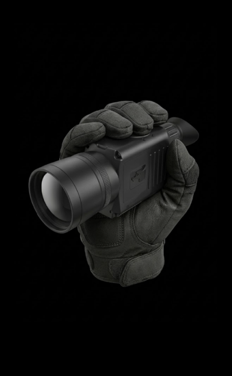
Thermal radiation emitted by an object depends on its temperature and emissivity. A thermal camera receives radiation within its spectral band, together with reflected background radiation and the effects of the optical path. A contrast image therefore does not by itself establish an accurate surface temperature. Quantitative temperature measurement requires a documented radiometric calibration and suitable measurement conditions.
| Optical Band | Illustrative Wavelength Range | Common Detector Technology | Imaging Principle |
|---|---|---|---|
| Visible light | Approximately 0.38–0.75 μm | Silicon CMOS / CCD | Primarily reflected ambient or artificial light |
| Near-infrared (NIR) | Approximately 0.75–1.0 μm for the silicon night-vision examples discussed here | Silicon CMOS | Reflected ambient or active NIR illumination |
| Short-wave IR (SWIR) | Approximately 1.0–2.5 μm; detector coverage varies | InGaAs and other detector options | Often reflected illumination; response depends on the detector |
| Mid-wave IR (MWIR) | Common imaging window: 3–5 μm | Often cooled InSb or MCT | Thermal emission and reflected radiation |
| Long-wave IR (LWIR) | Common imaging window: 8–14 μm | Uncooled VOx / a-Si microbolometers, among other options | Thermal emission and reflected radiation |
An uncooled microbolometer converts absorbed radiation into a small change in detector temperature and electrical response. Readout electronics turn that response into an image. Detector material, readout design, optics, and correction processing all matter, but generic microbolometer descriptions are not a substitute for the bill of materials of a selected camera.
For a wider sourcing overview, see the infrared camera module OEM buying guide. Use both guides to frame questions for the supplier, then verify the current configuration documents before committing a design.
2. The Engineering Traps of Budget Thermal Cameras
The main risk when adapting a cheap infrared camera to a robot or UAV is discovering an integration limit after the mechanical and software design is fixed. A mobile accessory may depend on a particular application, operating system, connector, or licensing arrangement. An OEM label also needs scrutiny: it does not automatically establish low latency, environmental qualification, or host compatibility.
| Technical Metric | Consumer Camera: What to Check | VisionCube DT Pro / ST Pro: Published Reference and Validation |
|---|---|---|
| Frame rate | Read the exact model specification and test the delivered stream; consumer rates vary | Thermal: 640 × 512 at 50 Hz; visible: 1920 × 1080 at 30 Hz for both configurations |
| End-to-end latency | Measure capture, transfer, buffering, and application processing | No measured end-to-end latency established here; test the selected configuration and host |
| Host and control interface | Confirm supported hosts, drivers, software access, and connector retention | Thermal-camera USB is listed; request the selected VisionCube AI-interface and video/control documents |
| Environmental behavior | Verify the documented operating limits and behavior in the intended enclosure | Obtain configuration-specific limits; characterize temperature drift, cooling, vibration, and EMI |
| AI processing | Check whether processing is on the camera, phone, or external host | DT Pro: 6 TOPS; ST Pro: 1 TOPS. Validate the supported workload separately |
| Flight-controller integration | Confirm available data access and any required host software | Validate commands, outputs, and host bridging; native autopilot protocol compatibility is not established by these specifications |
Some consumer thermal products operate at about 9 Hz, but that is not a universal consumer specification or a complete statement of export law. For a device updating at 9 Hz, the interval is about 111 ms. A platform moving at 25 m/s travels about 2.78 m during that interval. This example describes sampling distance, not a guaranteed tracking failure: image motion also depends on viewing geometry, stabilization, exposure, and the tracking algorithm.
A 50 Hz thermal stream has a nominal 20 ms frame interval; a 30 Hz visible stream has a nominal 33.3 ms interval. Neither number is an inference latency or command-response measurement. Capture timing, synchronization, encoding, transport, buffering, and host processing all contribute to the usable result. Specify an end-to-end test and record both typical delay and variation under the intended workload.
USB and UVC can be suitable for embedded designs when the camera, host, drivers, and application are supported. Do not assign a fixed latency penalty to the connector type. Test restart behavior, dropped frames, timestamp access, sustained bandwidth, cable retention, and software licensing before choosing an architecture.
Non-uniformity correction (NUC) and temperature compensation also deserve a bench test. Ask how the chosen module performs corrections, whether image interruptions occur, and how the host identifies stale frames. Check warm-up, temperature changes, and enclosure heating rather than assuming that either a consumer or OEM product will be free of drift.
Export, import, end-use, and local UAV requirements depend on the product and transaction. Ask the supplier for the applicable classification and supporting documents, and obtain qualified compliance advice where needed. Frame rate alone is not sufficient to establish whether an order can be shipped or used in a particular jurisdiction.
3. Architectural Comparison: Consumer Gadgets vs. Industrial OEM Cores
For industrial inspection and observation applications, compare architectures by where images are acquired, processed, and delivered. A consumer camera may be quick to demonstrate, while a standalone OEM thermal core can give an integrator more control over the host pipeline. A dual-spectrum AI module adds visible imaging and onboard processing, with its own software and integration requirements.
In a host-centric design, the external computer may need to receive thermal images, handle image processing, align a separate visible camera, and run application logic. That can be appropriate when the team already has a capable host and needs access to its own processing stack. Budget for synchronization, bandwidth, compute loading, thermal management, and long-term driver support rather than assuming that every consumer accessory exposes the same data.
The VisionCube family offers a different starting point. DT Pro combines dual visible cameras with a thermal camera and 6 TOPS processing; ST Pro combines a single visible camera with a thermal camera and 1 TOPS processing. Both Pro configurations publish 640 × 512 thermal output at 50 Hz and 1920 × 1080 visible output at 30 Hz. These are two configurations of the same current product family, with different visible-camera arrangements and processing capacity.
Picture-in-picture is listed in the supplied brochure. It should be evaluated separately from synchronized capture, geometric registration, fused imagery, or AI inference throughput. Ask which video modes, AI commands, and result outputs the selected firmware provides, and how a host can use them. A TOPS figure describes processing capacity; it does not establish object classes, simultaneous tracks, detection distance, or autopilot behavior.
Optical packaging also needs its own review. Ordinary visible-light windows are generally unsuitable for LWIR transmission, so an enclosure must accommodate the thermal optical path. Lens material, coatings, aperture, focus, and environmental durability are configuration-specific. Confirm those details rather than assuming that every industrial core has a germanium lens, a particular protective coating, or the same outdoor qualification.
4. Dual-Spectrum OEM Modules: Current VisionCube Specifications
The two showcases below retain the dual-spectrum comparison while using current AI VisionCube specifications. The product family lists six configurations; DT Pro and ST Pro are the 640 × 512 thermal options considered here. The tables use the supplied brochure dated March 4, 2026, as presented on the current product page. Confirm the selected hardware revision, accessories, software, and integration documents with the supplier.
Product Model: CAMCUDA AI VisionCube DT Pro
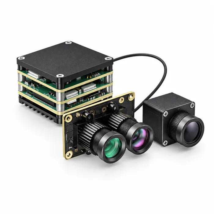
AI VisionCube DT Pro combines wide-angle and telephoto visible imaging with a 640 × 512 thermal camera and 6 TOPS processing. Its visible optics are 3.9 mm wide-angle and 12 mm telephoto, with published fields of view of 72° H × 45° V and 26° H × 15° V. This configuration is worth evaluating when a civilian inspection or observation project needs both visible views alongside thermal imagery. Verify the available view selection, output modes, and AI behavior on the sample.
| AI VisionCube DT Pro Published Configuration Specifications | |
|---|---|
| AI Processing & Integration | |
| AI processing | 6 TOPS |
| Integration documentation | Request AI VisionCube DT Pro AI-interface, video/control, and software integration documents for the selected hardware and firmware |
| Picture-in-picture | Supported according to the supplied brochure; validate modes and output behavior on the selected configuration |
| AI acceptance testing | Confirm supported commands, outputs, and workloads; processing capacity does not establish detection range, inference rate, or end-to-end latency |
| Thermal Camera (LWIR) Component | |
| Resolution & frame rate | 640 × 512 at 50 Hz |
| Spectral band & pixel pitch | 8–14 μm LWIR; 12 μm pixel pitch |
| Lens & field of view | 9.1 mm; 45.9° H × 36.9° V |
| Thermal-camera interface | USB, as listed in the brochure; confirm the complete kit video/control connections |
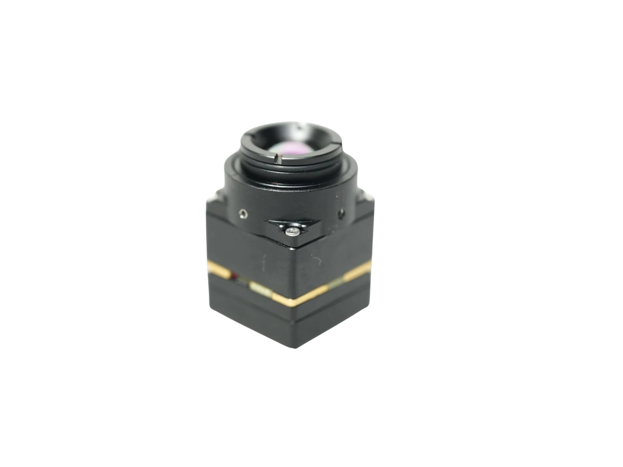
| Thermal-camera dimensions | 26 × 26 × 21.1 mm, excluding lens and connectors |
| Thermal-camera weight | ≤23 g, excluding lens and connectors |
| Radiometric temperature measurement | Calibrated temperature-measurement range and accuracy are not established by the supplied specifications |
| Visible Camera Component | |
| Visible configuration | Dual visible: wide-angle + telephoto |
| Visible output | 1920 × 1080 at 30 Hz |
| Visible optics | 3.9 mm wide-angle + 12 mm telephoto |
| Visible field of view | Wide-angle: 72° H × 45° V; telephoto: 26° H × 15° V |
| Visible-camera dimensions | 40.8 × 25 × 26 mm; component reference |
| Common Processing-Board Reference | |
| Board input | 9–16 V; verify the selected kit power connection, polarity, and current requirements |
| Board dimensions | 38 × 38 × 29 mm |
| Mounting pattern | 25.5 × 25.5 mm |
| Board weight | 43.8 g |
| Complete assembly | Board and camera figures above are component specifications. Obtain the full kit drawing, assembled mass, cable clearances, and included accessories |
The brochure contains differing CMOS-size entries in its visible-camera subsections. Confirm the final DT Pro camera bill of materials rather than carrying a single sensor-size claim into a procurement drawing. The published sensitivity units are not a minimum-illumination lux rating. No CPU model, guaranteed detection range, target speed, simultaneous-track count, or measured end-to-end latency is established in this guide.
View VisionCube and Select DT Pro ➔
Product Model: CAMCUDA AI VisionCube ST Pro
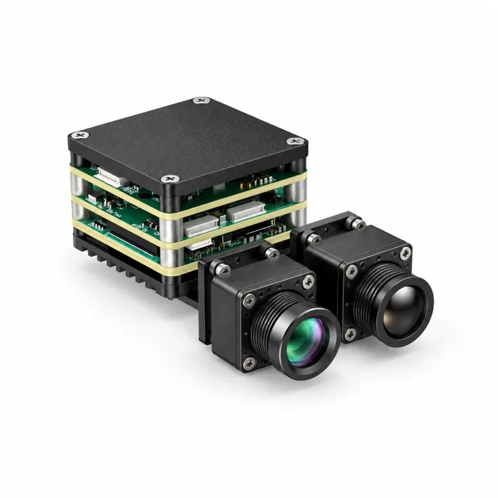
AI VisionCube ST Pro combines one visible camera with a 640 × 512 thermal camera and 1 TOPS processing. Its 4 mm visible lens provides a published 69° H × 42° V field of view. It is a candidate for projects that need one visible view alongside thermal imagery and can validate their required workload on the 1 TOPS configuration. Its thermal resolution, thermal frame rate, and 9.1 mm thermal optics match the published Pro thermal specification used above.
| AI VisionCube ST Pro Published Configuration Specifications | |
|---|---|
| AI Processing & Integration | |
| AI processing | 1 TOPS |
| Integration documentation | Request AI VisionCube ST Pro AI-interface, video/control, and software integration documents for the selected hardware and firmware |
| Picture-in-picture | Supported according to the supplied brochure; validate modes and output behavior on the selected configuration |
| AI acceptance testing | Confirm supported commands, outputs, and workloads; processing capacity does not establish detection range, inference rate, or end-to-end latency |
| Thermal Camera (LWIR) Component | |
| Resolution & frame rate | 640 × 512 at 50 Hz |
| Spectral band & pixel pitch | 8–14 μm LWIR; 12 μm pixel pitch |
| Lens & field of view | 9.1 mm; 45.9° H × 36.9° V |
| Thermal-camera interface | USB, as listed in the brochure; confirm the complete kit video/control connections |
| Thermal-camera dimensions | 26 × 26 × 21.1 mm, excluding lens and connectors |
| Thermal-camera weight | ≤23 g, excluding lens and connectors |
| Radiometric temperature measurement | Calibrated temperature-measurement range and accuracy are not established by the supplied specifications |
| Visible Camera Component | |
| Visible configuration | Single visible |
| Visible output | 1920 × 1080 at 30 Hz |
| Visible optics | 4 mm |
| Visible field of view | 69° H × 42° V |
| Visible-camera dimensions | 19 × 19 × 30 mm; component reference |
| Common Processing-Board Reference | |
| Board input | 9–16 V; verify the selected kit power connection, polarity, and current requirements |
| Board dimensions | 38 × 38 × 29 mm |
| Mounting pattern | 25.5 × 25.5 mm |
| Board weight | 43.8 g |
| Complete assembly | Board and camera figures above are component specifications. Obtain the full kit drawing, assembled mass, cable clearances, and included accessories |
Both tables distinguish the processing board from the visible-camera and thermal-camera components. Do not treat the 43.8 g board weight as complete payload mass, or sum the listed dimensions into a kit envelope. Lens, connectors, mounts, cables, cooling, and other included parts need an assembly-level drawing and measured mass.
View VisionCube and Select ST Pro ➔
For either model, select the exact configuration on the VisionCube product page and use its configuration-review request path to obtain the current AI-interface, video/control, software, and mechanical documents. If you contact CAMCUDA sales support, state “AI VisionCube DT Pro” or “AI VisionCube ST Pro” in the request. Documents for an unrelated standalone thermal core do not establish the VisionCube connector definitions or host compatibility.
Supplier demonstration footage can help explain the displayed views, but its on-screen distances, speeds, and tracking annotations do not establish acceptance criteria for either configuration. Set your own civilian inspection or observation tests. For broader background, browse the embedded vision technical knowledge base.
5. SWaP-C Optimization: Balancing Compute, Optics, and Sensor Pitch
SWaP-C planning balances size, weight, power, and cost; cooling is part of that system design. Compare the full payload rather than only a camera board. Include optics, protective windows, brackets, cables, power conversion, heat spreading, host processing, and the software work needed to deliver usable images.
Pixel pitch and focal length provide a useful first estimate of angular sampling. With both quantities expressed in the same units, the small-angle approximation for one detector pixel is:
IFOV ≈ Pixel Pitch (p) / Focal Length (f), in radians
For the published 12 μm pitch and 9.1 mm thermal lens of DT Pro and ST Pro, this estimate is about 1.32 mrad per pixel. It is a sampling estimate, not a detection or identification range. Contrast, focus, motion blur, atmospheric transmission, optics, processing, and the required number of pixels across an object still affect useful performance. Use the thermal imaging calculator for preliminary geometry, then compare it with the specified lens and real imagery.
At the same angular sampling, a smaller pixel pitch can permit a shorter focal length. Whether that reduces lens mass or cost depends on aperture, image circle, lens design, material, coating, tolerances, and production volume. Pixel pitch alone does not guarantee lower total cost, equal detection range, or longer flight time.
Compare the visible channels separately. DT Pro provides wide-angle and telephoto views; ST Pro provides a single visible view. Their visible fields of view differ from the shared thermal field of view, so evaluate boresight alignment, overlap, working distance, and picture-in-picture presentation. A useful thermal feature may occupy a different part of a visible image, especially at short distances.
Onboard AI processing can change how much work the host must perform, but software cannot recover optical detail that was never captured. It also does not automatically replace a gimbal, optical zoom, stabilization, or cooling. Measure power and temperature under the supported workload, and choose mechanical stabilization from the platform requirements rather than a TOPS comparison.
6. Host & Flight-Controller Integration: Interfaces and Validation
Treat power, video transport, AI control/results, and vehicle telemetry as separate integration requirements. Start with the selected DT Pro or ST Pro hardware and firmware documents. Confirm the supported host, connector definitions, signal levels, software versions, and available commands before designing a carrier or connecting a flight controller.
The common processing-board reference lists 9–16 V input. This does not define every camera connector or establish complete kit power consumption. Ask for the approved power-entry point, polarity, current requirements, startup behavior, and grounding guidance. Design supply filtering and protection from those requirements, then test the assembled payload for ripple, transients, thermal behavior, and interference with other electronics.
For AI integration, request the model-specific interface specification, command and output definitions, supported software tools, and any sample host code. Confirm how video and AI results are identified, timed, and associated, as well as what happens during startup, correction cycles, connection loss, and recovery. The existence of AI interfaces does not establish a particular vehicle protocol implementation.
- Video path: Confirm the supported output modes, formats, rate, transport, and host software. The brochure’s thermal-camera USB entry is not a complete wiring specification for the assembled AI kit
- AI command and result path: Verify the selected firmware’s commands, result fields, timing, and operating modes. Implement and test only the documented functions
- Vehicle or gimbal interface: Check whether a host-side bridge is needed. ArduPilot, BetaFlight, CRSF, or another control stack requires a separately validated integration; do not assume native support from the camera specifications
- Operational safeguards: Keep observation and data logging separate from any actuation until the whole system has passed its own review. Define stale-data handling, fault states, operator override, and safe recovery for the application
Measure end-to-end timing with the intended host and full software pipeline. A nominal camera frame rate does not establish synchronization between sensors or a safe feedback-loop rate. Bench validation should establish restart behavior, error reporting, resource use, and the effect of missing or delayed data before controlled platform trials.
Use the current VisionCube specifications to identify the selected configuration, and request its matching technical package through the product page. There is no verified VisionCube wiring diagram included in this article. Use the supplier’s revision-matched connector drawing instead of adapting a pin diagram from another camera family.
7. Step-by-Step B2B Procurement and Flight Validation Checklist
A useful B2B acceptance plan ties each requirement to a document, a sample test, and an agreed result. Keep the selected configuration and hardware/firmware revisions attached to every record so that a later component change does not silently invalidate the work.
Phase 1: RFQ and Interface Specification Verification
- Configuration and documentation: Name DT Pro or ST Pro, quantity, intended civilian application, host, destination, and schedule. Obtain matching mechanical, connector, power, AI-interface, software, and accessory details
- Optical matching: Use thermal 45.9° H × 36.9° V as the published Pro reference. Check the selected visible field of view separately: DT Pro wide-angle 72° H × 45° V and telephoto 26° H × 15° V; ST Pro 69° H × 42° V
- Acceptance criteria: Agree image-quality, data-access, timing, environmental, and application requirements. If calibrated temperature data is essential, require an explicit range, accuracy, output format, and calibration basis before selecting the product
Phase 2: Bench Integration and EMI Characterization
- Power verification: Check the selected kit’s approved input, startup current, steady-state load, ripple, and transients against its documentation. Do not impose an undocumented generic ripple limit as a product specification
- EMI and resource use: Test the complete payload with its host, radios, navigation receiver, and intended cables. Record interference, host loading, frame loss, and heat buildup
- Data and command validation: Verify the documented video and AI interfaces, timestamps where available, command handling, connection recovery, and any host-side vehicle bridge. Record end-to-end timing under representative load
Phase 3: Thermal Stress and NUC Behavior
- Environmental tests: Use an agreed test profile within documented component and assembly limits. Check warm-up, enclosure temperature, drift, focus, and image consistency
- Correction and interruption behavior: Identify whether and how NUC or shutter events interrupt the stream. Verify that the application detects stale or invalid data and recovers safely
Phase 4: Controlled Platform and Field Validation
- Mechanical validation: Check mounting, vibration, connector retention, strain relief, cooling, and full payload mass. Begin with bench and controlled ground tests before an authorized flight trial
- Application validation: Evaluate the actual inspection or observation scene, distance, weather, platform motion, and occlusion conditions. Record false results and recovery behavior; do not use supplier-demo annotations as guaranteed performance
- Release and compliance: Document unresolved limits, supplier revisions, maintenance needs, and applicable operational and transaction requirements. Engineering tests alone do not constitute flight certification
8. Frequently Asked Questions (FAQ)
What is the primary difference between a cheap infrared camera and an OEM thermal core?
Why do consumer thermal smartphone dongles fail in UAV and robotic tracking applications?
Suitability depends on the exact camera and the integration requirements. Check sustained frame rate, latency, host access, licensing, connector retention, environmental limits, and correction behavior. Some low-rate products may be unsuitable for a moving-platform application, while others can support a feasibility study. VisionCube DT Pro and ST Pro publish 50 Hz thermal and 30 Hz visible output, but their end-to-end latency, AI workload, and host integration still require validation. Native autopilot compatibility should not be inferred from those frame rates.
How does microbolometer pixel pitch affect the overall system bill of materials (BOM)?
Can the thermal channel on dual-spectrum tracking modules be used for radiometric temperature measurement?
The current VisionCube DT Pro and ST Pro specifications do not establish calibrated temperature-measurement range or accuracy. Use their published thermal specifications as imaging information. If the project requires quantitative temperature data, obtain explicit radiometric capability, calibration, output-format, range, and accuracy documentation for the exact product before selecting it. Image contrast or a color palette alone cannot support a precision temperature claim.
References & Further Reading
- Current model specifications: AI VisionCube visible, thermal, and processing-board specifications
- Configuration documents: Select DT Pro or ST Pro on the VisionCube product page and request its matching technical package
- Atmospheric limits: FLIR: thermal imaging in fog and rain
- Related guide: Infrared Camera Module OEM Buying Guide
- Preliminary geometry: Thermal imaging calculator
For configuration and quotation support, contact Vivian, Lena, or Sophie through CAMCUDA sales support. Include DT Pro or ST Pro, intended quantity, host interfaces, imaging requirements, and the documents needed for your integration review.