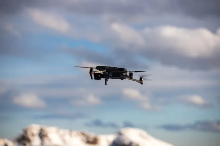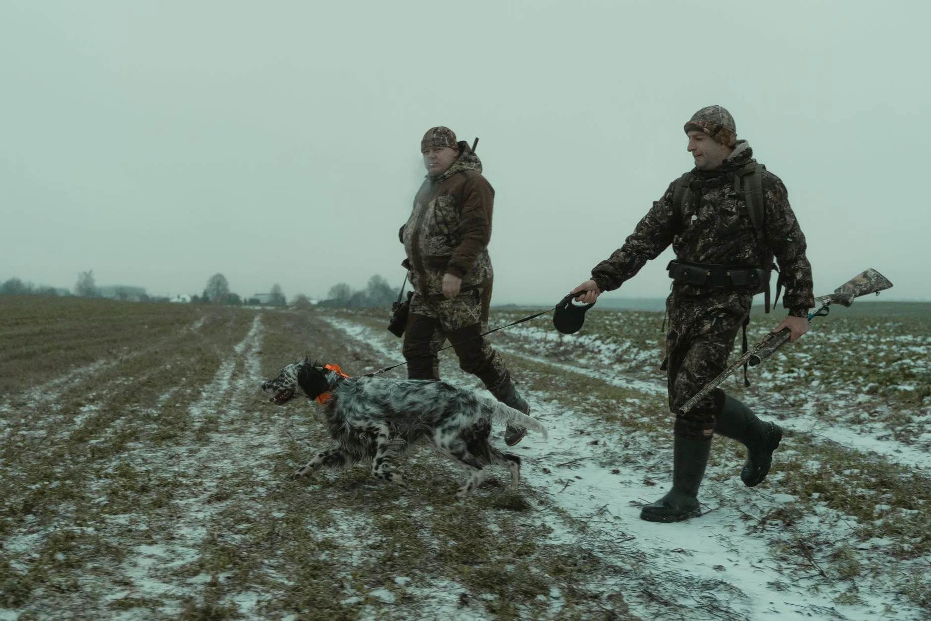
Thermal Drone for Hunting & Game Recovery: OEM Payload Sourcing Guide
The integration of long-wave infrared (LWIR) payloads on unmanned aerial vehicles (UAVs) has fundamentally altered modern wildlife management, invasive species eradication, and commercial game recovery operations. Designing a high-performance thermal drone for hunting, tracking, and recovery applications requires solving complex systems engineering equations: balancing strict Size, Weight, and Power (SWaP) constraints against optical reach, sensor sensitivity, and real-time processing throughput. For aerospace engineers, gimbal integrators, and original equipment manufacturers (OEMs), developing an efficient aerial tracking platform demands deep technical command over thermal core architectures, microbolometer materials science, focal length optics, digital versus analog signal transmission latencies, and biological thermal contrast discrimination under heavy canopy foliage.
Commercial game recovery operations, such as tracking downed white-tailed deer in heavily wooded acreage or locating invasive feral hog sounders in dense brush, require systems capable of isolating low-temperature biological targets from intense environmental thermal clutter. From typical operating altitudes between 50 and 120 meters Above Ground Level (AGL), solar loading on ground objects like rocks, exposed dirt, and fallen logs can create extreme noise. Successfully distinguishing game targets from background clutter hinges directly on the microbolometer’s Noise Equivalent Temperature Difference (NETD), sensor pixel pitch, instantaneous field of view (IFOV), and raw system integration protocols. This technical engineering guide delivers an exhaustive analysis of OEM thermal core selection, optical range modeling via Johnson Criteria benchmarks, communication bus trade-offs, and mechanical integration guidelines for engineers building next-generation aerial tracking and recovery payloads.
Table of Contents
- 👉 1. Thermal Physics & Wildlife Detection Challenges in Airborne LWIR
- 👉 2. SWaP-C Optimization for Aerial Gimbal Payloads
- 👉 3. Optics, IFOV, and the Johnson Criteria for Airborne Game Recovery
- 👉 4. Video Interfaces, Latency, and Processing Pipelines
- 👉 5. Architectural Evaluation: 640×512 vs. 1280×1024 Sensor Architectures
- 👉 6. OEM Sourcing: Technical Product Specifications & Performance Profiles
- 👉 7. Systems Engineering & Integration Checklist
- 👉 8. Deep-Dive Frequently Asked Questions
1. Thermal Physics & Wildlife Detection Challenges in Airborne LWIR
Thermal imaging payloads deployed on aerial platforms detect naturally emitted infrared radiation across the long-wave infrared (LWIR) spectrum, spanning 8 to 14 micrometers (μm). Unlike visible-spectrum cameras (400–700 nm) or near-infrared (NIR) sensors (750–1000 nm) that depend on reflected ambient photon flux, LWIR microbolometers convert target surface radiant emittance directly into electrical signals. This operational physics makes thermal cores indispensable for aerial hunting, invasive species tracking, and game recovery operations conducted in complete darkness or across complex terrains.
Look at the thermal reality of biological targets from the air: it is an unforgiving radiometric environment. An animal’s core internal body temperature sits between 37.5°C and 39.5°C (310.65 K to 312.65 K). But in the field, your airborne sensor never sees that core heat. What it actually detects is the heavily insulated external surface—a boundary layer of winter fur, dense fat, or thick feathers. The effective radiometric delta (ΔT) of an adult white-tailed deer, elk, or feral hog in freezing weather is often razor-thin, hovering between just 0.5°C and 2.0°C above the surrounding soil and brush. Resolving that tiny temperature delta without burying the image in sensor noise requires exceptional focal plane array sensitivity.
Environmental clutter makes this problem significantly harder. During daytime hours, solar radiation bakes high-thermal-mass abiotic objects like exposed granite boulders, dry dirt tracks, fallen oak logs, and stagnant mud puddles. By mid-afternoon, these environmental clutter elements radiate at apparent temperatures that easily exceed biological targets, swamping your detector. Even worse is the phenomenon known as “thermal crossover.” Twice a day—at dawn and dusk—the ground temperature matches the target’s radiant temperature almost perfectly. At that exact crossover point, thermal contrast drops to near zero, causing targets to vanish completely on poorly spec’d sensors.
Here’s how we beat thermal crossover and severe background noise on the engineering side: you maximize the Signal-to-Clutter Ratio (SCR) by driving down the raw microbolometer noise floor. Vanadium Oxide (VOx) thin-film arrays outperform legacy Amorphous Silicon (α-Si) across the board. VOx provides a much higher Temperature Coefficient of Resistance (TCR) and substantially lower 1/f noise. That translates straight to lower Noise Equivalent Temperature Difference (NETD) ratings. Standard industrial cores typically run at 40 mK to 50 mK NETD, but for high-performance airborne wildlife tracking, you want cores rated at ≤30 mK or ≤35 mK (at 25°C, F/1.0). An NETD of ≤30 mK detects thermal deltas down to 0.03°C, giving the sensor the resolving power to pull a bedded animal out of heavily cluttered brush. Integrators looking to review foundational sensor physics can check our comprehensive thermal imaging guides.
Canopy penetration presents the other major physical hurdle. Dense, overlapping leaves block LWIR emissions entirely—there is no magical sensor that sees through solid wood. But real forest canopies are full of micro-apertures and natural structural gaps. The 8–14 μm spectral band suffers far less atmospheric scattering than visible light when penetrating mist, morning ground fog, and light smoke because LWIR wavelengths are significantly larger than typical suspended aerosol particles. Pair an ultra-sensitive uncooled VOx focal plane array (FPA) with dynamic Non-Uniformity Correction (NUC) algorithms and intelligent adaptive histogram stretching, and the payload can reliably extract the faint thermal blooms escaping through canopy gaps from standard search altitudes.
2. SWaP-C Optimization for Aerial Gimbal Payloads
Size, Weight, Power, and Cost (SWaP-C) constraints dictate everything on an operational multirotor. Every payload engineer knows the basic rule of thumb: every single extra gram loaded into the gimbal housing directly increases brushless motor current draw, burns through battery packs faster, and cuts operational loiter time. When designing aerial recovery payloads, optimizing the thermal core and its supporting interface electronics is your first line of defense.
When you hang a thermal sensor inside a 3-axis brushless motorized gimbal, mechanical mass properties dictate motor torque requirements, angular acceleration limits, and closed-loop PID stability. Concentrate too much mass far away from the axes of rotation, and your moment of inertia spikes. The gimbal control unit is forced to dump heavy drive current into the motors just to hold stabilization in gusty winds or aggressive banking maneuvers. That extra electrical current dumps heat right inside the sealed, weather-resistant gimbal shell, creating internal temperature spikes that throw off microbolometer factory calibration tables.
Center of Gravity (CoG) migration is another major engineering trap. Germanium (Ge) optical elements used for LWIR lenses are dense—roughly 5.323 g/cm³. Long-focal-length lenses get nose-heavy fast. If the optical center of gravity shifts forward of the pitch and roll axes, you are forced to add physical brass or lead counterweights to balance the assembly. That is pure parasitic mass that drains your flight battery without adding a single pixel of capability. Moving to a compact 12 μm pixel pitch architecture lets optical designers use significantly smaller, lighter Germanium elements while keeping the exact same angular magnification, dramatically cutting lens weight and eliminating counterweights altogether.
Thermal dissipation and electrical routing inside the gimbal core require meticulous mechanical layout. Microbolometers hate uneven heat. The Read-Out Integrated Circuit (ROIC), Field Programmable Gate Arrays (FPGA), processing ASICs, and onboard power regulators all generate heat on the bench. If that heat accumulates unevenly across the chassis, it induces thermal gradients across the microbolometer die. Those gradients destroy the factory Non-Uniformity Correction (NUC) profile, generating nasty fixed-pattern noise (FPN), dark vignetting at the frame corners, and triggering frequent shutter clicks that freeze the pilot’s video feed mid-flight.
In the shop, we solve this by building dedicated passive conductive heat paths from the core chassis directly to the outer aluminum gimbal shell. Choosing ultra-low-power modules—like modern cores pulling under 0.7 Watts—substantially reduces the thermal load inside the pod. Supporting a wide 5 to 24 V DC input range simplifies the internal power architecture, letting you drop bulky buck regulators and pull power straight from regulated aircraft avionics buses.
3. Optics, IFOV, and the Johnson Criteria for Airborne Game Recovery
Designing an airborne thermal imaging system for tracking and recovery requires modeling optical resolution, ground sample distance (GSD), and field of view (FOV) based on the classical Johnson Criteria. Developed to quantify optical performance in military target acquisition, the Johnson Criteria define the minimum number of resolved line pairs across a target’s critical dimension required to achieve specific probability levels (typically 50%) for Detection, Recognition, and Identification (DRI):
- ✅ Detection (1.5 to 2.0 pixels on target): The operator or downstream machine vision algorithm determines that an object of interest or thermal anomaly is present against the background. (e.g., “A heat signature exists at the forest edge.”)
- ✅ Recognition (6.0 to 8.0 pixels on target): The operator can classify the type of object. (e.g., “The heat source is a quadrupedal animal rather than a boulder, human, or vehicle.”)
- ✅ Identification (12.0 to 16.0 pixels on target): The operator can positively identify specific details. (e.g., “The target is a mature white-tailed deer with a multi-point antler structure rather than a domestic cow or feral sow.”)
The mathematical foundation of aerial optical planning relies on the Instantaneous Field of View (IFOV), which represents the angular coverage of an individual microbolometer detector pixel through a given lens focal length. IFOV is calculated using the following formula:
IFOV = Pixel Pitch (p) / Focal Length (f)
Where the pixel pitch p is in micrometers (μm) and the lens focal length f is in millimeters (mm), yielding the angular resolution in milliradians (mrad). As pixel pitch decreases from legacy 17 μm dimensions down to modern 12 μm architectures, the resulting IFOV becomes narrower for any given focal length, delivering higher spatial resolution without requiring larger, heavier optics.
The linear ground resolution—often referred to as the Ground Sample Distance (GSD) or pixel footprint—at a specific slant range or flight altitude R (in meters) is expressed as:
GSD = Range (R) × IFOV
To determine the total number of resolving pixels (N) projected across the critical dimension (Hc) of a wildlife target (typically 0.5 to 0.75 meters for large game), the governing equation is:
N = Hc / GSD = (Hc × f) / (R × p)
Look at how these formulas play out during optical selection for an aerial payload. Short focal lengths (e.g., 4.9 mm or 9.1 mm) give you an ultra-wide horizontal field of view (HFOV > 45°), allowing your drone to sweep large acreage quickly during initial grid searches. But wide optics yield large IFOV values (1.31 to 2.45 mrad), which causes ground resolution to fall off rapidly as altitude climbs. To put the 8 to 12 pixels across a target needed for positive game identification, a drone flying a 9.1 mm lens has to drop down under 40 meters AGL—and down that low, rotor wash and motor noise can spook wildlife instantly.
On the other hand, medium-to-long focal lengths (such as 19 mm, 25 mm, or 35 mm) tighten the IFOV down to 0.63 to 0.34 mrad. This razor-sharp angular footprint allows you to resolve fine body contours and antler tines from standoff altitudes of 80 to 120 meters AGL without making a sound on the ground. These optical principles mirror the perimeter modeling standards deployed across high-end industrial systems by manufacturers like Axis Communications and Bosch Security Systems, who rely on the same geometric formulas for critical surveillance zones.
4. Video Interfaces, Latency, and Processing Pipelines
In aerial tracking and dynamic game recovery operations, video latency through the payload pipeline makes or breaks the mission. High latency breaks the pilot’s control loop. If you are dealing with a 150 ms lag while panning a gimbal over dense timber at 15 m/s, you will constantly overshoot targets, fight the gimbal sticks, and lose track of fleeting heat signatures. Your hardware interface sets the hard floor for latency, processing overhead, and downstream AI integration.
Here is how the primary interface architectures shake out in real airborne hardware builds:
Analog CVBS (Composite Video Baseband Signal): Analog CVBS remains a workhorse in specialized aerial tracking rigs. Piping raw analog video (NTSC/PAL) straight into an onboard 5.8 GHz analog VTX gives you virtually instantaneous transmission, yielding glass-to-glass latency under 20 milliseconds. This zero-lag response is ideal for manual piloting and fast gimbal tracking across thick cover. For full pinout tables, impedance matching, and hardware wiring guidelines, check our dedicated reference on CVBS thermal camera module analog video integration.
MIPI CSI-2 (Mobile Industry Processor Interface): MIPI CSI-2 is the premier choice when building edge-AI thermal platforms. It creates a high-speed, multi-lane, chip-to-chip serial link directly between the microbolometer sensor and an onboard companion computer (like an NVIDIA Jetson Orin Nano/NX, Rockchip RK3588, or Raspberry Pi CM4). MIPI streams uncompressed, full-radiometric 14-bit or 16-bit digital frames with sub-millisecond interface overhead. This direct connection lets edge AI models run real-time object detection and tracking on raw temperature data before lossy video compression touches it.
USB Video Class (UVC): UVC over USB 2.0/3.0 delivers a simple, driverless connection for Linux and Android companion boards. It gets you up and running quickly using standard V4L2 (Video4Linux2) stacks and OpenCV pipelines. However, USB host-controller buffering and kernel stack handling typically add 40 to 70 ms of latency—acceptable for slow survey grids, but noticeably sluggish for fast manual tracking.
Industrial Digital Baseband (BT.656, BT.1120, SDI, CameraLink): Built into high-resolution imaging engines like the HR-1280, these digital interfaces transmit uncompressed digital video over dedicated parallel or serialized channels. They are standard in heavy-lift gimbals where raw video streams directly into FPGA video processing blocks for real-time sensor fusion, seamlessly blending HD visible video with high-definition LWIR thermal streams.
5. Architectural Evaluation: 640×512 vs. 1280×1024 Sensor Architectures
Choosing between a standard 640×512 core and an ultra-high-definition 1280×1024 thermal core is one of the most critical architectural decisions in payload design. This choice impacts optical packaging, processor overhead, gimbal mass balance, and overall search productivity.
A native 1280×1024 core packs 1,310,720 active pixels per frame—exactly four times the spatial resolution of a conventional 640×512 array (327,680 pixels). That 4x density advantage gives aerial tracking and recovery teams two distinct operational edges:
First, at identical flight altitudes and focal lengths, the 1280×1024 sensor delivers double the linear Field of View (horizontal and vertical) while keeping the exact same Ground Sample Distance (GSD). That quadruples the total ground area mapped in a single pass. For commercial operators scanning hundreds of acres of timber on tight battery budgets, quadrupled coverage cuts mission flight times by up to 75%.
Second, if you choose to maintain the same Field of View by doubling the lens focal length on the 1280×1024 core, you gain double the optical magnification and half the IFOV. This lets the aircraft cruise at twice the altitude (e.g., 120 meters AGL instead of 60 meters AGL) while putting the exact same number of resolving pixels across an animal on the ground. Staying higher keeps aircraft motor whine completely out of earshot, preventing bedded wildlife from flushing during surveys.
There are, however, distinct trade-offs to manage. The larger 1280×1024 sensor die requires larger clear-aperture Germanium optics, which increases payload mass. Furthermore, streaming 1280×1024 raw radiometric data at 50 Hz pushes roughly 1.05 Gbps of raw bandwidth across the bus, demanding high-speed MIPI/BT.1120 lanes, more FPGA horsepower, and careful thermal design. For ultralight platforms, a 640×512 core like the MD-64CA—weighing only 23.1 g and drawing less than 0.7 W—remains the top choice for micro-gimbals and sub-2 kg airframes where flight endurance is paramount.
6. OEM Sourcing: Technical Product Specifications & Performance Profiles
For systems engineers and payload integrators evaluating production-grade LWIR cores, the following section provides detailed architectural breakdowns and operational parameters for two industry-leading modules from the Camcuda Product Catalog.
| Engineering Parameter | MD-64CA (Compact SWaP Module) | HR-1280 (High-Resolution Core) |
|---|---|---|
| Native Thermal Resolution | 640 × 512 pixels | 1280 × 1024 pixels |
| Pixel Pitch | 12 μm | 12 μm |
| Detector Material | Uncooled VOx Focal Plane Array | Uncooled VOx Focal Plane Array |
| Spectral Range | 8 – 14 μm (LWIR) | 8 – 14 μm (LWIR) |
| Thermal Sensitivity (NETD) | ≤30 mK @ 25°C, F1.0 | ≤35 mK @ 25°C, F1.0 |
| Frame Rate | 50 Hz | 50 Hz |
| Module Weight (w/o lens) | 23.1 g | 68 g |
| Physical Dimensions (w/o lens) | Ultra-compact micro-footprint | 35 × 35 × 35 mm |
| Operating Voltage Range | 5 – 24 V DC | 5 – 24 V DC |
| Power Consumption | <0.7 W reference | Low-power platform architecture |
| Video Output Paths | CVBS (Analog), USB UVC, MIPI | BT656, BT1120, SDI, CameraLink |
| Communication Interfaces | Serial (UART Rx/Tx), UVC Controls | RS232, RS485, RS422 |
| Available Lens Configurations | 4.1 mm, 4.9 mm, 9.1 mm, 13 mm, 19 mm, 35 mm | 9, 13, 19, 25, 35, 50, 75, 100 mm |
| Target Integration Class | Sub-2kg UAVs, FPV tracking, Micro-gimbals | Heavy-lift UAVs, Enterprise payloads, Long-range DRI |
Product Profile 1: HR-1280 1280×1024 Uncooled LWIR Thermal Imaging Module
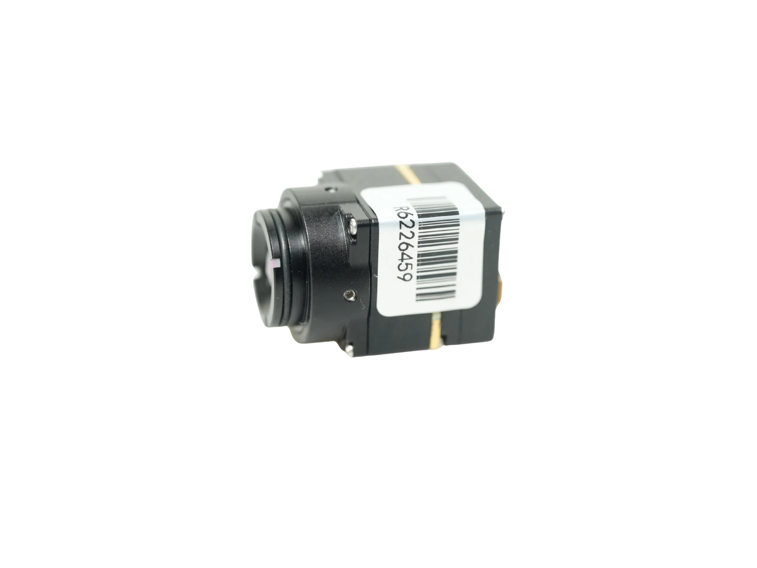
The HR-1280 is an advanced, ultra-high-resolution thermal imaging core designed specifically for engineering teams building high-tier enterprise UAV payloads, wide-area search and recovery platforms, and industrial machine vision systems. Built around an uncooled Vanadium Oxide (VOx) focal plane array with a 12 μm pixel pitch and native 1280×1024 resolution, the HR-1280 captures fine thermal details that lower-resolution cores miss.
Operating across the 8–14 μm spectral response band at a smooth 50 Hz frame rate, the module features a thermal sensitivity of ≤35 mK (at 25°C, F#1.0). This level of sensitivity enables detection of subtle biological heat signatures under partial foliage cover and in challenging environmental conditions. The core weighs just 68 grams (without lens) and features a compact 35×35×35 mm chassis, making it suitable for integration into multi-axis aerial gimbals.
The HR-1280 provides comprehensive industrial interface support, including BT656, BT1120, SDI, and CameraLink digital baseband outputs, paired with RS232, RS485, and RS422 serial communication buses. Operating across a wide 5 to 24 V DC input range, it integrates seamlessly into industrial drone electrical architectures. Optical flexibility is supported through a wide range of factory lens options (9 mm, 13 mm, 19 mm, 25 mm, 35 mm, 50 mm, 75 mm, and 100 mm). (Note: CVBS analog output is not natively supported; analog requirements should be reviewed during RFQ planning. NDAA compliance statements are available upon request.)
View Product Details & Pricing ➔
Product Profile 2: MD-64CA 640×512 Uncooled VOx Thermal Imaging Camera Module
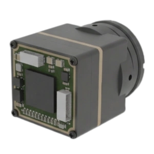
The MD-64CA is an ultra-compact, lightweight thermal camera core optimized for SWaP-constrained aerial platforms, sub-2 kg hunting drones, micro-gimbal systems, and low-latency tracking payloads. Featuring a 640×512 uncooled VOx microbolometer array with a 12 μm pixel pitch and 50 Hz refresh rate, the MD-64CA delivers high imaging performance while weighing only 23.1 grams and consuming less than 0.7 Watts during continuous operation.
Boasting a thermal sensitivity of ≤30 mK (F1.0), the MD-64CA excels in resolving low-contrast wildlife targets during thermal crossover periods. It supports an operating input voltage range of 5 to 24 V DC and an operating temperature envelope spanning -20°C to +60°C. The core provides flexible output interfaces, supporting analog CVBS video for low-latency transmission (<20 ms reference delay), as well as USB UVC and MIPI CSI-2 digital pipelines for integration with companion edge AI single-board computers.
The MD-64CA features factory-installed, fixed-focus optics aligned during production to ensure optical boresight stability under aerial flight vibration. The table below details factory optical configurations and calculated Johnson Criteria target ranges modeled for a standard human/large game target (1.8 × 0.5 × 0.3 m):
| Focal Length | Field of View (FOV) | IFOV | Detection Range | Recognition Range | Identification Range |
|---|---|---|---|---|---|
| 4.9 mm | 76.2° × 64.2° | 2.45 mrad | 476 m | 119 m | 60 m |
| 9.1 mm | 45.8° × 37.3° | 1.31 mrad | 884.72 m | 221.18 m | 110.59 m |
| 13.0 mm | 33.0° × 26.6° | 0.92 mrad | 1,263.89 m | 315.97 m | 157.99 m |
| 19.0 mm | 22.9° × 18.4° | 0.63 mrad | 1,847.22 m | 461.81 m | 230.90 m |
| 35.0 mm | 12.5° × 10.0° | 0.34 mrad | 3,402.78 m | 850.69 m | 425.35 m |
Note: The 4.1 mm ultra-wide-angle lens option is available upon request, with final FOV and mechanical drawings confirmed during quotation. Distance estimates represent Johnson Criteria mathematical calculations under standard atmospheric transmission.
View Product Details & Pricing ➔
7. Systems Engineering & Integration Checklist
Before releasing PCB fabrication runs, machining gimbal enclosures, or signing off on OEM purchase orders, engineering teams should execute this detailed system checklist:
-
1. Optical & Mission Flight Profile Validation:
- ⚙️ Establish strict operational altitude envelopes (e.g., 40–60 m AGL brush penetration vs. 100–120 m AGL standoff surveys).
- ⚙️ Verify Ground Sample Distance (GSD) targets to ensure Johnson Criteria Identification thresholds are met for your target species.
- ⚙️ Select and lock optical focal lengths (9.1 mm for wide swath coverage vs. 19 mm/35 mm for high-standoff animal tracking).
- ⚙️ Confirm Germanium optical elements specify Diamond-Like Carbon (DLC) hard exterior coatings to survive dust, rotor wash, and rain.
-
2. Gimbal Mechanics & Thermal Management:
- ⚙️ Calculate total Center of Gravity (CoG) for core, mount brackets, and optics across pitch, roll, and yaw axes.
- ⚙️ Design direct conductive heat sinking from the core chassis to the outer aluminum gimbal frame to stop heat buildup at the FPA.
- ⚙️ Confirm mechanical clearance for rear-exit ribbon cables, high-flex wiring harnesses, and silicone vibration dampers.
- ⚙️ Verify total payload mass against brushless motor torque curves to prevent motor saturation during rapid aircraft yaw.
-
3. Electrical Power & Signal Interface Integrity:
- ⚙️ Confirm power bus stability (5–24 V DC) and ensure supply ripple stays below 30 mVp-p to prevent microbolometer read noise.
- ⚙️ Select your video pipeline: Analog CVBS (<20 ms latency), MIPI CSI-2 (raw radiometric AI detection), or digital baseband (SDI/BT1120).
- ⚙️ Map out serial control lines (UART/RS232/RS485) to send palette switching, digital zoom, and manual NUC shutter commands.
- ⚙️ Implement dedicated copper shielding and common-mode chokes to isolate payload video lines from ESC switching noise and motor EMI.
-
4. Regulatory Compliance, Software, & Supply Chain:
- ⚙️ Review regional export compliance frameworks (ITAR, EAR dual-use, 50 Hz civil exemptions) for target deployment zones.
- ⚙️ Secure OEM NDAA compliance certificates, origin documentation, and 3D STEP mechanical models.
- ⚙️ Verify host software driver compatibility (Linux V4L2, ROS nodes, OpenCV, or vendor-supplied C/Python SDKs).
8. Deep-Dive Frequently Asked Questions
Are thermal imaging drones legally compliant for hunting and wildlife recovery operations?
Here is where thermal drones are actively permitted and widely deployed: First, post-shot game recovery. In many states, commercial operators are legally authorized to locate downed deer or elk to prevent carcass spoilage, provided all hunting weapons are cased and the harvest has already taken place. Second, invasive species eradication and agricultural control. Airborne thermal payloads are heavily used to locate and eradicate destructive feral hog sounders, manage coyote predation, and conduct official state wildlife headcounts. Make sure you check local DNR regulations and equip your platform with a high-resolution sensor (640×512 or 1280×1024) to ensure positive target identification so you never confuse livestock with game.
What are the primary optical and resolution trade-offs between 640×512 and 1280×1024 cores for aerial game recovery?
Alternatively, you can double the focal length on a 1280 core to maintain your FOV while doubling magnification. That lets you fly at 120 m AGL instead of 60 m AGL while keeping the exact same number of pixels on target, keeping motor noise completely inaudible to wildlife. But the 1280 core is heavier (68 g vs 23.1 g), requires larger Germanium optics, and pushes over 1 Gbps of raw bandwidth across the digital bus. If you are building for a sub-2 kg drone or micro-gimbal, a 640×512 core like the MD-64CA paired with a 13 mm or 19 mm lens gives you the best balance of thermal resolution, battery life, and compact packaging.
How does microbolometer NETD sensitivity affect wildlife detection through tree canopies?
On top of that, an animal’s insulating fur coat means its surface radiant temperature is often only 0.5°C to 1.5°C warmer than the surrounding cold forest floor. If your core has a standard industrial NETD of ≥50 mK, that faint thermal signature gets completely buried in the sensor’s own background noise floor. But when you deploy a high-sensitivity VOx core rated at ≤30 mK or ≤35 mK (at 25°C, F1.0), the sensor easily pulls out 0.03°C temperature variations. That extra sensitivity lets the onboard image processing engine pull those tiny thermal blooms out from under the leaves, giving you clean target detection where cheaper cores show only gray, muddy background noise.
📚 References & Further Reading
- Industry Standard: Industrial surveillance and optical modeling architectures via Axis Communications and Bosch Security Systems.
- Related Guide: Hardware wiring, signal protocols, and video transmission in our guide on CVBS thermal camera module analog video integration.
- Technical Knowledge Base: Deep-dive sensor physics, radiometric calibration, and lens calculations in the Camcuda Thermal Imaging Guides.
- Component Sourcing: Full OEM thermal cores, uncooled LWIR modules, and lens configurations in the Camcuda Product Catalog.