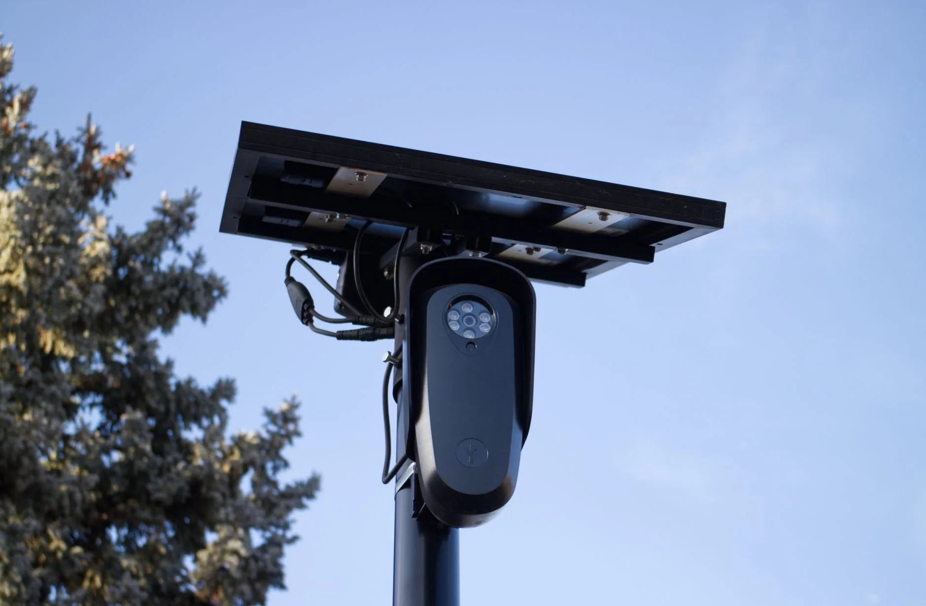
Cheap Thermal Infrared Camera vs OEM Cores: Engineering Buyer’s Guide
Cheap Thermal Infrared Camera vs OEM Cores: Engineering Buyer’s Guide
Every hardware engineer and procurement lead building an industrial machine vision rig, an autonomous mobile robot (AMR), a thermal drone payload, or a factory condition monitoring system hits the exact same fork in the road. On one side, you have cheap consumer thermal cameras, pocket diagnostic gadgets, and smartphone dongles selling between $200 and $600. On the other side, bare OEM Long-Wave Infrared (LWIR) sensor cores and multi-spectrum edge-AI tracking modules run anywhere from several hundred to a few thousand bucks. When project budgets get tight, someone in the room will inevitably ask: “Can’t we just buy a bunch of cheap consumer units, rip the plastic enclosures off, and hook them up to our embedded boards?”
Here’s the deal: on paper, that hack looks like an easy win to shave a few grand off your Bill of Materials (BOM). But once you get those budget units on the test bench, the engineering reality hits hard. Budget consumer thermal gadgets hit their low price points by cutting every corner imaginable on sensor physics, optical throughput, thermal stabilization, and digital interface architecture. You end up wrestling with tiny 80×60 or 120×90 microbolometer dies, sluggish 9 Hz export-capped frame rates, noisy thermal baselines (NETD north of 70 mK to 100 mK), and closed USB stacks that drop frames like clockwork.
If you try to drop a consumer thermal dongle into a 24/7 industrial inspection line, a closed-loop motor control setup, or an uncooled aerial targeting gimbal, things fall apart fast. You run into uncalibrated thermal drift, sensor saturation, motion blur, and brutal integration headaches. This guide cuts through the marketing fluff to break down the cold, hard physics and low-level data pipelines separating budget consumer gadgets from true factory-grade OEM cores, giving you a no-nonsense roadmap covering sensor physics, hardware buses, optical selection, and total cost of ownership (TCO).
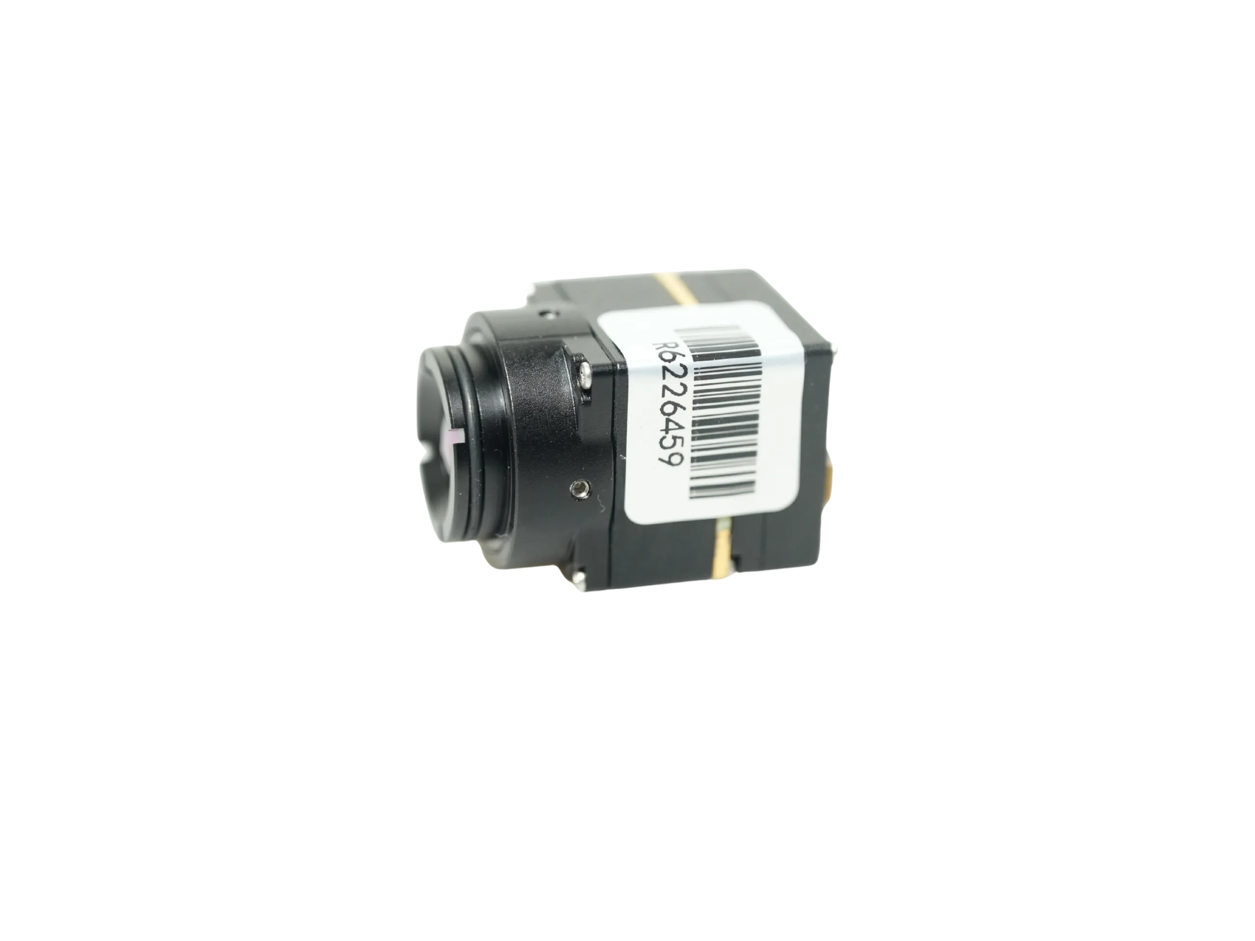
Table of Contents
- 👉 1. The Anatomy of “Cheap” Thermal Cameras: False Economies in Embedded Design
- 👉 2. Core Sensor Physics: Uncooled VOx FPAs vs. Low-Cost Thermopiles & Microbolometers
- 👉 3. Video Pipeline & Digital Interfaces: Consumer USB vs. MIPI CSI-2 & Industrial Streaming
- 👉 4. Edge AI & UAV Integration: Telemetry, SWaP-C, and Low-Latency Targeting
- 👉 5. Commercial OEM Thermal Modules: Technical Showcases & Specifications
- 👉 6. Bill of Materials (BOM) & TCO: Hidden Engineering Costs of Consumer Conversion
- 👉 7. Frequently Asked Questions (FAQ)
1. The Anatomy of “Cheap” Thermal Cameras: False Economies in Embedded Design
When you are designing an automated optical inspection (AOI) jig, an autonomous mobile robot, or a continuous security monitoring node, building around a consumer-grade thermal imager creates massive architectural bottlenecks right out of the gate. That low shelf price masks hard design compromises made for intermittent, handheld homeowner use rather than deterministic industrial uptime.
The first trap is fake spatial resolution driven by software upscaling. Consumer thermal imagers love to advertise display specs like 320×240 or 640×480 pixels. But when you tear down the hardware BOM, the actual microbolometer focal-plane array hidden behind the front window is often a measly 80×60 (4,800 active pixels) or 120×90 (10,800 active pixels). To make the image look sharp on a phone screen, the camera’s internal processor runs aggressive bicubic interpolation, unsharp masking, and edge-blending overlays from a cheap visible sensor. That might help a home inspector spot a missing fiberglass insulation batten behind drywall, but in automated computer vision, it is pure poison. When your algorithms need to measure absolute thermal gradients across a tiny surface-mount PCB trace or detect delamination in a composite aircraft skin, interpolated pixels deliver pure mathematical noise, triggering endless false positives and missed defects.
The second major roadblock is frame rate throttling. To dodge international export controls—specifically US ITAR regulations and Wassenaar Arrangement dual-use restrictions—consumer thermal cameras are intentionally hard-locked to ≤8.7 Hz (marketed as 9 Hz). A 9 Hz thermal feed is fine if a technician is standing still pointing a diagnostic gun at a static breaker box. But try mounting that same 9 Hz camera on an automated conveyor moving at 1.5 meters per second, a robotic arm picking parts, or a drone flying at 35 mph. The feed turns into a smeared mess of motion blur, tearing, and dropped frames. In contrast, genuine industrial OEM thermal cores run at native 50 Hz or 60 Hz frame rates, giving you the temporal resolution needed for tight closed-loop motor control and crisp frame-by-frame image tracking.
Then comes thermal drift and Non-Uniformity Correction (NUC). Every uncooled microbolometer drifts as its substrate warms up from internal electronics and ambient temperature swings. Industrial OEM modules handle this with a built-in electromechanical shutter driven by a precision solenoid. Every few minutes, the shutter snaps shut for a fraction of a second to perform a single-point flat-field calibration against a uniform thermal baseline, referencing multi-temperature calibration curves stored in onboard EEPROM. Cheap consumer units ditch this physical shutter mechanism entirely to save a couple of dollars on the BOM. Instead, they rely on crude “shutterless” software algorithms or expect a human to manually slap a lens cap on. In real industrial environments where factory ambient temperatures swing from 15°C in the morning to 40°C in the afternoon, shutterless consumer units drift blindly, showing false hot spots and corrupting your inspection limits. For a deeper look at how long-wave cores handle severe industrial environments, check out our engineering breakdown on uncooled LWIR thermal modules for outdoor security and industrial monitoring.
2. Core Sensor Physics: Uncooled VOx FPAs vs. Low-Cost Thermopiles & Microbolometers
To really evaluate thermal camera hardware, you have to look past the spec sheet marketing and dive into detector physics, noise floors, and optical aperture math. The gold standard for measuring thermal detector sensitivity is Noise Equivalent Temperature Difference (NETD), expressed in millikelvins (mK). NETD tells you the smallest target temperature differential that produces a signal-to-noise ratio (SNR) of exactly one at the sensor readout. Here is the fundamental physics equation governing NETD:
NETD = (4 × F² × Vn) / (τ × Ad × (ΔV / ΔT) × (ΔL / ΔT))
Look closely at the variables in that formula:
- ⚙️ F: Optical system F-number (aperture ratio).
- ⚙️ Vn: Broadband noise voltage of the detector material.
- ⚙️ τ: Spectral transmission efficiency of the Germanium/Chalcogenide optical stack.
- ⚙️ Ad: Active surface area of an individual microbolometer pixel.
- ⚙️ (ΔV / ΔT): Thermal responsivity of the microbolometer detector layer.
- ⚙️ (ΔL / ΔT): Blackbody spectral radiance derivative across the 8 to 14 μm LWIR atmospheric window.
High-end industrial OEM thermal cores use Vanadium Oxide (VOx) thin-film microbolometer arrays. VOx gives you a massive Temperature Coefficient of Resistance (TCR) combined with exceptionally low 1/f flicker noise. This allows factory-grade VOx cores to hit NETD ratings of ≤30 mK to ≤40 mK when paired with fast F/1.0 lenses. In plain English, a sensor rated at ≤30 mK cleanly resolves temperature differences as small as 0.03°C. That kind of sensitivity is what lets you spot micro-delamination inside composite panels, tiny millivolt drops across micro-vias on a dense multi-layer PCB, or low-contrast human targets hiding in heavy brush.
On the flip side, sub-$500 thermal devices routinely use cheap Amorphous Silicon (α-Si) or low-density thermopile arrays. While α-Si can be churned out cheaply on standard silicon fab lines, it suffers from a much lower TCR and significantly higher raw noise voltage (Vn). That balloons the NETD to 70 mK, 100 mK, or worse. When a sensor has an NETD of 100 mK, it needs a full 0.10°C delta just to pull a signal out of its own noise floor. If your machine vision setup is trying to catch subtle thermal variations, an α-Si sensor simply washes out the details in a sea of analog noise.
Pixel pitch is another critical parameter. Modern OEM cores use tight 12 μm lithography, whereas legacy or budget microbolometers are stuck on older 17 μm or 25 μm processes. Moving down to a 12 μm pitch means a smaller focal-plane array captures the exact same resolution. That directly reduces the optical focal length required to hit a specific Instantaneous Field of View (IFOV):
IFOV = Pixel Pitch (d) / Focal Length (f)
Because optical-grade Germanium is precious and expensive, reducing the required focal length cuts down the physical diameter, thickness, and raw weight of the lens assembly. However, consumer manufacturers often cut optical costs further by swapping out pure Germanium for cheap molded Chalcogenide glass or wafer-level silicon optics with slow apertures (F/1.3 to F/1.5). Look back at the NETD equation: because the F-number is squared (F²), bumping your lens from F/1.0 to F/1.4 cuts your optical throughput in half and doubles your system noise. High-performance OEM cores maintain peak thermal sensitivity by running fully coated, anti-reflective (AR) Germanium glass with wide F/1.0 apertures across all standard lens options.
3. Video Pipeline & Digital Interfaces: Consumer USB vs. MIPI CSI-2 & Industrial Streaming
If you have ever tried hooking an external sensor up to an NVIDIA Jetson, Raspberry Pi CM4, NXP i.MX8, or custom FPGA compute board, you know that the physical interface and software driver stack make or break your timeline. Consumer thermal gadgets create an absolute nightmare for embedded developers due to their locked-down hardware architecture.
Most consumer thermal dongles run over a standard USB-C or Lightning plug designed strictly to talk to a proprietary iOS or Android app. Their internal processor takes raw microbolometer readings, converts them into a proprietary compressed format, and pushes them down a closed pipeline. Getting that data into a headless Linux system, ROS (Robot Operating System), or a real-time RTOS requires reverse-engineering undocumented USB endpoints, handling messy packet handshakes, and living with unpredictable 150 ms to 300 ms latency spikes. And if the manufacturer pushes an unannounced firmware change or deprecates their mobile app, your entire production build breaks without recourse.
Factory OEM thermal cores avoid this entirely by exposing raw, deterministic, industrial-grade hardware interfaces:
- ✅ MIPI CSI-2 (Camera Serial Interface): The gold standard for embedded edge computing. MIPI CSI-2 runs high-speed differential serial lanes directly into the host processor’s Image Signal Processor (ISP). This enables zero-copy Direct Memory Access (DMA) of uncompressed pixel data straight into system memory, hitting end-to-end pipeline latencies under 10 milliseconds.
- ✅ Driverless USB Video Class (UVC): For industrial x86 or ARM PCs running Linux or Windows, OEM cores provide compliant UVC endpoints. You plug the module in, and it instantly exposes a native Video4Linux2 (V4L2) node. No custom kernel hacks or third-party bloatware required—just clean, native integration into OpenCV, GStreamer, and ROS nodes.
- ✅ Parallel CMOS / DVP: Direct parallel bus connections (VSYNC, HSYNC, PCLK, and parallel data lines) for hookups to low-cost microcontrollers, DSPs, and custom FPGAs where high-speed serial transceivers are overkill.
- ✅ Composite Video (CVBS): True zero-latency analog output for direct wiring into rugged display panels, legacy diagnostic monitors, or analog 5.8 GHz video transmitters on compact UAV builds.
Crucially, OEM cores stream uncompressed 14-bit or 16-bit raw digital radiometric data. In a true 14-bit radiometric stream, every pixel value is a direct linear representation of absolute emitted infrared energy. This lets your onboard algorithms calculate exact surface temperatures for every single pixel across the entire field of view:
TObject (°C) = (Digital Number × Scale Factor) − Offset Calibration Value
In contrast, consumer thermal dongles do all their processing internally and spit out a lossy 8-bit RGB color palette (like Ironbow or White-Hot). Once that raw radiometric data is compressed into an 8-bit color space, the underlying absolute temperature metadata is permanently destroyed. Your host computer can no longer run precision temperature thresholding, automated alarm triggers, or quantitative computer vision—you are stuck looking at a colored picture.
4. Edge AI & UAV Integration: Telemetry, SWaP-C, and Low-Latency Targeting
When you are building aerial payloads, perimeter security nodes, or autonomous mobile robots, thermal modules have to hit strict Size, Weight, Power, and Cost (SWaP-C) targets while giving your edge AI processors enough clean data to do their job.
Modern dual-spectrum targeting setups pair an electro-optical (EO) visible sensor with an uncooled VOx long-wave thermal core on a single edge-compute platform. Visible sensors provide crisp 1080p or 4K detail during bright daylight, but they are completely blind in zero-light, heavy fog, smoke, or high-glare environments. Long-wave thermal channels cut straight through visual obscurants, mapping surface heat into clean contrast. By feeding both streams directly into an onboard Neural Processing Unit (NPU), the system can execute real-time object tracking, sensor fusion, and picture-in-picture (PIP) displays entirely at the edge without chewing up RF downlink bandwidth.
When spec’ing a dual-spectrum edge-AI thermal payload, keep these hardware requirements top of mind:
- ⚙️ Dedicated NPU Acceleration: Modern edge-AI payloads carry dedicated NPUs kicking out 6 TOPS (Tera-Operations Per Second) or more. This onboard compute horsepower lets you run dense object detection architectures (like YOLOv8 or custom CNNs) directly on the payload, driving tracking latencies down to an ultra-fast 8 milliseconds.
- ⚙️ High-Speed Multi-Target Tracking: High-performance vision processors can track up to 120 dynamic targets simultaneously. Advanced tracking routines include reticle locking, trajectory prediction, and lost-target re-acquisition capable of holding locks on vehicles moving at relative speeds up to 450 km/h.
- ⚙️ Standard Flight Telemetry Protocols: Unmanned systems demand plug-and-play compatibility with standard flight controller stacks like ArduPilot and PX4. Payloads should communicate natively over CRSF or MAVLink, allowing ground control stations (like Mission Planner or QGroundControl) to switch palettes, toggle electronic stabilization, command optical zoom, and transmit target coordinates over existing telemetry streams.
- ⚙️ SWaP-C Optimization: Every gram matters on an aerial payload. Bare OEM thermal cores weigh as little as 23 grams and pull under 0.7 Watts of DC power, leaving your power budget intact for flight motors and gimbal stabilization.
5. Commercial OEM Thermal Modules: Technical Showcases & Specifications
For systems engineers selecting factory-grade thermal hardware, the following sections provide detailed technical specifications for two production-grade solutions: the standalone MD-64CA uncooled VOx core and the TM02-SOLO T dual-spectrum edge-AI UAV tracking module. If your development scope calls for an entry-level evaluation core, review the TC160-NF 160×120 LWIR Thermal Imaging Module, or explore our engineering library in the Camcuda technical blog index.
Product Showcase 1: MD-64CA 640×512 Uncooled VOx Thermal Imaging Camera Module
The MD-64CA is an ultra-compact, uncooled long-wave infrared (LWIR) camera module engineered specifically for OEM equipment integration, embedded machine vision, handheld industrial instruments, border security nodes, robotics, and UAV payload evaluation. Built around a high-density 640×512 Vanadium Oxide (VOx) focal-plane array with a 12 μm pixel pitch, the MD-64CA delivers native 50 Hz video output in an ultra-low-power, lightweight format.
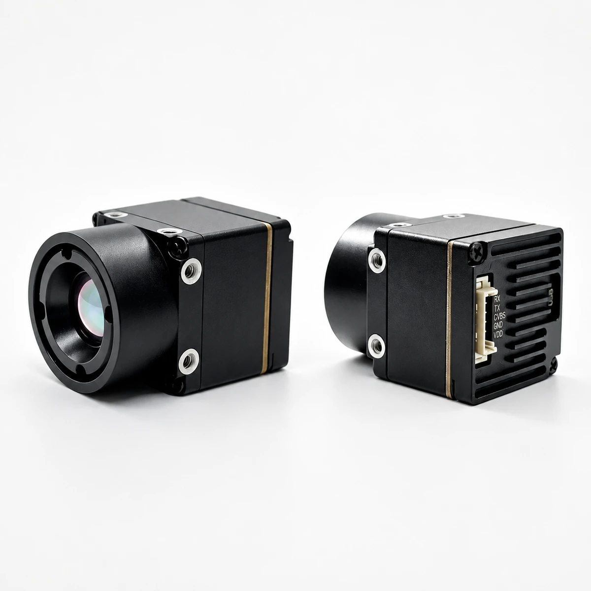
| Specification Parameter | Technical Detail / Reference Value |
|---|---|
| Model Identifier | MD-64CA |
| Detector Type | Uncooled Vanadium Oxide (VOx) Focal-Plane Array |
| Array Resolution | 640 × 512 Active Pixels |
| Pixel Pitch | 12 μm |
| Spectral Response Range | 8 to 14 μm (LWIR) |
| Thermal Sensitivity (NETD) | ≤30 mK (at F1.0 reference) |
| Native Frame Rate | 50 Hz |
| Factory-Installed Lens Options |
4.9 mm (76.2° × 64.2° FOV, F1.0) 9.1 mm (45.8° × 37.3° FOV, F1.0) 13 mm (33.0° × 26.6° FOV, F1.0) 19 mm (22.9° × 18.4° FOV, F1.0) 35 mm (12.5° × 10.0° FOV, F1.0) |
| Available Video Interfaces | CVBS (Analog), USB UVC (Digital), MIPI CSI-2 |
| Operating Voltage Range | 5 to 24 V DC Wide Input |
| Module Power Consumption | < 0.7 Watts |
| Operating Temperature Range | -20°C to +60°C |
| Total Bare Module Weight | 23.1 grams |
Integration & Engineering Checklist for the MD-64CA:
- ⚙️ Optics Selection: Lock down your required focal length (4.9 mm up to 35 mm) during initial quoting. Lenses are factory-threaded, optical-aligned, and thermal-calibrated; they are not swappable in the field.
- ⚙️ Electrical Interface Definition: Verify whether your host carrier board needs raw MIPI CSI-2 lanes, plug-and-play USB UVC, or CVBS analog before freezing your custom wiring harnesses.
- ⚙️ Thermal Conduction Path: Make sure your carrier enclosure provides a direct metal-to-metal thermal interface or thermal gap pad against the core chassis to keep it well within the -20°C to +60°C operating envelope.
- ⚙️ Clean Power Delivery: Feed the unit clean, filtered 5V to 24V DC to eliminate switching noise during initial microbolometer bias stabilization.
View Product Details & Pricing ➔
Product Showcase 2: 6 TOPS Dual-Spectrum UAV AI Tracking Module with 640×512 Thermal Camera
The TM02-SOLO T is an integrated dual-spectrum electro-optical (EO) and long-wave infrared (LWIR) AI-tracking subsystem designed for UAV OEMs, autonomous robotics developers, and security system integrators. By combining a 1080p 120 Hz visible camera, a 640×512 uncooled VOx thermal camera, and a dedicated 6 TOPS edge-AI compute board, the TM02-SOLO T executes real-time vehicle and personnel tracking across daylight, zero-light, and smoke-obscured scenes entirely onboard the aircraft.
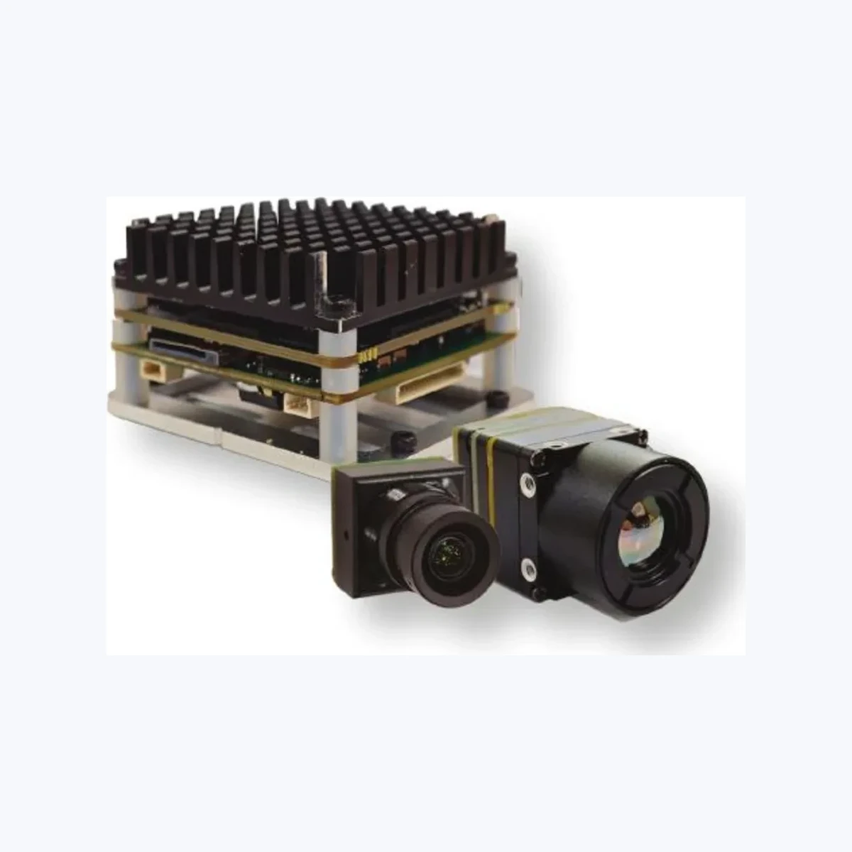
| Subsystem Category | Engineering Specification Parameter | Reference Value / Capability |
|---|---|---|
| Edge AI & Tracking Subsystem | Product Model | TM02-SOLO T |
| Target Classifications | Personnel, Ground Vehicles, Custom User Classes | |
| Detection Distance Reference | Vehicles: Up to 400 m; Personnel: Up to 170 m | |
| Minimum Resolvable Target Size | 10 × 10 Active Pixels | |
| Processing Pipeline Latency | 8 ms (Supplier bench test reference) | |
| Dynamic Target Tracking Speed | Up to 450 km/h relative motion | |
| Tracking & Display Modes | Reticle locking, close-to-lock, route pre-map, lost-target recall, PIP | |
| Compute & Flight Control | Dedicated AI Acceleration | 6 TOPS Neural Processing Unit |
| CPU Architecture | Arm Cortex-A76 (2.4 GHz) + Quad-Core Cortex-A55 (1.8 GHz) | |
| Control & Telemetry Protocols | CRSF and MAVLink Protocol Support | |
| Flight Controller Compatibility | BetaFlight, ArduPilot, PX4 Autopilot Platforms | |
| Recommended Input Voltage | Regulated 9 to 16 V DC | |
| Board Dimensions & Mount Pattern | 45 × 45 × 26 mm (Standard 42.5 × 42.5 mm mounting) | |
| Visible (EO) Camera Specs | Optical Sensor Format | 1/1.8-inch CMOS Optical Sensor |
| Focal Length & FOV | 8.45 mm (Diagonal 66.3° / Horizontal 57.1° / Vertical 30.4°) | |
| Minimum Scene Illumination | 0.001 lux Low-Light Reference | |
| Resolution & Native Frame Rate | 1920 × 1080 (1080p) at 120 Hz | |
| Physical Camera Head Size | 25.5 × 19.5 × 19.5 mm | |
| Thermal (LWIR) Camera Specs | Focal-Plane Array Detector | Uncooled Vanadium Oxide (VOx) |
| Spectral Range & Pixel Pitch | 8 to 14 μm (LWIR), 12 μm Pixel Pitch | |
| Thermal Resolution & Rate | 640 × 512 at 50 Hz Native Output | |
| Focal Length & Thermal FOV | 9.1 mm (Diagonal 61.8° / Horizontal 47.7° / Vertical 38.2°) | |
| Host Board Interconnect | MIPI High-Speed Interconnect Bus | |
| Primary Function Scope | AI Target Tracking & Visual Observation (Non-Radiometric Reference) |
Integration Notes for UAV System Architects: The thermal channel on the TM02-SOLO T is tuned for high-contrast spatial awareness, object acquisition, and real-time AI bounding box tracking. It is built for detection and pursuit, not absolute calibrated thermography. For clean aerial integration, provide regulated 9V to 16V DC power with dedicated ground isolation to prevent motor switching ripple from the Electronic Speed Controllers (ESCs) from bleeding into the high-gain analog sensor front-end.
View Product Details & Pricing ➔
6. Bill of Materials (BOM) & TCO: Hidden Engineering Costs of Consumer Conversion
In the shop, selecting a $300 consumer thermal gadget over a $1,000 factory OEM core might make your prototype BOM look great on an initial spreadsheet. But down in the trenches, a realistic Total Cost of Ownership (TCO) analysis proves that Non-Recurring Engineering (NRE) costs and field maintenance will wipe out those initial savings in no time.
Look at the mechanical packaging reality first. Consumer cameras come enclosed in glued ABS plastic shells or over-molded rubber grips. Once you strip the shell, you find fragile flexible printed circuits (FPCs) soldered directly between boards without a single mounting hole, alignment pin, or structural standoff. To mount that decased sensor securely into an industrial chassis, your team has to burn engineering hours designing custom CNC brackets or 3D fixtures. In high-vibration environments—like an industrial gantry or a multirotor frame—unsupported ribbon cables and solder joints fracture and fail. True OEM cores, on the other hand, come housed in CNC-machined aluminum chassis with standard M2/M3 mounting holes aligned precisely to the optical center line.
Then you hit the thermal dissipation wall. An uncooled microbolometer continuously pumps out heat from its Readout Integrated Circuit (ROIC). If you do not provide a direct thermal conduction path, that heat builds up unevenly across the sensor die, showing up as massive thermal vignetting and non-uniform shading across your image. Bare OEM cores feature precision-machined thermal contact pads engineered to mate directly to chassis heat sinks with standard thermal gap pads. Consumer dongles rely on ambient airflow inside their plastic housing; seal them inside an IP67 enclosure, and they quickly overheat, saturate the sensor, and crash your measurement pipeline.
Finally, there is the ongoing software maintenance headache. Consumer hardware relies on closed, proprietary mobile drivers. If the vendor updates their firmware or drops support for their mobile app, your custom reverse-engineered driver stack breaks instantly. Bare OEM cores come backed by clean, fully documented C/C++ SDKs, standard Linux V4L2 kernel compatibility, ROS nodes, and guaranteed production lifecycles spanning 5 to 7 years. When you factor in custom driver dev time, broken mechanical fixtures, and field failure rates, starting with a true OEM core is the cheaper, faster engineering choice every single time.
7. Frequently Asked Questions (FAQ)
What is the practical difference between a cheap $300 thermal camera and a commercial OEM thermal core?
Can budget thermal cameras be integrated into UAV payloads or custom diagnostic devices?
Why do low-cost thermal cameras fail in precise electronics inspection and distant outdoor detection?
📚 References & Further Reading
- Industry Standard: MAVLink Micro Air Vehicle Telemetry Protocol Specifications
- Industry Standard: MIPI Alliance Camera Serial Interface 2 (CSI-2) Standard
- Related Product Guide: TC160-NF 160×120 LWIR Thermal Imaging Core Module
- Engineering Resource: Camcuda Industrial Vision & Thermal Engineering Blog
- Related Technical Article: Uncooled LWIR Thermal Modules for Outdoor Security and Industrial Monitoring