Cheap Infrared Camera vs. OEM Thermal Core: B2B Integration Guide
Cheap Infrared Camera vs. OEM Thermal Core: B2B Integration Guide
Engineering teams and system integrators building uncrewed aerial vehicles (UAVs), ruggedized ground robotics, and perimeter security platforms run into the classic build-versus-buy wall all the time. When procurement runs a search for a cheap infrared camera, they almost always land on consumer smartphone dongles, bare-bones thermopile arrays, or cheap CMOS security boards with the IR-cut filter popped off. On paper, it looks like an easy way to slash initial bill of materials (BOM) costs. But on the bench and out in the field, hacking consumer hardware into mission-critical embedded systems leads straight to severe software bottlenecks, thermal frame-rate throttling, horrific signal jitter, multi-frame latency, and complete target loss the second things get dynamic.
Here’s the deal: moving from off-the-shelf consumer gadgets to actual industrial OEM thermal cores and dual-spectrum AI modules isn’t just a spec-sheet upgrade. It comes down to raw electro-optical physics, non-uniformity calibration curves, edge compute pipelines, and deterministic flight control protocols. In this teardown, we’ll walk through the actual physical differences between cheap consumer infrared gear and production-grade Long-Wave Infrared (LWIR) cores, look at why budget hardware breaks down in real operational environments, break down detailed bench metrics for OEM tracking modules, and give you the blueprint for wiring dual-spectrum AI tracking directly into your airframes and edge compute nodes.
Table of Contents
- 👉 1. Physics & Spectrum: Near-Infrared (NIR) vs. Long-Wave Infrared (LWIR)
- 👉 2. The Engineering Traps of Budget Thermal Cameras
- 👉 3. Architectural Comparison: Consumer Gadgets vs. Industrial OEM Cores
- 👉 4. Dual-Spectrum OEM Modules: Hardware Specifications & Benchmark Data
- 👉 5. SWaP-C Optimization: Balancing Compute, Optics, and Sensor Pitch
- 👉 6. Flight Controller & Protocol Integration: ArduPilot, BetaFlight, and CRSF
- 👉 7. Step-by-Step B2B Procurement and Flight Validation Checklist
- 👉 8. Frequently Asked Questions (FAQ)
1. Physics & Spectrum: Near-Infrared (NIR) vs. Long-Wave Infrared (LWIR)
Let’s clear up the biggest source of confusion in early component sourcing: the sloppy use of the word “infrared.” Optical sensors operate across distinct bands of the electromagnetic spectrum, and each band is ruled by completely different semiconductor physics, atmospheric transmission windows, and optical glass limitations.
Most cameras sold online as “cheap infrared night vision” are nothing more than Near-Infrared (NIR) sensors running between 0.75 µm and 1.0 µm. These boards use standard silicon complementary metal-oxide-semiconductor (CMOS) image chips where the factory simply left off the standard IR-cut filter or put it on a mechanical switcher. Because silicon has a tiny bit of quantum efficiency below 1.0 µm, the camera picks up photons bounced back from active 850 nm or 940 nm LED floodlights.
Make no mistake: NIR hardware does not see heat or surface emissivity. Put one of these cameras out in an unlit clearing, thick fog, industrial smoke, or prop-wash dust, and the sensor goes pitch black the split second your target moves past the LED throw distance. Worse yet, that active LED floodlight turns your platform into an unmistakable optical beacon for anyone using basic night-vision gear, killing any chance of covert operations or discreet security monitoring.
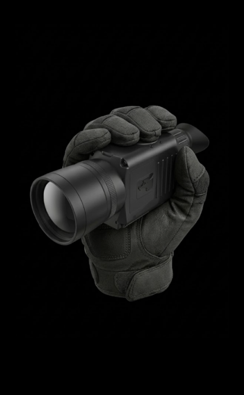
True thermal imaging takes place way out in the Long-Wave Infrared (LWIR) spectrum between 8.0 µm and 14.0 µm. Down in this atmospheric window, everything obeys Planck’s Radiation Law and the Stefan-Boltzmann Law. Every single object with a temperature above absolute zero constantly emits photons proportional to its emissivity and the fourth power of its absolute temperature ($E = \epsilon \sigma T^4$). You aren’t catching bounced light; you are reading pure radiated thermal energy straight off the target.
| Optical Band | Wavelength Range | Primary Semiconductor Material | Emission & Detection Physics |
|---|---|---|---|
| Visible Light | 0.38 µm – 0.75 µm | Silicon CMOS / CCD | Reflected ambient photon detection |
| Near-Infrared (NIR) | 0.75 µm – 1.0 µm | Enhanced Silicon CMOS | Reflected active LED illumination |
| Short-Wave IR (SWIR) | 1.0 µm – 2.5 µm | Indium Gallium Arsenide (InGaAs) | Reflected solar and atmospheric nightglow |
| Mid-Wave IR (MWIR) | 3.0 µm – 5.0 µm | InSb / MCT (Cryo-Cooled) | High-temperature thermal emission |
| Long-Wave IR (LWIR) | 8.0 µm – 14.0 µm | Vanadium Oxide (VOx) / a-Si | Passive, ambient thermal radiation |
Capturing those thermal photons demands uncooled microbolometers—tiny microscopic bridges fabricated from Vanadium Oxide (VOx) or Amorphous Silicon (a-Si) suspended over an integrated Read-Out Integrated Circuit (ROIC). When incoming thermal radiation hits the micro-bridge membrane, its temperature climbs, which changes its electrical resistance. The ROIC measures these tiny resistance shifts across the whole focal plane array at high speed without needing bulky cryocoolers or active floodlights.
If you’re mapping out sensor requirements for an upcoming build, take a look at our deep dive in the infrared camera module OEM buying guide. It covers microbolometer manufacturing methods, shutter calibration trade-offs, and how to maintain high scene contrast under poor weather conditions.
2. The Engineering Traps of Budget Thermal Cameras
Look, we have all seen a prototype team try to wire a cheap infrared camera dongle—built for home insulation checks—into a custom robotics payload. It looks tempting on paper during early phase-zero scoping. But once you start integrating the hardware into real autonomous loops, the whole setup falls apart.
| Technical Metric | Budget Consumer Dongle | Industrial Dual-Spectrum Core |
|---|---|---|
| Native Frame Rate | 8.7 Hz – 9.0 Hz (Export Capped) | 50 Hz – 60 Hz Native |
| Glass-to-Inference Latency | 120 ms – 300 ms (Buffered UVC) | 8 ms – 30 ms (Hardware Bus) |
| Digital Host Interface | Consumer USB-C / Lightning | MIPI-CSI2 / Direct Serial / FPC |
| Operational Thermal Range | 0°C to +35°C (High Drift) | -20°C to +60°C+ Industrial |
| Target Tracking Acceleration | None (Host CPU Bottleneck) | 4 TOPS – 6 TOPS Dedicated NPU |
| Autopilot Telemetry Support | Proprietary Closed Mobile App | CRSF, BetaFlight, ArduPilot |
The first major roadblock is the 9 Hz export ceiling. Under international dual-use export rules (including Wassenaar Arrangement agreements and US EAR controls), thermal cores pushing frame rates above 9 Hz face strict regulatory and export tracking. To bypass that licensing overhead and ship consumer dongles globally, manufacturers throttle their internal sensor clocks down to 8.7 Hz or 9.0 Hz.
Think about what that means on an airframe cruising at 25 meters per second (roughly 55 mph). At 9 Hz, your camera grabs a single frame every 2.78 meters of flight distance. Standard tracking pipelines like ByteTrack or DeepSORT rely heavily on bounding-box overlap between frames to maintain target identification. When your target shifts dozens of pixels between ticks because of platform motion, the tracking algorithm breaks down, loses association, and starts violently hunting across the frame.
The second trap is bus latency and signal jitter. Consumer gadgets wrap their video streams in OS-level USB Video Class (UVC) protocols. That means incoming frames get passed through USB host controllers, operating system ring buffers, driver translations, and software color conversions. By the time your application code reads the frame buffer, you’re sitting on 120 ms to 300 ms of glass-to-inference lag. Try feeding that delayed signal into an active PID flight controller or gimbal tracking loop: the phase lag induces aggressive control oscillations that will shake your gimbal apart or destabilize the airframe.
Finally, cheap sensors skimp on temperature-compensated Non-Uniformity Correction (NUC). In the field, temperatures swing wildly—from baking under direct sun to freezing in high-altitude prop-wash, not to mention heat blooming off internal ESCs. Without high-order polynomial look-up tables and precision internal mechanical shutters, raw microbolometer outputs drift instantly, burying your target under severe spatial fixed-pattern noise (FPN) and heavy vignetting.
3. Architectural Comparison: Consumer Gadgets vs. Industrial OEM Cores
When you’re designing vision payloads for autonomous industrial applications, the internal architecture makes or breaks your system reliability. The gap between cheap consumer dongles and industrial dual-spectrum OEM cores comes down to internal compute topologies, sensor synchronization, and optical physics.
A typical consumer thermal gadget is built around an uncalibrated microbolometer wired to a cheap USB bridge chip. That bridge compresses analog feeds into a basic UVC stream sent over a consumer-grade USB-C port. Your host single-board computer (SBC) has to ingest that USB stream, uncompress the frames, run thermal palette mapping, try to sync it with a separate visible light camera, and run object detection models on its already-loaded CPU or GPU. This setup chokes host buses, spikes compute thermals, and creates multiple vibration failure points across loose cables.
Industrial OEM dual-spectrum AI cores take a completely integrated, edge-first approach. The module mounts a high-resolution Long-Wave Infrared sensor and an ultra-low-light visible sensor onto a unified, CNC-machined structural base. Both imaging sensors pipe raw, uncompressed pixel data directly into an onboard System-on-Chip (SoC) packed with high-efficiency ARM cores and a hardware Neural Processing Unit (NPU) cranking out 4 to 6 TOPS of edge AI compute.
In this edge-native design, pixel-accurate optical alignment, Picture-in-Picture (PIP) composition, sensor fusion, and deep neural inferencing all run on the camera board itself. You don’t flood host buses with raw video streams. Instead, the camera core runs target detection models at native 50 Hz to 120 Hz rates and fires compact, deterministic coordinate error vectors ($\Delta X, \Delta Y$) straight to the flight controller over low-latency serial protocols like CRSF.
Optics are another massive differentiator. Standard optical glass (like BK7 or fused silica) is completely opaque to long-wave thermal infrared. Thermal radiation demands exotic optical materials—mainly single-crystal Germanium (Ge) or chalcogenide glass alloys. Industrial OEM cores house precision-ground Germanium lens elements coated in multi-layer Diamond-Like Carbon (DLC) and Anti-Reflective (AR) treatments, ensuring maximum infrared transmission, extreme scratch resistance, and rock-solid optical stability across wide operating temperatures.
4. Dual-Spectrum OEM Modules: Hardware Specifications & Benchmark Data
For systems engineers looking to eliminate processing bottlenecks and hardware drift, the modules below combine high-resolution 640×512 uncooled VOx thermal cores, high-frame-rate visible light sensors, and onboard edge AI processing in ultra-compact, lightweight packages.
Product Model: TM02-SOLO T Dual-Spectrum UAV AI Tracking Module
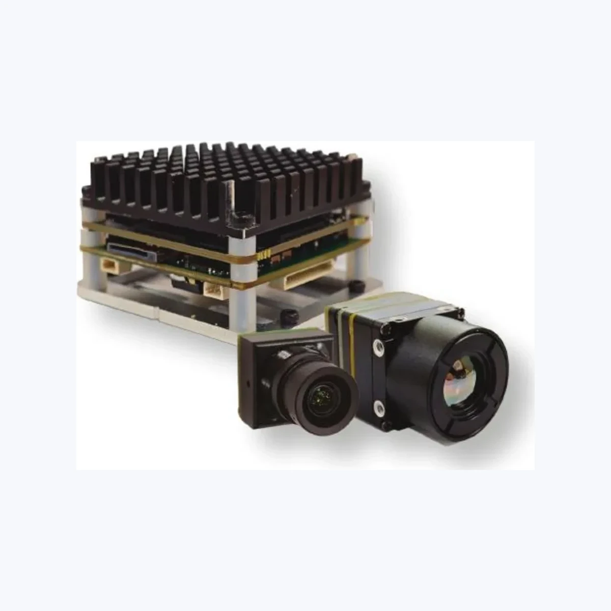
The TM02-SOLO T is an edge-AI vision core engineered specifically for UAV builders and robotic platforms that need rock-solid target tracking across direct sunlight, absolute darkness, and low-contrast thermal scenes. Pairing an onboard 6 TOPS NPU with a 640×512 uncooled VOx thermal sensor and a high-speed 1080p visible camera running at 120 Hz, it delivers real-time target locking on subjects moving at relative speeds up to 450 km/h.
| TM02-SOLO T Comprehensive Technical Specifications | |
|---|---|
| AI Processing & Tracking Engine | |
| AI Edge Compute | 6 TOPS Dedicated Neural Processing Unit |
| Application CPU | Arm Cortex-A76 @ 2.4 GHz + Cortex-A55 @ 1.8 GHz |
| Target Classification | Person and Vehicle detection, classification, and locking |
| Detection Distance | Vehicle: 400 m; Person: 170 m (Supplier baseline) |
| Min Target Resolution | 10 x 10 pixels minimum bounding box size |
| Processing Latency | 8 ms supplier table reference |
| Target Dynamic Speed | Up to 450 km/h tracking capability |
| Advanced Modes | Reticle locking, close-to-lock, route pre-map, lost-target recall, PIP |
| Simultaneous Tracks | Up to 120 target tracks (model and firmware dependent) |
| Thermal Camera (LWIR) Subsystem | |
| Detector Type | Uncooled Vanadium Oxide (VOx) Microbolometer |
| Thermal Resolution | 640 x 512 pixels @ 50 Hz native frame rate |
| Spectral Band & Pitch | 8 to 14 µm (LWIR); 12 µm pixel pitch |
| Focal Length & FOV | 9.1 mm; FOV: Diagonal 61.8°, Horizontal 47.7°, Vertical 38.2° |
| Board Interface | Direct MIPI supplier reference |
| Electro-Optical Visible (EO) Subsystem | |
| Optical Sensor & Lux | 1/1.8-inch CMOS; 0.001 lux starlight sensitivity |
| Resolution & Rate | 1920 x 1080 (1080p) @ 120 Hz |
| Lens Optics & FOV | 8.45 mm focal length; FOV: D 66.3°, H 57.1°, V 30.4° |
| EO Physical Size | 25.5 x 19.5 x 19.5 mm |
| Electrical, Mechanical & Integration | |
| Flight Controllers | BetaFlight, ArduPilot (CRSF Protocol) |
| Operating Power | Regulated 9 V to 16 V DC input |
| Board Dimensions | 45 x 45 x 26 mm (Mounting pattern: 42.5 x 42.5 mm) |
View Product Details & Pricing ➔
Product Model: TC01-DUAL Compact Dual-Spectrum UAV AI Tracking Module
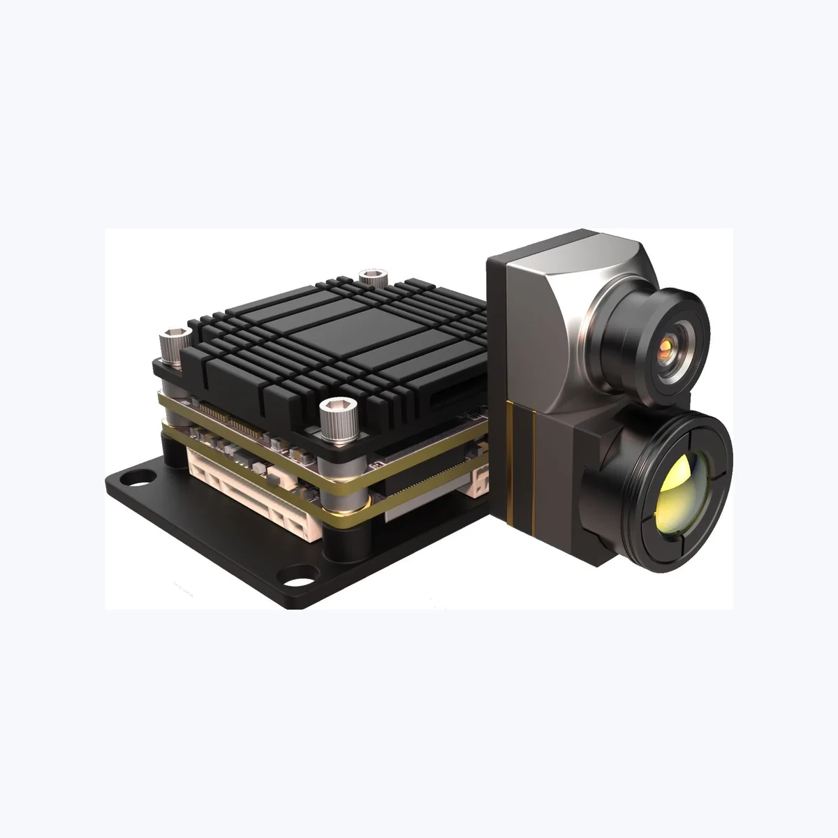
The TC01-DUAL delivers a stripped-down, ultra-compact footprint engineered for tightly packaged drone frames, compact ground crawlers, and fixed perimeter sentry nodes. Housing 4 TOPS of neural compute, an ultra-wide 109° horizontal FOV visible camera, and a 640×512 uncooled thermal core on a 38 x 38 mm board layout, it provides instant dual-light fusion and real-time target identification without chewing up your payload weight budget.
| TC01-DUAL Comprehensive Technical Specifications | |
|---|---|
| AI Processing & Tracking Engine | |
| AI Edge Compute | 4 TOPS Dedicated Edge Neural Network Unit |
| Target Classification | Person and Vehicle auto-identification & locking |
| Detection Distance | Vehicle: 800 m; Person: 300 m (Supplier baseline) |
| Min Target Resolution | 10 x 10 pixels minimum bounding box size |
| Tracking Latency | 30 ms reference latency |
| Dynamic Target Speed | Up to 140 km/h dynamic tracking speed |
| Simultaneous Targets | Up to 60 identified targets simultaneously |
| Display & Fusion | Picture-in-Picture (PIP) and dual-light fusion supported |
| Thermal Camera (LWIR) Subsystem | |
| Detector Class | Uncooled LWIR Thermal Imaging Camera |
| Thermal Resolution | 640 x 512 pixels @ 50 Hz native frame rate |
| Spectral Band & Pitch | 8 to 14 µm (LWIR); 12 µm pixel pitch |
| Focal Length & FOV | 9.1 mm; FOV: Diagonal 61.8°, Horizontal 47.7°, Vertical 38.2° |
| Camera Body Size | 29.49 x 19.1 x 19.1 mm (USB connection reference) |
| Electro-Optical Visible (EO) Subsystem | |
| Optical Sensor & Lux | 1/1.8-inch CMOS; 0.001 lux starlight sensitivity |
| Resolution & Rate | 2160 x 1440 @ 60 Hz |
| Lens Optics & FOV | 4.37 mm ultra-wide lens; FOV: D 131.6°, H 109°, V 57.5° |
| EO Physical Size | 25.5 x 19.5 x 19.5 mm |
| Electrical, Mechanical & Integration | |
| Flight Controllers | BetaFlight, ArduPilot (CRSF Protocol) |
| Operating Power | Regulated 9 V to 16 V DC input |
| Board Dimensions | 38 x 38 x 24.5 mm (Mounting pattern: 25.5 x 25.5 mm) |
View Product Details & Pricing ➔
For more architectural breakdowns, field benchmarks, and system schematics, dive into our complete embedded vision technical knowledge base.
5. SWaP-C Optimization: Balancing Compute, Optics, and Sensor Pitch
In aerospace and mobile robotics, every engineering decision is chained to SWaP-C: Size, Weight, Power, Cost, and Cooling. Dialing in a thermal imaging payload means understanding exactly how microbolometer detector pitch directly drives your optics costs and overall battery runtimes.
The single biggest factor driving thermal payload expense is the physical pixel pitch of the microbolometer. The Instantaneous Field of View (IFOV)—which sets the spatial resolution your system sees at a specific operating distance—is governed by a simple optical ratio:
IFOV = Pixel Pitch (p) / Focal Length (f)
Upgrading from legacy 17 µm microbolometer arrays to modern 12 µm detectors (like those built into the TM02-SOLO T and TC01-DUAL) delivers immediate weight and cost wins. Because the individual detector pixels are physically smaller, a 12 µm array needs a significantly shorter focal length lens to hit the exact same angular resolution and Johnson’s Criteria detection range as an older 17 µm sensor.
In the shop, this translates directly to dollars and grams. Monocrystalline Germanium is an expensive, heavy optical crystal, and raw material costs climb cubically with lens clear aperture diameter. By shortening your required focal length, you shrink the required lens diameter. That means a 12 µm optical stack is substantially lighter, far more compact, and cheaper to machine than a 17 µm equivalent—lowering your structural BOM while making gimbal balancing much easier on compact airframes.
On top of the glass savings, modern dual-spectrum modules eliminate mechanical failure points through onboard neural compute. Older systems had to rely on heavy motorized zoom mechanisms and large multi-axis gimbals to bring distant targets into focus. Those mechanical zoom assemblies burn 10 to 20 Watts of continuous battery power, add dead weight, and constantly fail under hard flight vibration and high-G maneuvers.
By pairing fixed, ruggedized Germanium optics with 4 to 6 TOPS of onboard neural processing, you can replace heavy mechanical zoom gimbals with real-time edge processing. Trained deep-learning models can reliably lock onto targets showing as few as 10×10 pixels in the frame, running electronic image stabilization (EIS), Picture-in-Picture sensor fusion, and predictive trajectory tracking at native line rates without burning extra battery or adding mechanical weak spots.
6. Flight Controller & Protocol Integration: ArduPilot, BetaFlight, and CRSF
Dropping an OEM dual-spectrum camera core into an airframe or ground vehicle takes two things: clean, isolated power routing and deterministic, low-latency telemetry piping into your autopilot stack.
Let’s talk power first. Edge NPUs running continuous neural inference alongside 50 Hz microbolometer readout electronics draw dynamic, switching current spikes. You cannot run these modules off shared dirty lines. Power the core through a dedicated, low-ripple, regulated 9 V to 16 V DC buck-boost supply. To keep brushless motor switching spikes from showing up as lines across your thermal frame, solder low-ESR solid electrolytic filter capacitors right on the input rail and wire a clean, single-point star ground connecting the camera module, flight controller, and digital Video Transmitter (VTX).
For autopilot telemetry and tracking control, the TM02-SOLO T and TC01-DUAL use native Crossfire (CRSF) protocol and direct serial UART communication. This gives you instant integration with standard ArduPilot and BetaFlight autopilot environments without having to write custom serial parsers from scratch.
Wiring is straightforward: run the module’s hardware UART TX and RX lines directly to an open serial port on your flight controller. Inside your ground control station or autopilot configurator, map your discrete RC auxiliary switches to handle core operations:
- ⚙️ Tracking Mode Selection (e.g., RC Aux Channel 7): Switch dynamically between Manual Optical Pass-Through, Center Reticle Lock, and Automated Route Pre-Map / Lost-Target Recall.
- ⚙️ Sensor Fusion Mode (e.g., RC Aux Channel 8): Toggle the live feed between Daylight Visible full-screen, 640×512 LWIR Thermal full-screen, Picture-in-Picture (PIP), and Dual-Spectrum Edge Fusion.
- ⚙️ Target Acquisition Trigger (e.g., RC Aux Channel 9): Instant one-click target lock handoff, reticle centering, or immediate tracking disengagement.
When the onboard NPU locks onto a target, its internal tracking engine calculates the spatial deviation angles ($\Delta \theta_x, \Delta \theta_y$) relative to your optical boresight. The module streams these offset vectors directly into the autopilot flight loop over compact CRSF packets. Your flight controller reads those offsets and executes automated yaw and pitch corrections to keep the airframe or gimbal centered on the target, completely hands-off.
7. Step-by-Step B2B Procurement and Flight Validation Checklist
To keep your integration timeline on schedule and avoid costly board redesigns, run your engineering team through this structured phase-by-phase validation checklist from initial quote to flight clearance.
Phase 1: RFQ and Interface Specification Verification
- ⚙️ Mechanical Pinout Confirmation: Lock down exact PCB hardware revisions, connector polarities, mating FPC/ribbon part numbers, and mounting hole pitch before cutting chassis metal.
- ⚙️ Optical FOV Matching: Verify the thermal horizontal FOV (e.g., 47.7°) and visible FOV (e.g., 57.1° or 109°) match your target Ground Sampling Distance (GSD) at operating altitudes.
- ⚙️ Tracking Firmware Profile: Verify the pre-flashed neural network weights match your operational mission profile (person, maritime asset, or vehicle tracking).
Phase 2: Bench Integration and EMI Characterization
- ⚙️ Power Rail Ripple Validation: Put an oscilloscope on the regulated 9–16 V DC rail to confirm less than 50 mV peak-to-peak switching ripple while running full NPU compute load.
- ⚙️ RF EMI Characterization: Scan RF noise floors around your GPS/GNSS receiver antennas to ensure high-frequency ARM and NPU clocks don’t desense satellite constellation locks.
- ⚙️ Protocol Telemetry Loop: Bench-test bidirectional CRSF and UART communication with your flight controller, verifying target lock flags populate on the Ground Control Station (GCS) map.
Phase 3: Thermal Stress and NUC Calibration Testing
- ⚙️ Chamber Soak Profile: Soak the integrated assembly across the operational temperature range (-10°C to +50°C) to verify that onboard Non-Uniformity Correction (NUC) tables eliminate thermal drift.
- ⚙️ Shutter Timing Validation: Confirm that periodic internal mechanical shutter cycles don’t cause tracking dropouts or freeze autopilot tracking loops during flight maneuvers.
Phase 4: Dynamic Flight Certification
- ✅ Vibration Isolation Verification: Run high-throttle flight sweeps while checking the thermal stream for rolling-shutter artifacts or microbolometer physical resonance.
- ✅ Dynamic Range Field Trials: Verify vehicle tracking ranges (400 m to 800 m) and evaluate re-acquisition performance during target occlusions and tree cover pass-throughs.
8. Frequently Asked Questions (FAQ)
What is the primary difference between a cheap infrared camera and an OEM thermal core?
Why do consumer thermal smartphone dongles fail in UAV and robotic tracking applications?
How does microbolometer pixel pitch affect the overall system bill of materials (BOM)?
Can the thermal channel on dual-spectrum tracking modules be used for radiometric temperature measurement?
📚 References & Further Reading
- Industry Standard: Explore commercial drone vision developments and sensor integration standards via Commercial UAV News.
- Industry Standard: Review commercial microbolometer manufacturing benchmarks and thermal sensor trends via Hikmicro.
- Related Guide: Consult our in-depth engineering blueprint: Infrared Camera Module OEM Buying Guide.