Thermal Imaging Drones: OEM Guide to Low-SWaP 640×512 LWIR Integration
Thermal Imaging Drones: OEM Guide to Low-SWaP 640×512 LWIR Integration
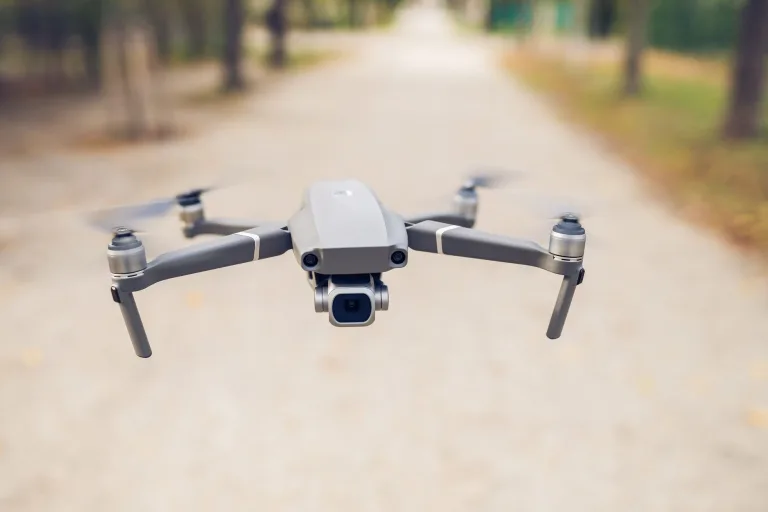
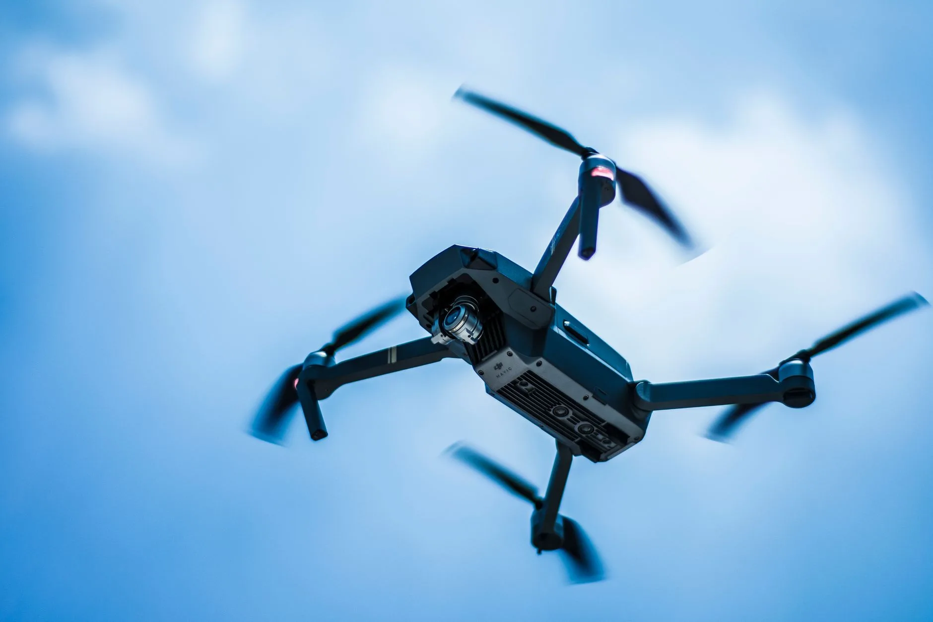
Modern airborne surveillance, tactical reconnaissance, industrial inspection, and search-and-rescue (SAR) operations have pushed unmanned aerial systems to their physical limits. High spatial resolution and crisp thermal sensitivity are no longer luxuries reserved for heavy, high-altitude military platforms. Integrating uncooled Long-Wave Infrared (LWIR) camera cores into modern thermal imaging drones—spanning sub-250 g micro-unmanned aerial vehicles (micro-UAVs), tactical First-Person View (FPV) loitering munitions, and commercial multi-rotor inspection birds—demands a no-nonsense balance between optical aperture sizing, sensor pixel pitch, video pipeline latency, and thermal dissipation management.
Here’s the deal: as drone airframes get lighter and micro-gimbals shrink toward sub-50 g total envelopes, payload engineers hit brutal hardware tradeoffs. Choosing between ultra-miniature 8 μm and field-proven 12 μm Vanadium Oxide (VOx) focal plane arrays (FPAs) directly dictates the physical mass of front-element Germanium optics. At the same time, matching host interface architectures to either low-latency 50/60 Hz analog and raw digital streaming (for high-speed flight navigation) or 25/30 Hz calibrated radiometric temperature data paths (for predictive utility inspection) represents the core engineering hurdle in payload design.
In the shop, we see teams struggle with the same pitfalls: noisy power rails from dirty ESC switching, thermal throttling inside sealed gimbals, and lenses that lose focus the second the drone climbs a few hundred meters. This comprehensive OEM engineering guide delivers a practical integration blueprint for embedding 640×512 LWIR thermal modules into next-generation aerial platforms, covering electrical interfaces, optical target acquisition math (DRI), mechanical stabilization, and production-ready hardware architectures.
Table of Contents
- 👉 1. The SWaP Revolution in Drone Thermal Imaging: 8 μm vs. 12 μm Architecture
- 👉 2. Mission Profiling: Qualitative Night Vision vs. Radiometric Thermography
- 👉 3. Electrical, Power, and Video Pipeline Architecture for UAV Micro-Gimbals
- 👉 4. Optical Engineering: Athermal Lenses, FOV, and IFOV Target Calculations
- 👉 5. OEM Product Showcase & Technical Matrix: Ultra-Light 640×512 Modules
- 👉 6. Mechanical Stabilization, Thermal Dissipation, and Flight Acceptance
- 👉 7. Deep-Dive OEM Integration FAQ
1. The SWaP Revolution in Drone Thermal Imaging: 8 μm vs. 12 μm Architecture
The optical physics governing an airborne thermal imaging camera establish a hard reality: the physical volume and mass of an infrared imaging payload are dictated primarily by detector size. For decades, uncooled LWIR microbolometers relied on chunky 17 μm and 12 μm pixel pitch structures. While 12 μm detectors remain reliable workhorses across mid-to-large enterprise airframes, the arrival of 8 μm Vanadium Oxide (VOx) focal plane arrays has completely rewritten the low-SWaP (Size, Weight, and Power) playbook for aerial systems.
When you break down this transition on the mechanical CAD bench, the downstream benefits multiply fast:
- ✅ Aperture and Optical Glass Mass Reduction: A standard 640×512 array on a 12 μm pitch produces an active sensor diagonal of roughly 9.83 mm. Scaling that exact same 640×512 resolution down to an 8 μm pixel pitch shrinks the active sensor diagonal to just 6.55 mm—that is a 33% reduction in linear dimensions and a massive 55% reduction in total active focal plane area. Because lens focal length scales linearly with detector dimensions to achieve a targeted Field of View (FOV), 8 μm systems require significantly shorter focal lengths. Shorter focal lengths directly yield smaller clear optical apertures at equivalent f-numbers ($f/1.0$), slashing expensive Germanium or Chalcogenide glass mass by over 50% to 65%.
- ✅ Gimbal Motor Sizing and Dynamic Balancing: Micro-gimbals engineered for tactical FPVs and sub-250 g category drones face unforgiving payload inertia budgets. Swapping out a legacy 20–40 g thermal core assembly for an ultra-compact bare core weighing under 3.5 g—such as the CAMCUDA SuperMini 640—cuts angular momentum by nearly an order of magnitude. This dramatic reduction lets mechanical engineers drop down to smaller, lighter brushless gimbal motors (like 1104 to 1404 stator sizes) driven by lower PID currents, directly preserving battery reserves and adding precious minutes to mission endurance.
- ✅ Diffraction Limits vs. Advanced Signal Processing: At long-wave infrared wavelengths (8–14 μm), an 8 μm pixel pitch runs right up against the theoretical optical diffraction limit ($\lambda \approx 10\ \mu\text{m}$). However, modern thin-film VOx microbolometer wafer processing, coupled with low-noise readout integrated circuits (ROIC) and proprietary spatial noise filtering algorithms, keeps thermal sensitivity razor-sharp. Uncooled 8 μm and 12 μm cores hit Noise Equivalent Temperature Differences (NETD) of $\le 40\text{ mK}$ and $\le 30\text{ mK}$ at $f/1.0$, respectively, delivering exceptional thermal gradient contrast even through zero-illumination, low-delta night flight conditions.
For drone payload builders developing dual-sensor Electro-Optical/Infrared (EO/IR) pods, ditching heavy legacy cores for miniaturized 8 μm or compact 12 μm engines frees up critical mass and spatial volume. That saved budget can go right into continuous-zoom daylight optics, laser rangefinders, or onboard edge-AI compute boards without compromising flight dynamics.
2. Mission Profiling: Qualitative Night Vision vs. Radiometric Thermography
Before you pick a camera core and lock down your PCB schematics, you have to nail down the primary flight mission: does the drone need high-speed qualitative situational vision, or quantitative, calibrated surface temperature measurement?
Qualitative Situational Awareness (50 Hz / 60 Hz Imaging)
For low-altitude FPV navigation, perimeter defense, tactical ISR (Intelligence, Surveillance, and Reconnaissance), and rapid Search and Rescue (SAR), raw frame rate and dynamic visual contrast take priority over absolute temperature readouts. Thermal cores built for qualitative imaging output continuous 8-bit visual streams at 50 Hz or 60 Hz over low-latency analog CVBS, 8-bit LVCMOS (BT.656), or 2-lane MIPI CSI-2 interfaces.
These modules utilize dedicated image signal processing (ISP) pipelines that apply dynamic Automatic Gain Control (AGC), high-order Digital Detail Enhancement (DDE), and adaptive histogram equalization. These algorithms compress the microbolometer’s raw 14-bit dynamic range into an 8-bit display format tuned for the human eye or edge machine-vision classifiers, making subtle thermal gradients stand out clearly between human targets, warm engine blocks, and cold background terrain.
Radiometric Thermography (25 Hz / 30 Hz Calibrated Data)
Industrial drone inspections—such as high-voltage transmission line audits, utility-scale solar PV hotspot mapping, structural envelope diagnostics, and agricultural crop-stress analysis—demand calibrated radiometric temperature values. Radiometric modules output linear, high-bit-depth raw thermal data (typically 14-bit or 16-bit digital frames via CDS3, YUV raw, or MIPI) where every single pixel directly corresponds to a real-world temperature point.
These pipelines run at 25 Hz or 30 Hz because of the heavy computational overhead required for per-pixel non-uniformity correction (NUC), internal shutter drift compensation, and temperature look-up calculations across wide industrial spans (e.g., $-20^\circ\text{C}\text{ to }+150^\circ\text{C}$ and $100^\circ\text{C}\text{ to }+650^\circ\text{C}$). To get accurate temperature readings in the air, companion software and ground stations have to factor in target emissivity, ambient atmospheric temperature, flight altitude, and relative humidity. When designing custom analytical software, systems architects frequently benchmark calibration behaviors against known thermal inspection tools, as detailed in our Thermal Master P1 review and OEM limitations analysis, to ensure baseline drift stability before mounting payloads to the airframe.
3. Electrical, Power, and Video Pipeline Architecture for UAV Micro-Gimbals
Mounting an uncooled thermal camera core inside a UAV micro-gimbal requires clean power regulation, low-latency video routing, and aggressive EMI shielding. Drones are notoriously hostile electrical environments where high-current Electronic Speed Controllers (ESCs) and Brushless DC (BLDC) motors dump massive voltage spikes and high-frequency switching noise across the main power distribution board.
Power Rail Regulation and Low-Noise Power Design
Uncooled VOx microbolometers work by detecting microscopic resistance changes across micro-machined bridge structures caused by incoming infrared energy. Consequently, any voltage ripple or electrical noise riding on the core’s internal analog bias rails directly creates horizontal banding, fixed-pattern noise (FPN), or severe calibration drift across the image.
- ⚙️ Main Input Voltage: Primary module supply feeds typically demand a regulated $3.8\text{ V to }5.2\text{ V}$ (nominal 5.0 V) supply. This rail must be filtered to keep peak-to-peak noise strictly under $10\text{ mV p-p}$. Tapping directly into unregulated battery lines (like 4S or 6S LiPo packs) will instantly toast the core’s input stage.
- ⚙️ Sub-Regulated Core Feeds: Cores exposing separate $+3.3\text{ V}$ and $+1.8\text{ V}$ logic rails require razor-thin voltage tolerances (e.g., $3.28\text{–}3.32\text{ V}$ and $1.78\text{–}1.82\text{ V}$). The $+1.8\text{ V}$ analog-adjacent rail demands an ultra-quiet noise floor ($\le 1\text{ mV RMS}$ from 1 Hz to 50 kHz), meaning you need dedicated Low-Dropout (LDO) linear regulators placed right next to the gimbal slip ring or camera connector.
- ⚙️ Ground Isolation and Return Paths: Digital return ground planes for MIPI/UART buses must be isolated from heavy motor return paths using ferrite beads and a clean star-grounding architecture to prevent frame drops and data corruption.
Video Pipelines and Flight Controller Integration
Look at your companion processing setup onboard the UAV to select the proper video pipeline:
- ⚙️ Digital Video (MIPI CSI-2 & BT.656): For builds running onboard companion computers (like the NVIDIA Jetson Orin Nano, Rockchip RK3588, or Raspberry Pi CM4), uncompressed digital video over 2-lane MIPI CSI-2 or 8-bit LVCMOS (BT.656 for qualitative video; CDS3 for radiometric data) gives you zero added latency and preserves raw 14-bit data for real-time edge AI object tracking and analytics.
- ⚙️ Analog Video (CVBS): For ultra-compact tactical FPV airframes and standard analog downlinks, analog composite video (CVBS, PAL/NTSC) provides zero-latency pilot feedback straight into 5.8 GHz video transmitters (VTX). Note that certain ultra-miniature bare cores require a tiny external video buffer IC on the carrier board to drive a standard $75\ \Omega$ coaxial load.
- ⚙️ USB Interfacing: Carrier expansion boards (such as the TMS6102V100F022) convert the core’s native high-density connector signals into standard USB 2.0 (UVC/V4L2) streams, making bench testing and companion computer integration plug-and-play across Windows, Linux, and Android environments.
- ⚙️ Command & Control Bus: Bi-directional serial communication (UART with 1.8 V or 3.3 V logic levels; or RS232/RS422 on industrial boards) handles telemetry, electronic shutter triggering for Non-Uniformity Correction (NUC), color palette cycling (White Hot, Black Hot, Rainbow, Ironbow), digital zoom steps ($1\times\text{ to }8\times$), and temperature query commands.
High-density board-to-board connectors—such as the 30-pin Hirose DF40C-30DP-0.4V(51) (0.4 mm pin pitch)—pack the entire power, digital video, serial control, and analog video bus into a footprint smaller than a fingernail.
4. Optical Engineering: Athermal Lenses, FOV, and IFOV Target Calculations
Selecting the right optics for a thermal drone means balancing area coverage (Field of View) against standoff distance. In aerial thermal mission planning, optical performance comes down to Instantaneous Field of View (IFOV) and target resolution requirements defined by Johnson’s Criteria for Detection, Recognition, and Identification (DRI).
Optical Calculations and Formulas
The geometric resolution of a thermal payload is defined by these core equations:
$$\text{IFOV (mrad)} = \frac{\text{Pixel Pitch } (\mu\text{m})}{\text{Focal Length } (f\text{ in mm})}$$
$$\text{Ground Resolved Distance (GRD)} = \text{IFOV (mrad)} \times \text{Altitude Above Ground Level (AGL in meters)}$$
$$\text{Detection Range (m)} = \frac{\text{Target Dimension (m)}}{\text{Required Pixels on Target}} \times \frac{f\text{ (mm)}}{\text{Pixel Pitch } (\mu\text{m}) \times 10^{-3}}$$
| Lens Focal Length | Core Pitch | Aperture (F-No.) | IFOV (mrad) | Field of View (H × V) | Primary UAV Application |
|---|---|---|---|---|---|
| 3.7 mm (SuperMini) | 8 μm | F1.0 | 2.16 mrad | 90.0° × 68.2° | Ultra-wide situational awareness, obstacle avoidance, close FPV flight |
| 6.1 mm (SuperMini) | 8 μm | F1.0 | 1.31 mrad | 46.6° × 37.6° | Balanced tactical FPV, general night search, sub-250g payload |
| 8.7 mm (SuperMini) | 8 μm | F1.0 | 0.92 mrad | 40.0° × 32.2° | Medium-range perimeter patrol, rooftop solar inspection |
| 11.0 mm (SuperMini) | 8 μm | F1.0 | 0.73 mrad | 24.9° × 20.0° | Extended stand-off target tracking, industrial utility auditing |
| 9.0 mm (AeroMini) | 12 μm | F1.0 | 1.33 mrad | 48.7° × 38.6° | General enterprise UAV mapping, daylight/thermal pod pairing |
| 18.0 mm (AeroMini) | 12 μm | F1.0 | 0.67 mrad | 24.2° × 19.5° | Long-range human detection, power grid transmission tower audit |
| 35.0 mm (AeroMini) | 12 μm | F1.0 | 0.34 mrad | 12.5° × 10.0° | High-altitude tactical standoff, border surveillance |
Optical Athermalization for Aerial Environments
Drones deal with violent ambient temperature swings—baking at $+35^\circ\text{C}$ on an asphalt launch pad and plunging below $-10^\circ\text{C}$ within minutes after climbing past 1,000 meters AGL. Standard Germanium optical elements have a massive thermal refractive index coefficient ($dn/dt \approx 400 \times 10^{-6}/\text{K}$ at $10.6\ \mu\text{m}$). Without mechanical compensation, that temperature drop throws the optical assembly out of focus, collapsing your Modulation Transfer Function (MTF).
To avoid manual focus adjustments during flight, drone integration requires F1.0 athermalized lens assemblies. These lenses utilize mechanical barrels built with dissimilar metals (like aluminum and Delrin/Invar sleeves) whose differing thermal expansion rates precisely counteract the optical shift of the Germanium elements across $-40^\circ\text{C}\text{ to }+80^\circ\text{C}$.
5. OEM Product Showcase & Technical Matrix: Ultra-Light 640×512 Modules
Modern thermal camera cores optimized for UAV payloads combine ultra-compact form factors, minimal power consumption, and flexible interface options. Below are two industry-standard LWIR OEM solutions purpose-built for micro-gimbals and enterprise drone payloads.
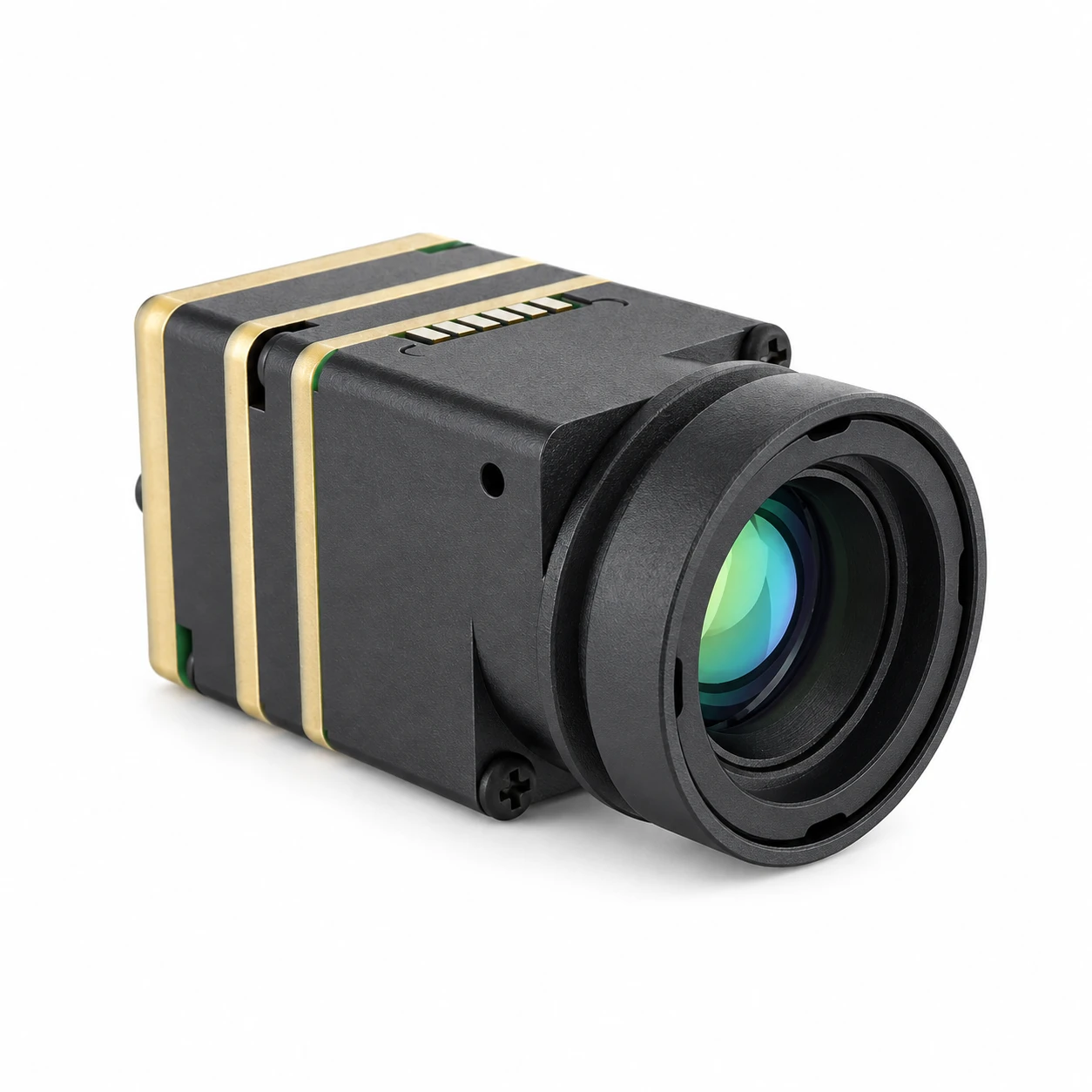
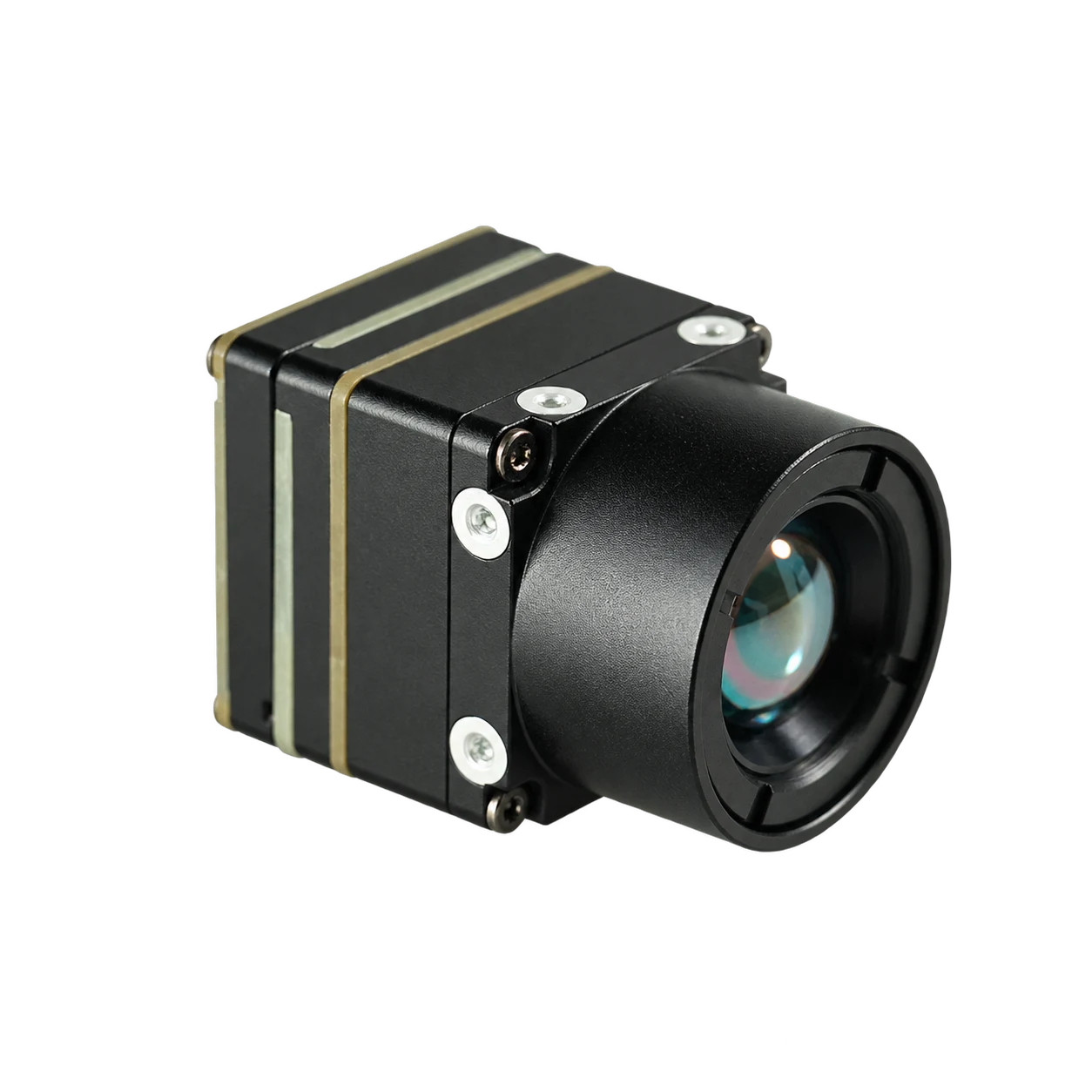
CAMCUDA SuperMini 640 / 640T Ultra-Light LWIR Thermal Camera Module
The CAMCUDA SuperMini 640 / 640T sets an industry benchmark for low-SWaP airborne integration, combining a 640×512 uncooled VOx focal plane array, an 8 μm pixel pitch, and an ultra-compact 13 × 13 × 13.4 mm envelope in a core weighing less than 3.5 g. Engineered specifically for micro-gimbals, sub-250g UAVs, tactical FPV platforms, and embedded thermal imaging payloads, the series consumes $\le 0.5\text{ W}$ typical core power.
- Resolution & Pitch: 640 × 512, 8 μm uncooled VOx microbolometer
- Bare Core SWaP: 13 × 13 × 13.4 mm footprint, <3.5 g core weight, ≤0.5 W power
- Dual Factory Models: SuperMini 640 (50 Hz imaging-only) & SuperMini 640T (30 Hz radiometric, −20°C to +650°C)
- Sensitivity: NETD ≤40 mK @ 25°C, F1.0
- Interface: Hirose DF40C-30DP-0.4V(51) 30-pin connector with 2-lane MIPI, 8-bit LVCMOS (BT656/CDS3), 1.8V UART, USB 2.0, CVBS
- Lenses: 3.7 mm (90.0°), 6.1 mm (46.6°), 8.7 mm (40.0°), 11 mm (24.9°) F1.0 athermal
CAMCUDA AeroMini 640×512 Uncooled LWIR Thermal Camera Core
The CAMCUDA AeroMini 640 delivers exceptional thermal sensitivity and extended optical reach for mid-sized enterprise UAVs, industrial inspection gimbals, and dual-sensor pods. Built on a 12 μm VOx detector format with a 21 × 21 × 28 mm chassis weighing under 20 g (without lens), it provides high sensitivity (NETD $\le 30\text{ mK}$) and versatile output options across analog, USB, and digital bus architectures.
- Resolution & Pitch: 640 × 512, 12 μm uncooled VOx detector
- High Sensitivity: NETD ≤30 mK at 25°C, F1.0 for high thermal gradient detection
- Frame Rate Options: Non-radiometric 60 Hz default (30 Hz optional); Radiometric 25 Hz (−20°C to +550°C)
- Core Envelope: 21 × 21 × 28 mm, <20 g core weight, <0.5 W typical core power
- Flexible I/O: YUV, USB, BT.656 digital; CVBS (PAL/NTSC) analog; UART/RS232/RS422 serial
- Broad Lens Catalog: 4 mm, 7 mm, 9 mm, 13 mm, 15 mm, 18 mm, 25 mm, 35 mm, 50 mm, 60 mm
Comprehensive Engineering Specification Matrix
The engineering matrix below directly compares both OEM camera cores across mechanical, electrical, thermal, and optical integration boundaries:
| Integration Parameter | CAMCUDA SuperMini 640 / 640T | CAMCUDA AeroMini 640 |
|---|---|---|
| Detector Architecture | Uncooled VOx Focal Plane Array | Uncooled VOx Focal Plane Array |
| Array Resolution | 640 × 512 | 640 × 512 |
| Pixel Pitch | 8 μm (Ultra-low glass mass) | 12 μm (Extended optical stand-off) |
| Thermal Sensitivity (NETD) | ≤ 40 mK @ 25°C, F1.0 | ≤ 30 mK @ 25°C, F1.0 |
| Core Dimensions (W × H × D) | 13 × 13 × 13.4 mm (Bare core) | 21 × 21 × 28 mm (Bare core) |
| Bare Core Weight | < 3.5 g | < 20 g |
| Typical Power Consumption | ≤ 0.5 W (Typical at 25°C) | < 0.5 W (Module typical) |
| Spectral Response | 8 – 14 μm (LWIR) | 8 – 14 μm (LWIR) |
| Frame Rates & Variants | 640: 50 Hz (Imaging) 640T: 30 Hz (Radiometric) |
Non-Rad: 60 Hz default / 30 Hz Radiometric: 25 Hz |
| Thermography Range | 640T: −20°C to +150°C & 100°C to +650°C | Radiometric: −20°C to +550°C |
| Digital Output Protocols | 2-Lane MIPI, 8-bit LVCMOS (BT656/CDS3) | YUV, USB, BT.656 (Board-dependent) |
| Analog Video Output | CVBS pin (Requires external buffer IC) | CVBS, PAL, NTSC (Board-dependent) |
| Electrical Connector | Hirose DF40C-30DP-0.4V(51) 30-Pin | Hirose / Flex Ribbon / USB Board Options |
| Supply Input Requirements | 3.8–5.2 V (5V typ, ≤10 mV p-p noise) +3.3V (10mV noise), +1.8V (1mV RMS) |
5.0 V or 12.0 V (Board-dependent; POWER_IN pins are 5V strictly) |
| Standard Lens Options | 3.7 mm, 6.1 mm, 8.7 mm, 11 mm | 4 mm, 7 mm, 9 mm, 13 mm, 15 mm, 18 mm, 25 mm, 35 mm, 50 mm, 60 mm |
| Operating Temperature | −40°C to +80°C | −40°C to +80°C |
High-volume commercial wafer fabrication—accelerated by major detector producers like InfiRay—gives UAV payload engineers direct access to off-the-shelf thermal components that used to take six-month defense procurement cycles to acquire.
6. Mechanical Stabilization, Thermal Dissipation, and Flight Acceptance
Mounting sensitive microbolometer modules into aerial gimbals introduces high-frequency mechanical vibrations and thermal management headaches that directly impact image stability and radiometric calibration.
Conductive Thermal Pathing and Heat Dissipation
Even though uncooled cores draw very little power ($\le 0.5\text{ W}$), their miniature footprint ($13\times 13\text{ mm}$) produces high localized heat flux. In sealed, IP-rated gimbal pods without active cooling fans, that heat sits inside and warms the detector substrate. When internal chassis temperatures drift rapidly, the core’s NUC shutter has to drop frequently to recalibrate, causing annoying 500 ms video freezes that can break automated AI tracking locks during flight.
- ⚙️ Conductive Bridge Integration: Your gimbal housing must establish a direct conductive heat path from the camera core’s aluminum shell to the outer gimbal yoke. Use non-silicone thermal gap filler pads (thermal conductivity $\ge 3.0\text{ W/m}\cdot\text{K}$) compressed by 20–30% between the module housing and the gimbal frame.
- ⚙️ Convection Air Channeling: In fixed-wing noses or forward-facing camera pods, build micro-vent channels that route propeller wash or forward airspeed across the external heat-sink fins of the gimbal housing, keeping thermal equilibrium steady even while hovering on hot $+40^\circ\text{C}$ tarmac.
Vibration Isolation and Flight Demonstration Verification
Propulsion vibrations ($150\text{ Hz to }600\text{ Hz}$) cause mechanical microphonics across uncooled microbolometers, showing up on screen as horizontal ripple lines or visual blurring. Gimbals must use tuned silicone dampening balls calibrated to the payload mass to isolate the optical bench from airframe vibration harmonics.
Before ramping volume manufacturing, every integrated optical pod design has to go through formal flight acceptance testing to verify MTF sharpness, boresight alignment, and radiometric accuracy across real flight envelopes. Engineering teams should follow rigorous qualification protocols—like those outlined in our UAV thermal camera acceptance memo and demo flight guide—to thoroughly validate shutter stability under high-G turns, verify EMI immunity against high-power 2.4/5.8 GHz video links, and confirm focus retention across $-20^\circ\text{C}$ to $+60^\circ\text{C}$ thermal transitions.
7. Deep-Dive OEM Integration FAQ
Can I integrate a 640×512 thermal camera into a sub-250g drone or micro-gimbal?
What is the operational difference between qualitative thermal imaging and radiometric inspection on drones?
How do OEM engineers interface thermal camera cores with drone companion computers and video transmitters?
OEM Payload Integration Checklist
- ⚙️ Determine Spatial Target Resolution: Calculate required IFOV and lens focal length based on mission altitude (AGL) and DRI detection thresholds.
- ⚙️ Select Sensor Architecture: Choose 8 μm (SuperMini 640) for extreme low-SWaP/FPV and micro-gimbals; pick 12 μm (AeroMini 640) for extended stand-off distance and maximum thermal sensitivity.
- ⚙️ Validate Thermal & Video Pathways: Select qualitative 50/60 Hz BT.656/CVBS for flight piloting, or radiometric 25/30 Hz CDS3/MIPI for quantitative surface temperature inspection.
- ⚙️ Design Clean Power Rails: Ensure the primary 5.0 V supply holds $\le 10\text{ mV p-p}$ ripple and provide isolated LDO rails for sensitive 1.8 V bias lines.
- ⚙️ Implement Thermal Heat Sinking: Provide a direct conductive thermal gap pad bridge from the core chassis to the aluminum gimbal yoke to prevent thermal drift and shutter cycling in flight.
📚 References & Further Reading
- Industry Standard: Wikipedia – Thermal Imaging Camera Engineering Principles
- Sensors Technology: InfiRay Advanced Uncooled LWIR Detector Technologies
- Flight Acceptance: UAV Thermal Camera Acceptance Memo & Demo Flight Verification
- Hardware Diagnostics: Thermal Master P1 Review: Technical Specs, Limitations, and OEM Benchmarking
- Product Reference: CAMCUDA SuperMini 640 / 640T Ultra-Light LWIR Thermal Camera Module