Cheap Thermal Infrared Camera vs OEM Cores: Engineering Buyer’s Guide
Cheap Thermal Infrared Camera vs OEM Cores: Engineering Buyer’s Guide
Technical author: Daniel · Hardware Support
Every hardware engineer and procurement lead building an industrial machine vision rig, an autonomous mobile robot (AMR), a thermal drone payload, or a factory condition monitoring system hits the exact same fork in the road. On one side, you have a cheap thermal infrared camera sold as a handheld unit or smartphone dongle with illustrative budgets of $200 to $600. On the other side, bare OEM Long-Wave Infrared (LWIR) sensor cores and multi-spectrum edge-AI modules can cost several hundred to a few thousand dollars, depending on configuration. When project budgets get tight, someone in the room will inevitably ask: “Can’t we just buy a bunch of cheap consumer units, rip the plastic enclosures off, and hook them up to our embedded boards?”
Here’s the deal: on paper, that hack looks like an easy win to shave a few grand off your Bill of Materials (BOM). But once you get those budget units on the test bench, the engineering questions become more specific. Compare the actual detector resolution, frame rate, thermal sensitivity, calibration, and supported data access. Some inexpensive cameras prioritize a convenient handheld or phone workflow over embedded integration, while others offer useful development resources. A low purchase price alone does not tell you whether the camera will meet your system requirements.
If you try to drop a consumer thermal dongle into a 24/7 industrial inspection line, a closed-loop control setup, or an aerial observation gimbal, check thermal drift, frame timing, data access, and mechanical support before committing to a design. This guide breaks down the sensor physics and integration pipelines separating a finished consumer camera, an OEM thermal core, and an integrated AI camera module, covering hardware buses, optical selection, and total cost of ownership (TCO).
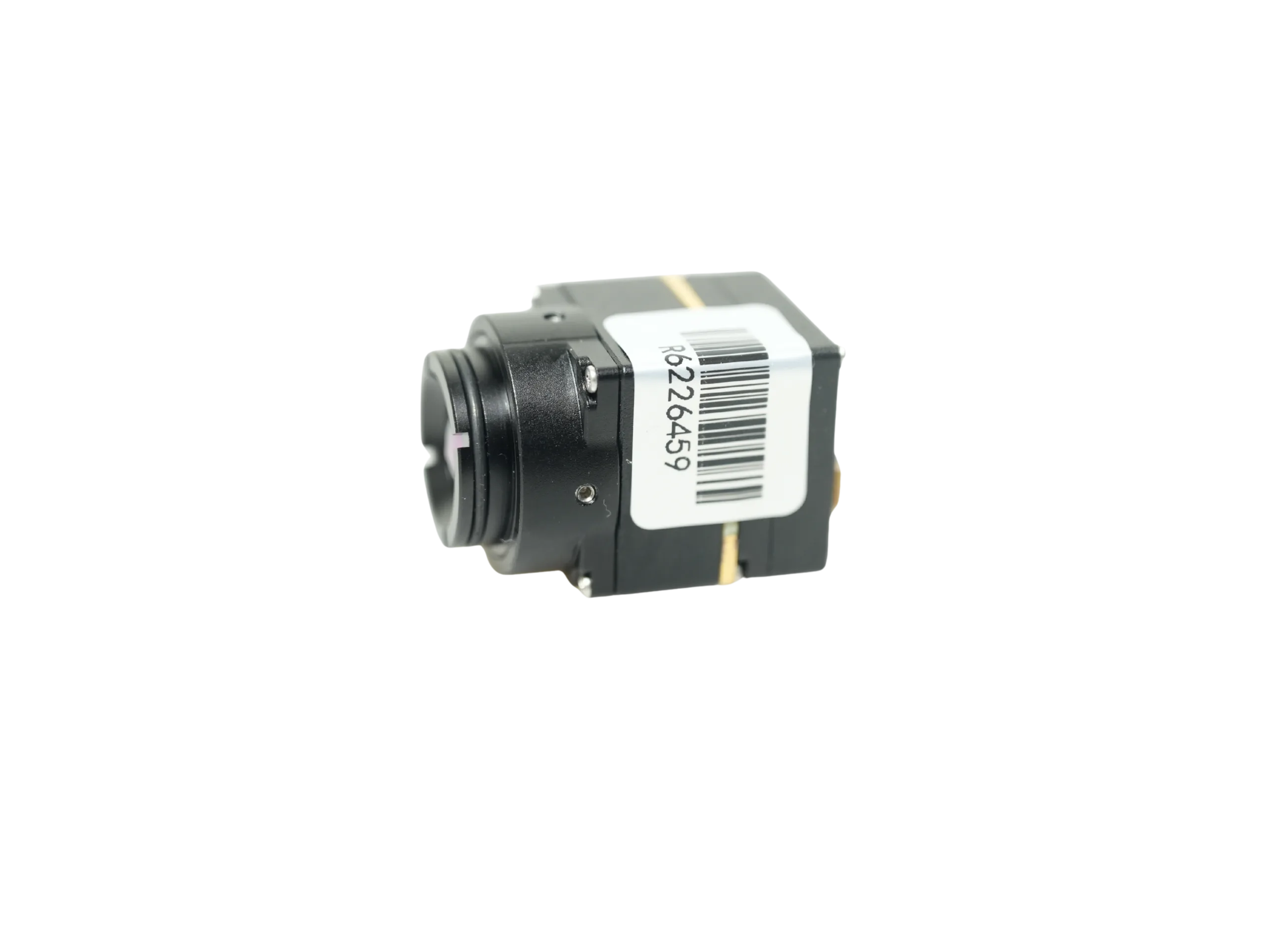
Table of Contents
- 👉 1. The Anatomy of “Cheap” Thermal Cameras: False Economies in Embedded Design
- 👉 2. Core Sensor Physics: Uncooled VOx FPAs vs. Low-Cost Thermopiles & Microbolometers
- 👉 3. Video Pipeline & Digital Interfaces: Consumer USB vs. MIPI CSI-2 & Industrial Streaming
- 👉 4. Edge AI & UAV Integration: Telemetry, SWaP-C, and Low-Latency Targeting
- 👉 5. Commercial OEM Thermal Modules: Technical Showcases & Specifications
- 👉 6. Bill of Materials (BOM) & TCO: Hidden Engineering Costs of Consumer Conversion
- 👉 7. Frequently Asked Questions (FAQ)
1. The Anatomy of “Cheap” Thermal Cameras: False Economies in Embedded Design
When you are designing an automated optical inspection (AOI) jig, an autonomous mobile robot, or a continuous monitoring node, a finished consumer imager may introduce integration constraints. Its enclosure, interfaces, and software support are often optimized for handheld use. Evaluate whether those choices fit the duty cycle and host architecture before treating the retail price as the complete cost.
What a Cheap Thermal Infrared Camera Must Support
The first trap is confusing display resolution with native detector resolution. A displayed 640×480 image may be scaled from a smaller thermal array or blended with a visible image. Upscaling can improve presentation, but it does not add independent thermal samples. For automated inspection, compare native array size, lens field of view, focus distance, and the number of pixels across the smallest feature you need to inspect. If you require temperature thresholds, separately confirm calibrated temperature data and its accuracy; neither a sharp display nor a high pixel count establishes that capability.
The second major roadblock is frame rate. A camera limited to about 9 Hz updates less frequently than a 30, 50, or 60 Hz configuration, which can matter for a moving conveyor, robotic arm, or UAV. Frame rate alone does not determine motion blur or end-to-end latency: detector response, integration time, buffering, transmission, and display all contribute. AeroMini 640 non-radiometric imaging defaults to 60 Hz, with a 30 Hz factory option; AI VisionCube DT Pro lists 50 Hz thermal output and 30 Hz visible output. Match the selected configuration to your motion and timing requirements.
Then comes thermal drift and Non-Uniformity Correction (NUC). Uncooled microbolometers respond to changes in sensor and ambient temperature. Cameras may use shutter-based or shutterless correction approaches; neither the price category nor the word OEM establishes which approach is supplied or how it behaves. Ask about warm-up, correction interruptions, drift, and calibration for the selected configuration, and test them over the intended temperature cycle. For a deeper look at long-wave cores in industrial environments, see our guide to uncooled LWIR thermal modules for outdoor security and industrial monitoring.
2. Core Sensor Physics: Uncooled VOx FPAs vs. Low-Cost Thermopiles & Microbolometers
To evaluate thermal camera hardware, look at detector resolution, thermal sensitivity, optics, and the required output data together. Noise Equivalent Temperature Difference (NETD), expressed in millikelvins (mK), describes thermal sensitivity under stated test conditions. Lower NETD can help distinguish small thermal differences, but it is not a temperature-accuracy specification.
AeroMini 640 uses an uncooled Vanadium Oxide (VOx) array and specifies NETD ≤30 mK at 25°C with F/1.0 optics. That figure does not promise absolute temperature accuracy of ±0.03°C, detection of a particular defect, or visibility through solid cover. Confirm whether the ordered module is an imaging or radiometric version before planning quantitative inspection.
VOx, amorphous-silicon microbolometers, and thermopile arrays appear in different camera designs. Do not infer the complete camera’s sensitivity, noise, or suitability from its detector material or price alone. Compare published specifications under equivalent conditions, then evaluate a sample using the target sizes, temperature differences, and working distances that matter to your application.
Pixel pitch is another critical parameter. Both AeroMini 640 and the thermal camera in AI VisionCube DT Pro list a 12 μm pitch and a 640×512 array. For a selected lens, the small-angle approximation below estimates the angular footprint of one detector pixel. Use the same length units for pixel pitch and focal length; the result is in radians:
IFOV ≈ Pixel Pitch (d) / Focal Length (f)
Lens focal length, aperture, transmission, focus distance, and detector pitch all affect image quality and spatial sampling. Do not assume every lens option uses the same material, F-number, or calibration. AeroMini 640 publishes model-specific lens/FOV options; the DT Pro thermal camera lists a 9.1 mm lens with 45.9° H × 36.9° V FOV. Use the thermal imaging calculator for preliminary optical planning, then validate the actual lens and scene. A geometric estimate is not a detection, recognition, or identification guarantee.
3. Video Pipeline & Digital Interfaces: Consumer USB vs. MIPI CSI-2 & Industrial Streaming
If you have ever tried hooking an external sensor up to an NVIDIA Jetson, Raspberry Pi CM4, NXP i.MX8, or custom FPGA compute board, you know that the physical interface and software driver stack make or break your timeline. Check the selected camera, board, firmware, data format, and host software together; a familiar connector does not establish compatibility.
Some consumer thermal dongles are designed around a proprietary mobile app, which can make a headless Linux, ROS, or RTOS integration harder. Others provide documented access. Before choosing either a consumer camera or an OEM module, establish what image and control interfaces are supported, which software versions are maintained, and what happens when firmware changes. Measure latency on your intended host instead of assuming a value from the product category.
OEM modules can offer a choice of integration paths. Availability and behavior remain configuration-specific:
- ✅ MIPI CSI-2: A common embedded camera transport, but a product labeled MIPI is not automatically compatible with every CSI-2 host or ISP. Verify lane count, signaling levels, clocking, transport, pixel format, and driver support for the exact module and board. The interface name does not guarantee a particular end-to-end latency.
- ✅ USB Video Class (UVC): A supported UVC configuration may simplify image-stream access through a standard host stack. Confirm enumeration, negotiated format and frame rate, and available controls on the intended operating system. UVC does not itself establish radiometry, RAW bit depth, or application-level compatibility.
- ✅ Parallel CMOS / DVP: A parallel video path where supported. Match signal definitions, voltage levels, timing, and capture hardware to the selected board rather than assuming compatibility with any microcontroller, DSP, or FPGA.
- ✅ Composite Video (CVBS): An analog image path for a compatible display or transmitter. It can avoid digital encoding stages, but detector timing, camera processing, transmission, and display still contribute to latency. CVBS is not a calibrated per-pixel temperature-data stream.
Imaging and radiometry are separate requirements. An OEM label, a 14-bit or 16-bit container, USB, or MIPI does not prove calibrated temperature output. A radiometric workflow needs the correct camera version, calibration, documented encoding and conversion, and compensation for the measurement conditions. A generic linear formula cannot be applied to every camera.
AeroMini 640’s currently offered non-radiometric configuration is intended for imaging; its 25 Hz radiometric version is an availability enquiry with interface, accuracy, and data format to confirm. The AI VisionCube brochure does not establish calibrated temperature-measurement range or accuracy. A displayed color palette can be useful for observation, but a separate documented data path is needed for quantitative temperature analysis, whether the camera is consumer or OEM.
4. Edge AI & UAV Integration: Telemetry, SWaP-C, and Low-Latency Targeting
When you are building aerial payloads, perimeter security nodes, or autonomous mobile robots, thermal modules have to hit strict Size, Weight, Power, and Cost (SWaP-C) targets while giving your edge AI processors enough clean data to do their job.
Modern multi-spectrum setups combine visible cameras, a long-wave thermal camera, and an edge-compute platform. Visible imagery contributes scene detail when lighting allows; thermal imagery can contribute contrast without visible illumination. Fog, smoke, glass, foliage, and other intervening materials can still limit what either channel reveals. AI VisionCube DT Pro combines dual visible cameras with a 640×512 thermal channel and 6 TOPS processing for civilian inspection and observation; picture-in-picture is listed in the brochure. Validate the selected configuration in representative scenes.
When spec’ing a dual-spectrum edge-AI thermal payload, keep these hardware requirements top of mind:
- ⚙️ AI Processing: AI VisionCube DT Pro lists 6 TOPS processing. Compute capacity alone does not establish supported models, application frame rate, or latency. Confirm the delivered AI software, interface documentation, and host integration requirements for the selected DT Pro configuration.
- ⚙️ Tracking Evaluation: Define the objects, scene conditions, and output data your civilian inspection workflow needs. Test the selected hardware and software against that requirement. Supplier demonstration overlays do not establish guaranteed target counts, tracking speed, detection distance, or recovery behavior for every offered configuration.
- ⚙️ Control & AI Interfaces: Treat AI commands and outputs, video transport, and flight-controller telemetry as separate integration layers. Request the current DT Pro AI-interface and software integration details through the VisionCube product page. A host-side bridge may be required for MAVLink or other vehicle protocols; do not assume native CRSF, ArduPilot, PX4, or BetaFlight support.
- ⚙️ SWaP-C Optimization: AeroMini 640 lists <20 g and 21 × 21 × 28 mm excluding lens and flange, with <0.7 W typical module consumption at 25°C. VisionCube lists separate processing-board and camera component specifications. Budget the complete assembly, including lens, boards, cables, regulators, enclosure, and host processing.
5. Commercial OEM Thermal Modules: Technical Showcases & Specifications
For systems engineers selecting thermal hardware, the following showcases compare two current featured options: the standalone CAMCUDA AeroMini 640 thermal core and the integrated CAMCUDA AI VisionCube DT Pro visible-and-thermal AI module. The first lets you choose the host processing architecture; the second combines imaging and AI processing in a configurable subsystem. Review the current specifications and evaluate the complete integration cost rather than comparing unit prices alone. More background is available in the CAMCUDA technical blog index.
Product Showcase 1: CAMCUDA AeroMini 640 640×512 Uncooled LWIR Thermal Camera Core
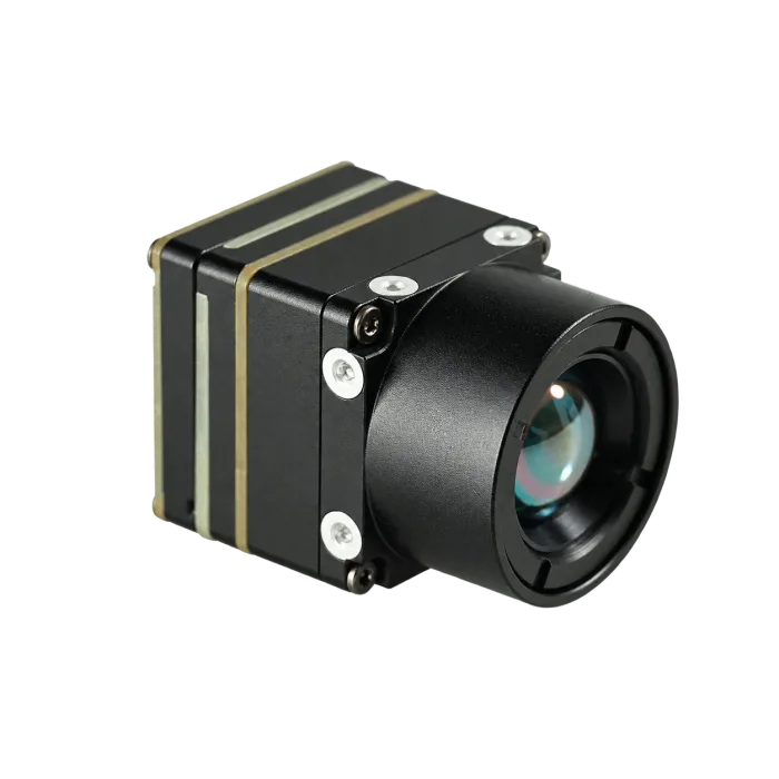
The CAMCUDA AeroMini 640 combines a 640×512, 12 μm VOx array with a choice of interface packages for OEM integration. Its non-radiometric version defaults to 60 Hz, with a 30 Hz factory option. Enquire separately about the 25 Hz radiometric version when the project needs calibrated temperature data. Keep the lens, interface board, and output requirements explicit when ordering.
| Specification Parameter | Technical Detail / Reference Value |
|---|---|
| Model Identifier | CAMCUDA AeroMini 640 60 Hz imaging |
| Detector / Array / Pitch | Uncooled VOx; 640 × 512; 12 μm |
| Spectral Response | 8–14 μm LWIR |
| Thermal Sensitivity (NETD) | ≤30 mK at 25°C, F/1.0; sensitivity is not temperature accuracy |
| Non-radiometric Frame Rate | 60 Hz default; 30 Hz factory option selected when ordering |
| Radiometric Version | 25 Hz; availability enquiry only. Documented lenses: 9 / 13 / 18 mm; confirm interface, accuracy, and data format |
| Non-radiometric Lens Options | 4 / 7 / 9 / 13 / 18 / 25 / 35 / 50 mm listed in the current selector. The pictured 9 mm version lists 48.7° H × 38.6° V FOV |
| Interface Packages | USB + CVBS + MIPI; Type-C + CVBS; or both tailboards. Match board, firmware, output format, and host; the Type-C board has different connectors |
| Power Inputs | Board-dependent. The illustrated 16-pin POWER_IN1 and 26-pin POWER_IN2 inputs are 5 V only; do not connect them to 12 V |
| Typical Module Power | <0.5 W at 25°C; complete-kit consumption may differ |
| Operating Temperature | −40°C to +80°C; evaluate the complete enclosure and selected optics separately |
| Dimensions / Weight | 21 × 21 × 28 mm / <20 g, excluding lens and flange; confirm complete assembly size and mass |
Integration & Engineering Checklist for AeroMini 640:
- ⚙️ Optics Selection: Use the current lens/FOV table, working distance, and target size to select the factory configuration. Confirm the selected lens configuration when ordering rather than assuming field interchangeability.
- ⚙️ Electrical Interface: Match the supplied board to the connector diagram and signal table. The USB + CVBS + MIPI board and Type-C + CVBS board are separate configurations.
- ⚙️ Host Software: The official AeroMini SDK FAQ points to a public technical resource folder with manuals, USB Client Software.zip, and USB-SDK.zip. The FAQ describes the SDK archive as Linux drivers, examples, and SDK resources; confirm the version and host requirements before integration.
- ⚙️ Power & Thermal Design: Follow the matched board’s supply limits, including 5 V only on the illustrated POWER_IN1 / POWER_IN2 pins. Budget complete-kit loads and validate heat transfer in the final enclosure.
Specifications: current AeroMini product table. The official PDF provides board and connector references; page 3 covers the illustrated 16-pin USB/CVBS interface. Resource links are documentation references, not a claim that the SDK has been inspected or compatibility-tested for your host.
View AeroMini 640 Configurations ➔
Product Showcase 2: CAMCUDA AI VisionCube DT Pro Dual-Visible & Thermal AI Camera Module
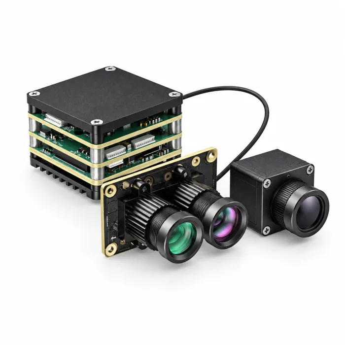
The CAMCUDA AI VisionCube DT Pro pairs wide-angle and telephoto visible cameras with a 640×512 thermal camera and 6 TOPS processing for civilian inspection and observation. Visible output is 1920×1080 at 30 Hz; thermal output is 640×512 at 50 Hz. These values describe DT Pro, not every VisionCube model: S and D have no thermal camera, and ST / DT use a different thermal resolution and rate.
| Subsystem Category | Engineering Specification Parameter | Reference Value / Capability |
|---|---|---|
| Selected Configuration | Model | CAMCUDA AI VisionCube DT Pro |
| Processing Board | AI Processing | 6 TOPS; confirm delivered AI software and integration interface |
| Processing Board | Input Voltage | 9–16 V, processing-board reference |
| Processing Board | Dimensions / Mounting | 38 × 38 × 29 mm; mounting 25.5 × 25.5 mm, board only |
| Processing Board | Weight / Display | 43.8 g board weight; picture-in-picture supported according to the brochure |
| Dual Visible Cameras | Output | 1920 × 1080 at 30 Hz |
| Dual Visible Cameras | Optics / FOV | 3.9 mm wide-angle: 72° H × 45° V; 12 mm telephoto: 26° H × 15° V |
| Dual Visible Cameras | Camera Dimensions | 40.8 × 25 × 26 mm, camera component reference |
| Thermal Camera | Resolution / Frame Rate | 640 × 512 at 50 Hz |
| Thermal Camera | Pixel Pitch / Spectral Response | 12 μm; 8–14 μm LWIR |
| Thermal Camera | Optics / FOV | 9.1 mm; 45.9° H × 36.9° V |
| Thermal Camera | Component Dimensions / Weight | 26 × 26 × 21.1 mm / ≤23 g, excluding lens and connectors |
| Thermal Camera | Interface | USB listed for the thermal camera; this does not define the complete kit’s AI, video, or control interface |
| Measurement Scope | Radiometry | The brochure does not specify calibrated temperature-measurement range or accuracy; do not assume radiometric capability |
| Complete Assembly | Integration Boundary | Board and camera figures are component references. Confirm the assembled dimensions, total mass, power, accessories, and software before ordering |
Integration Notes for System Architects: Use the current VisionCube specifications and request its own DT Pro AI-interface, video/control, and software integration documentation. Confirm the available commands and outputs, connector definitions, electrical levels, host requirements, and included accessories before freezing a carrier or wiring harness. AeroMini’s SDK, 16-pin diagram, and power definitions do not establish compatibility with VisionCube.
The product page attributes these component specifications to the supplied AI VisionCube brochure dated 2026-03-04. Supplier demonstration distances, speeds, and tracking annotations are not guaranteed specifications or an acceptance test for the selected configuration. Validate the actual hardware and software against the inspection scenes, timing, and output requirements in your project.
View AI VisionCube DT Pro Configurations ➔
6. Bill of Materials (BOM) & TCO: Hidden Engineering Costs of Consumer Conversion
In the shop, selecting a $300 consumer thermal gadget over a $1,000 OEM configuration might make your prototype BOM look attractive. Treat those figures as an illustrative comparison, not current quotations. A realistic Total Cost of Ownership (TCO) analysis should add Non-Recurring Engineering (NRE), host computing, mechanical design, qualification, maintenance, and replacement costs. A consumer camera can still be economical when its supported workflow already meets the requirement.
Look at mechanical packaging first. Removing a consumer enclosure can expose fragile connectors, alter cooling, and create a need for custom brackets and strain relief. An OEM module can provide a more useful starting point, but mounting patterns and thermal contact surfaces remain model-specific. For AeroMini, the published dimensions and mass exclude lens and flange. For VisionCube, the processing-board and camera dimensions are separate component references. Obtain the selected assembly drawing and verify vibration, clearance, and cable retention.
Then assess thermal management. Heat from the detector electronics, interface hardware, and processing board can affect image stability and component temperatures. Design the conduction path and airflow around the selected assembly, and test startup, sustained operation, and ambient changes in the intended enclosure. A low typical module-power value does not establish complete-system heat dissipation or guarantee reliable operation in a sealed housing.
Finally, review ongoing software maintenance. Ask what drivers, SDKs, command references, supported host versions, and update policies are actually supplied. AeroMini has its own SDK FAQ and resources; VisionCube requires its own AI and camera integration documentation. Do not assume shared SDKs, ROS nodes, native autopilot support, or a guaranteed production lifetime. Compare a consumer camera, a standalone OEM core, and an integrated AI module using the engineering work each leaves with your team.
AeroMini Board and Cable References for Integration Planning
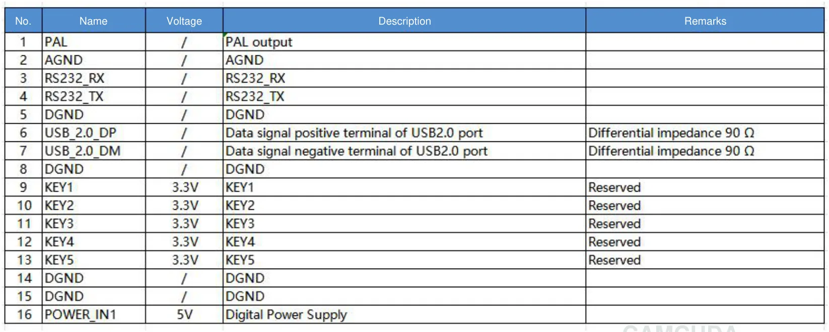
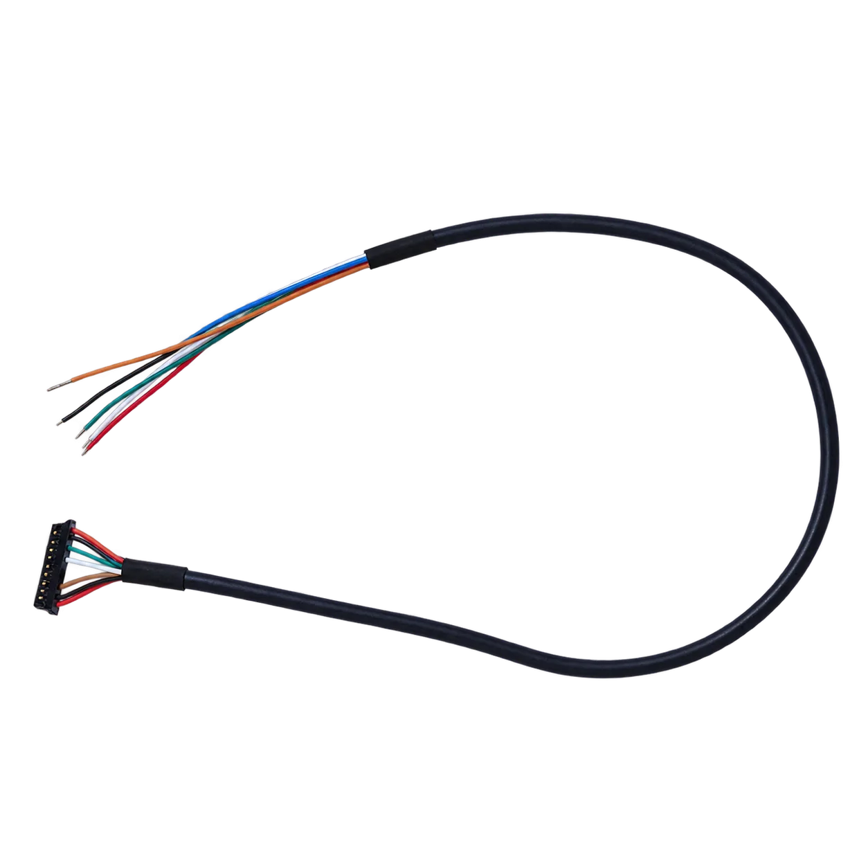
The following references apply to the illustrated AeroMini USB + CVBS + MIPI tailboard configuration. The Type-C + CVBS board is separate; do not apply these 16-pin or 26-pin definitions to its connectors or to VisionCube.
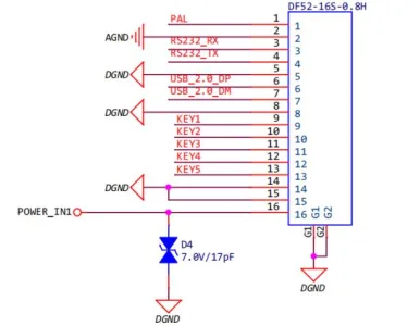
Read the schematic with the complete 16-pin signal table and official AeroMini PDF, page 3. The table identifies pin 6 as USB_2.0_DP, pin 7 as USB_2.0_DM, and pin 16 as POWER_IN1 (5 V). Match the supplied board revision, connector orientation, and cable before wiring. The separate 26-pin MIPI/DVP reference is on page 4; its POWER_IN2 inputs are also 5 V. Do not apply 12 V to POWER_IN1 or POWER_IN2.
7. Frequently Asked Questions (FAQ)
What is the practical difference between a cheap $300 thermal camera and a commercial OEM thermal core?
Can budget thermal cameras be integrated into UAV payloads or custom diagnostic devices?
Yes, if the camera’s supported interfaces, software, packaging, and performance meet the project requirements. Include any custom mounting, power conversion, host processing, driver work, and environmental testing in the cost comparison. AeroMini 640 provides a standalone thermal-core route, while AI VisionCube DT Pro combines dual visible cameras, 640×512 thermal imaging, and 6 TOPS processing. Confirm VisionCube’s own AI interface and software documentation; neither model should be assumed to have native support for a particular flight controller. Published component weights are not complete payload weights.
Why do low-cost thermal cameras fail in precise electronics inspection and distant outdoor detection?
📚 References & Further Reading
- Industry Standard: MAVLink Micro Air Vehicle Telemetry Protocol Specifications
- Industry Standard: MIPI Alliance Camera Serial Interface 2 (CSI-2) Standard
- AeroMini Documentation: Current AeroMini 640 specifications, official PDF, and SDK FAQ
- AI Module Documentation: Current AI VisionCube specifications and configuration review
- Optical Planning: Thermal imaging calculator
- Engineering Resource: CAMCUDA Industrial Vision & Thermal Engineering Blog
- Related Technical Article: Uncooled LWIR Thermal Modules for Outdoor Security and Industrial Monitoring
For configuration and quotation support, contact Vivian, Lena, or Sophie through CAMCUDA sales support. Include the selected model, imaging or temperature-data requirement, host interface, lens, and intended quantity.