Best Thermal Drone Solutions for 2025: Engineering Selection & OEM Payload Guide
Best Thermal Drone Solutions: Engineering Selection & OEM Payload Integration Guide
Selecting the best thermal drone for industrial inspection starts with the task: the size of the feature you need to see, whether you need measured temperatures, and the payload your airframe can carry. A turnkey aircraft may simplify deployment, while an OEM thermal core gives an engineering team more choices over optics, interfaces and onboard processing. Compare the complete system, including development, validation and support costs.
For solar farms, utility assets, structural surveys and other civilian inspection work, balance SWaP-C (Size, Weight, Power, and Cost) against spatial sampling and measurement requirements. This guide covers uncooled Long-Wave Infrared (LWIR) sensor selection, Ground Sample Distance (GSD), Instantaneous Field of View (IFOV), electrical and mechanical integration, and configuration questions for an engineering RFQ.
Documentation note, 6 October 2026: The original 2025 title is retained. The product examples below have been updated against current documentation for engineering evaluation and RFQ. Confirm the selected model, lens, board and firmware before design release.
Technical author: Daniel · Hardware Support
Procurement contributors: Vivian, Lena and Sophie
Table of Contents
- 👉 1. Sensor Physics & LWIR Core Selection Criteria
- 👉 2. Resolution, Optical Matching & Johnson’s Criteria for UAVs
- 👉 3. Electrical Interfaces, Video Latency & SWaP-C Optimization
- 👉 4. Mechanical Integration, Vibration Isolation & Thermal Dissipation
- 👉 5. OEM Thermal Cores: Technical Deep-Dive & Comparison
- 👉 6. OEM Payload Integration & Custom Gimbal Engineering
- 👉 7. Frequently Asked Questions (Engineering Deep-Dive)
1. Sensor Physics & LWIR Core Selection Criteria
LWIR cameras form an image from infrared radiation reaching the detector, commonly in the 8–14 µm band for the cores discussed here. An airborne installation adds changing enclosure temperatures, airflow, vibration and a moving viewpoint. Evaluate image quality and radiometric behavior under those conditions rather than relying only on a detector specification.
First decide whether the deliverable is a viewable thermal image or quantitative temperature data. An imaging-only core can support visual inspection, but a temperature report requires a radiometric configuration with documented calibration, supported data formats and appropriate operating conditions.
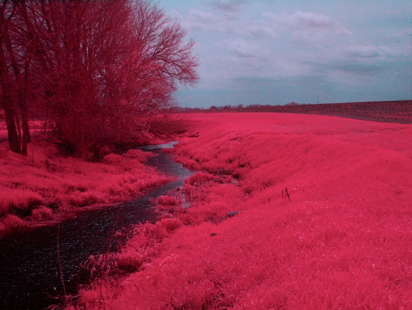
Vanadium Oxide (VOx) vs. Amorphous Silicon (a-Si)
Both VOx and a-Si are established uncooled microbolometer technologies. Compare the delivered core using matched sensitivity conditions, response time, uniformity, calibration behavior and environmental test evidence. Detector material alone does not establish which finished camera is best for a UAV or prove its resistance to vibration.
- Thermal sensitivity: Noise Equivalent Temperature Difference (NETD) describes sensitivity to small thermal contrasts under stated test conditions. Lower NETD can help distinguish subtle contrast, but NETD is not absolute temperature accuracy. AeroMini 640 publishes ≤30 mK at 25 °C and F/1.0; the SuperMini 640/640T manual publishes ≤40 mK under the same stated temperature and F-number conditions. A field measurement still depends on calibration, target sampling, emissivity and the environment.
- Pixel pitch: Compare pitch together with resolution, focal length, F-number, optical performance and field of view. A smaller pitch can change the lens design needed for a chosen field of view; it does not by itself guarantee lower lens mass or cost.
- Calibration and stability: Ask how the exact model handles warm-up, temperature drift and non-uniformity correction. Verify the radiometric configuration and its accuracy conditions separately from the imaging specification.
For background on these distinctions, see FLIR’s sensitivity guidance and infrared accuracy and uncertainty guidance. Their general explanations are useful context; use CAMCUDA’s model-specific documentation for the selected core.
Frame Rate Dynamics: Match the Inspection Task
Choose the required unique image-update rate from flight speed, target scale, scene motion and the inspection workflow. Higher update rates may help with moving scenes, but frame rate alone does not determine motion blur, capture-to-display delay or dropped frames. Validate the camera, host, encoder and downlink together.
The current configurations illustrate why one rate cannot be prescribed for every payload: AeroMini 640 non-radiometric imaging is 60 Hz by default, with a 30 Hz factory option; its radiometric version is 25 Hz and enquiry-only. SuperMini 640 imaging is 50 Hz, while SuperMini 640T thermography is 30 Hz. Check the selected stream and firmware rather than assuming an imaging rate also applies to temperature data.
2. Resolution, Optical Matching & Johnson’s Criteria for UAVs
Resolution, pixel pitch, focal length and viewing distance determine a useful first estimate of scene coverage and sampling. Flight safety, weather, terrain, optical quality and radiometric requirements must also be assessed when selecting an inspection distance.
Calculating Ground Sample Distance (GSD) and Instantaneous Field of View (IFOV)
For a small-angle approximation, near-nadir viewing and an approximately flat ground plane, GSD is the spacing between projected pixel centers. Use matching units for pixel pitch p and focal length f; GSD then has the same distance unit as height H:
GSD ≈ p × H / f
IFOV ≈ p / f radians
IFOV ≈ 1000 × p / f milliradians
Consider a generic geometry example: a 12 µm detector, a hypothetical 19 mm lens and a 60 m height above a flat inspection surface. The 19 mm lens is an example for this calculation, not an offered AeroMini or SuperMini lens configuration.
GSD ≈ (0.012 mm × 60,000 mm) / 19 mm = 37.89 mm/pixel
IFOV ≈ 0.6316 mrad
50 mm hotspot width / 37.89 mm per pixel ≈ 1.32 pixels across
A 5 cm hotspot spans only about 1.32 pixels across in this simplified example. That does not establish accurate temperature measurement, or the 3 × 3 or 4 × 4 footprint sometimes assumed in a measurement discussion. Qualitative detection and quantitative temperature measurement require different validation. Use the exact camera/lens Measurement Field of View (MFOV) or spot-size guidance, its calibration conditions and representative targets; there is no universal minimum-pixel rule for every camera.
The CAMCUDA thermal imaging calculator can support preliminary geometry comparisons. Treat its results as planning estimates, not a detection-range or temperature-accuracy guarantee. Oblique viewing, uneven terrain and lens distortion need a more complete model. FLIR’s spot-size technical note explains why single-pixel geometric sampling differs from a usable measurement area; its camera-specific guidance is not a CAMCUDA specification.
Applying Johnson’s Criteria to Airborne Thermal Payloads
Johnson-style detection, recognition and identification (DRI) criteria are approximate spatial-resolution models. Thresholds depend on the chosen model, probability level, task and scene assumptions. They help organize an evaluation, but do not guarantee aircraft altitude, field detection range or radiometric performance:
- Detection: Determine whether an object or anomaly is present against its background.
- Recognition: Distinguish its broad class, such as a vehicle, enclosure or other inspection feature.
- Identification: Resolve the particular features required by the inspection task.
At a matched field of view, a higher-resolution array provides more samples across the scene. A 1280-class core can be worth evaluating when a wide scene and small features must be covered together; a lower-resolution or 640 × 512 core may suit other tasks. Resolution alone does not provide a fixed multiplier for usable range. Both featured families below are 640 × 512, and the appropriate choice depends on optics, thermal contrast and the accepted inspection result.
3. Electrical Interfaces, Video Latency & SWaP-C Optimization
Budget the complete payload: core, lens, interface board, cables, enclosure, mounts, power conversion and companion processor. Mass and power affect the airframe and gimbal design, but the effect on endurance depends on the aircraft. Obtain assembly-level values and measure the expected operating modes.
| Interface / path | Configuration questions | Data and electrical checks | Payload validation |
|---|---|---|---|
| CVBS analog video | Does the selected board provide PAL or NTSC output? | For the SuperMini core, the CVBS pin requires an external video-buffer IC; confirm the complete output circuit. | Measure the camera-to-display chain, including any encoder and downlink. |
| USB host connection | Which board, cable, firmware and host software are supplied? | Confirm image format, unique frame rate and whether temperature data is available for that configuration. A USB connection alone does not imply radiometry. | Test enumeration, sustained capture, timestamps, buffering and recovery on the intended host. |
| MIPI / parallel digital video | Which bus and stream does the exact core support? | Match pinout, logic levels, clocks and synchronization. SuperMini 640 uses BT656; 640T provides CDS3. Its BT656 and MIPI outputs cannot operate simultaneously. | Validate the receiver and processing path with a documented sample stream. |
| Serial control | Which commands and electrical standard are available on the selected board? | AeroMini serial options are board-dependent. SuperMini core UART uses 1.8 V logic; TX/RX are defined from the core. | Verify level translation, command behavior and noise susceptibility with the payload powered. |
AeroMini Board Selection and Wiring
The AeroMini USB + CVBS + MIPI and Type-C + CVBS tailboards are distinct configurations. The illustrated 16-pin USB/CVBS and 26-pin MIPI/DVP references belong to the documented board; do not apply them to the Type-C board. In those illustrated references, POWER_IN1 and POWER_IN2 are 5 V inputs. Do not connect them to 12 V. A family-level voltage entry does not override the selected board’s pin definitions.

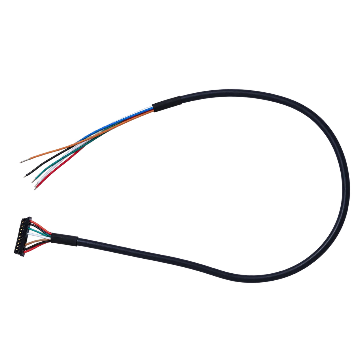
Check the AeroMini 16-pin reference and signal table and the 26-pin reference against the delivered hardware before wiring. Request the matched guide for a Type-C configuration instead of inferring its pinout from another board.
Video Processing Streams and Autopilot Telemetry
Define video, temperature data and control as separate integration requirements. A colorized image or raw sensor stream is not automatically calibrated per-pixel temperature data. For AeroMini radiometry, confirm the data format and accuracy with the quoted configuration. For SuperMini 640T, use the manual’s CDS3 and temperature-data definitions; do not apply them to the imaging-only 640.
Measure end-to-end delay between stated endpoints under representative load, including acquisition, camera processing, host buffers, encoding, downlink and display or analysis. Record dropped frames and behavior during correction events. No fixed millisecond value follows from the interface name alone.
Serial electrical standards do not guarantee command compatibility with an autopilot or MAVLink. Any bridge to aircraft telemetry needs an explicitly designed and tested software path. Differential signaling may be useful in a noisy installation, but cable routing, shielding, grounding and power integrity still need testing with motors, radios and processors active.
For the SuperMini bare-core connector, use the V1.0.0 30-pin orientation and full signal table and the power requirements. MAIN_POWER at 3.8–5.2 V is only one rail: the documented +3.3 V and +1.8 V supplies, noise limits and power-on timing also matter. Expansion-board inputs must be checked in their own documentation.
4. Mechanical Integration, Vibration Isolation & Thermal Dissipation
A successful bench image is one integration milestone. A gimbal-mounted camera also needs verified clearances, cable motion, balance, structural support and thermal behavior over the intended flight conditions.
Gimbal Center of Gravity (CoG) & Moment of Inertia
Locate the complete payload’s center of gravity relative to the gimbal axes and account for lens and cable mass. Balance, moment of inertia and motor torque should be evaluated together. AeroMini’s 21 × 21 × 28 mm and <20 g figures exclude the lens and flange. SuperMini’s 13 × 13 × 13.4 mm and <3.5 g figures describe the bare core, excluding optics and boards. Neither set of figures describes a completed flight-ready payload.
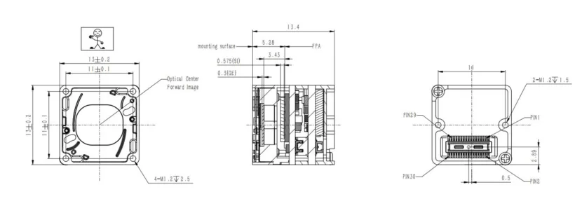
Request a dimensioned drawing for the exact AeroMini lens, flange and board assembly before releasing the enclosure. Its linked datasheet supplies interface references rather than a dimensioned assembly drawing. For SuperMini, use the bare-core drawing only for that scope and obtain the drawing for the ordered optical assembly.
Vibration Damping and Shock Tolerances
Measure the airframe and gimbal vibration environment, then agree a qualification plan for the selected camera assembly, mounting and cable support. Ask for the test profile, axes, duration and acceptance criteria rather than transferring shock or vibration figures between camera families.
SuperMini’s manual lists module environmental specifications; these do not establish completed-payload qualification. The reviewed AeroMini documentation does not establish a shock, vibration or MTBF rating. Request configuration-specific evidence and verify image stability, fastener retention and connector behavior in the intended installation.
Thermal Equilibrium & Heat Sinking
Follow the selected core’s thermal mounting guidance and evaluate heat flow from nearby processors, power electronics and the enclosure. A conductive mount or thermal pad may be appropriate, but one enclosure architecture cannot guarantee measurement stability. Test warm-up, airflow changes and enclosure-temperature transitions with the intended lens and correction settings.
Operating and storage ranges are different from the ambient conditions specified for thermography. In particular, the SuperMini manual distinguishes general operation from its −20 °C to +60 °C thermography ambient range. Confirm the full calibration and accuracy conditions for a temperature-measurement payload; non-uniformity correction does not replace that validation.
5. OEM Thermal Cores: Technical Deep-Dive & Comparison
The current featured examples serve two integration approaches: AeroMini 640 as an interface-kit route, and SuperMini 640/640T as a compact bare-core comparison. Both families are 640 × 512. Choose between them from the required data, optics, electrical architecture and assembly budget, rather than treating one as a universal winner.
CAMCUDA AeroMini 640: Interface-Kit Route for OEM UAV Payloads
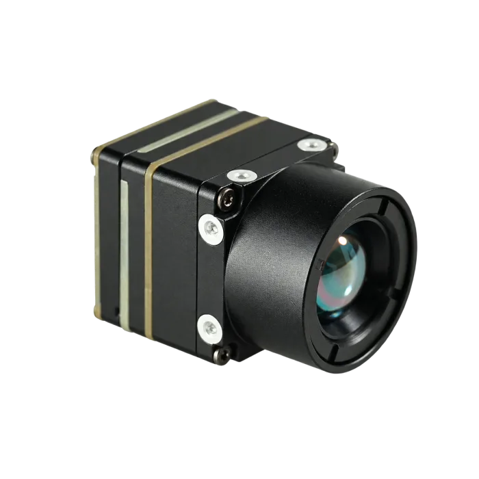
AeroMini 640 is a candidate when an OEM team wants to start with documented USB/CVBS/MIPI or Type-C/CVBS board choices. Select the imaging or radiometric version first, then match the lens and interface. An imaging kit’s rate, output format or board guide must not be assumed to apply unchanged to the radiometric configuration.
| Detector / array | Uncooled VOx; 640 × 512; 12 µm pixel pitch; 8–14 µm LWIR |
|---|---|
| Frame rate | Non-radiometric: 60 Hz default, 30 Hz factory option. Radiometric: 25 Hz, availability enquiry only. |
| NETD | ≤30 mK at 25 °C, F/1.0; a sensitivity specification, not absolute temperature accuracy. |
| Size and mass | 21 × 21 × 28 mm; <20 g. Both exclude the lens and flange; confirm complete assembly values. |
| Power | Typical module consumption <0.5 W at 25 °C. Complete-kit consumption may differ. |
| Interface package | Non-radiometric: USB + CVBS + MIPI tailboard, Type-C + CVBS tailboard, or both packages. Radiometric interface requires confirmation. |
| Supply and control | Board-dependent. Illustrated 16/26-pin POWER_IN1 / POWER_IN2 inputs are 5 V only. UART, RS232 and RS422 availability depends on the board. |
| Optics and radiometry | The product page documents multiple imaging lenses; radiometric lens options are 9 / 13 / 18 mm, by enquiry. Confirm calibration, accuracy and temperature-data format for the ordered combination. |
Use the AeroMini product page and official datasheet for configuration review. The AeroMini SDK FAQ links the product’s Linux drivers, examples and SDK resources; confirm board, firmware, host, format and rate before integration. Those resources are AeroMini-specific.
Review AeroMini 640 options and request a configuration quote
CAMCUDA SuperMini 640 / 640T: Compact Bare-Core Comparison
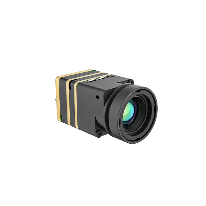
SuperMini’s small bare core is relevant when the team can design around its power rails, connector and model-specific streams. Choose 640 for imaging or 640T for thermography. Include optics, expansion circuitry, cable support and thermal mounting in the payload budget before comparing it with an assembled interface kit.
| Detector / array | Uncooled VOx; 640 × 512; 8 µm pixel pitch |
|---|---|
| Model and frame rate | SuperMini 640: imaging, 50 Hz. SuperMini 640T: thermography, 30 Hz. |
| NETD | ≤40 mK at 25 °C, F/1.0, as specified in Product Manual V1.0.0. |
| Bare-core size and mass | 13 × 13 × 13.4 mm; <3.5 g. Excludes optics and interface/expansion boards. |
| Core connector / supply | 30-pin interface. MAIN_POWER 3.8–5.2 V, plus +3.3 V and +1.8 V rails. Follow the manual’s tolerances, noise limits and power-on timing. |
| Video paths | 8-bit LVCMOS and 2-lane MIPI; model-specific BT656 for 640 and CDS3 image-plus-temperature data for 640T. BT656 and MIPI cannot operate simultaneously. |
| Control and analog output | 1.8 V UART logic; TX/RX are core-referenced. CVBS requires an external video-buffer IC. USB pins do not alone establish a ready-to-use USB kit. |
| Thermography scope | 640T only. Use the manual’s measurement and accuracy conditions, including the −20 °C to +60 °C thermography ambient range. Confirm the chosen lens, board and data path. |
Start with the SuperMini product page and English Product Manual V1.0.0. Request software and integration support for the exact SuperMini configuration; AeroMini SDK resources are not SuperMini compatibility evidence.
Review SuperMini 640 / 640T and request a configuration quote
Direct Engineering Comparison Matrix
The central tradeoff is the delivered integration package and assembly design, not a 1280-versus-640 resolution comparison. A smaller bare core can still require substantial optical, electrical and mechanical development.
| Engineering decision | AeroMini 640 | SuperMini 640 / 640T |
|---|---|---|
| Integration starting point | Evaluate documented interface-kit options for the selected board. | Evaluate a compact bare core and the additional power, board and host integration it requires. |
| Array / pixel pitch | 640 × 512 / 12 µm | 640 × 512 / 8 µm |
| Imaging / thermography rate | 60 Hz imaging default; 30 Hz factory option. 25 Hz radiometric enquiry. | 640: 50 Hz imaging. 640T: 30 Hz thermography. |
| Mechanical budget | 21 × 21 × 28 mm; <20 g, excluding lens and flange. | 13 × 13 × 13.4 mm; <3.5 g bare, excluding optics and boards. |
| Electrical review | Select USB + CVBS + MIPI or Type-C + CVBS documentation; verify the board’s supply and serial options. | Review the 30-pin core, all three rails, 1.8 V UART and any required expansion circuitry. |
| Radiometric decision | Confirm 25 Hz version, lens, interface, data format and accuracy by RFQ. | Select 640T and validate its documented temperature stream and measurement conditions. |
| Before enclosure release | Request the exact lens/flange/board assembly drawing. | Match the bare-core or assembly drawing to the hardware actually ordered. |
6. OEM Payload Integration & Custom Gimbal Engineering
Selecting the best thermal drone configuration takes a structured evaluation of the complete civilian inspection payload. Define acceptance criteria before committing to enclosure tooling or a production purchase.
Stage 1: Optical Matching and Field of View Selection
Record the smallest relevant feature, working distance, scene coverage and whether the result is visual detection or temperature measurement. Use preliminary GSD and IFOV calculations, then review lens performance and model-specific MFOV or spot-size guidance. Validate representative targets at the intended viewpoints. No focal length or altitude is universally sufficient for solar, structural or utility inspection.
For AeroMini radiometry, work within the documented 9 / 13 / 18 mm enquiry options unless a different calibrated configuration is explicitly confirmed. For either family, request the drawing and calibration scope for the selected lens. Aircraft clearance and site-safety decisions require a separate operational assessment.
Stage 2: Electrical & Companion Computer Architecture
- AeroMini interface-kit evaluation: Specify the required tailboard and cable, supply, host operating system, video format and unique update rate. Test the matched software path before assuming compatibility with an embedded computer. Confirm temperature-data support separately for a radiometric quote.
- SuperMini core integration: Review the 30-pin connector, rail tolerances and sequencing, UART levels, video mode and receiver timing. Include required buffering or expansion boards, and verify the exact 640 or 640T stream on the chosen host.
- System timing and power: Measure complete-payload power and capture-to-analysis latency under representative processing and radio loads. Document recovery after power interruption, connection loss and any correction event.
Stage 3: Image Processing Pipeline & Radiometric Calibration
- Non-uniformity correction: Follow the selected model’s documented correction method and account for any temporary interruption of image delivery. NUC or shutter correction addresses non-uniformity and drift; it does not establish traceable absolute calibration by itself.
- Detail enhancement and palettes: Confirm which controls the selected firmware supports. Contrast enhancement and a color palette change image presentation; they do not create temperature accuracy or restore spatial detail that was not captured.
- Radiometric validation: Confirm lens calibration, emissivity and reflected-temperature settings, ambient limits and temperature-data interpretation. Check representative targets using a suitable reference method and document uncertainty for the inspection task.
For general background on the distinction between calibration and correction, see FLIR’s calibration documentation. The selected CAMCUDA model’s documentation and acceptance tests govern its use.
RFQ checklist: Include the civilian application, smallest feature and working distance, required field of view, imaging or radiometric output, lens preference, host and interface, complete-assembly size/mass/power limits, environmental conditions, sample quantity and acceptance tests. Ask for the matched drawing, pinout, manual, software resources, calibration evidence and procurement documents. Confirm price, availability and lead time in the quotation.
7. Frequently Asked Questions (Engineering Deep-Dive)
How should I compare the cost of turnkey thermal drones and modular OEM payloads?
Compare total project cost rather than assuming a fixed percentage saving. A turnkey system may include an aircraft, gimbal, software, support and established workflows. An OEM design adds engineering, optics, boards, enclosure work, qualification and ongoing maintenance. Ask for itemized quotations and check data access, software licensing and support terms for each option. AeroMini and SuperMini configurations do not establish a universal cost advantage or a direct connection to an autopilot.
What is the minimum thermal sensor resolution required for actionable UAV inspections?
There is no single minimum resolution for every inspection. Start with feature size, field of view, working distance, contrast and the required output. Lower-resolution cores may suit some tasks; 640 × 512 or a generic 1280-class option can provide more scene samples when needed. For temperature measurement, verify the exact lens/core MFOV, calibration and representative-target results. Neither a pixel count nor a NETD value alone certifies an inspection.
What documentation is needed to assess NDAA and government procurement requirements?
Request model-specific origin and supply-chain information, component documentation, any applicable declarations and the exact configuration being quoted. Have the purchasing organization assess those materials against its contract and current requirements. An OEM architecture or product-page claim alone does not establish certification, legal eligibility or an audit outcome. Include the requested evidence in the RFQ without assuming that a declaration is available or sufficient.
How do ambient air temperatures and wind speeds affect aerial thermal measurements?
Wind and rotor airflow can change a target’s surface temperature, while enclosure-temperature changes can affect camera behavior. Record the conditions, consider the viewpoint and airflow around the inspected surface, and follow the selected radiometric model’s warm-up, correction and calibration guidance. Validate within its stated thermography ambient range. General operating or storage limits do not extend a temperature-accuracy specification.
How should I choose the frame rate for a drone-mounted thermal camera?
Choose the unique image-update rate from scene motion, flight speed, sampling needs and the inspection workflow, then test the complete capture-to-analysis path. A 50 or 60 Hz imaging stream is not essential for every task: current AeroMini radiometry is 25 Hz by enquiry, and SuperMini 640T thermography is 30 Hz. A 9 Hz rate alone does not determine blur or usability, and no rate by itself guarantees gimbal stability, low latency or zero dropped frames.
References & Further Reading
- AeroMini 640 current product specifications, datasheet and interface references, and model-specific SDK FAQ
- SuperMini 640 / 640T current product information and Product Manual V1.0.0, including core interfaces, electrical requirements and mechanical scope
- LYNRED detector-material research context: material-level findings require finished-camera validation
- EMVA 1288 standard-owner page: general camera-characterization context, not evidence of CAMCUDA radiometric certification or payload qualification
- CAMCUDA thermal imaging calculator for preliminary geometry; thermal imaging applications and engineering blog resources