UAV thermal imaging camera: 2026 Practical Field Note for Reliable Utility Payload Handoffs
A uav thermal imaging camera project usually looks easy after the first successful demo flight. The hard part starts later, when the payload has to move from a borrowed gimbal or bench setup into a repeatable OEM airframe with the right video path, weight budget, control interface, and procurement paperwork. That is where utility and industrial drone teams often lose time.
Quick answer
If your team is evaluating a uav thermal imaging camera for utility or industrial inspection, lock the mission, live-view path, recorder path, and host interface before you freeze the payload stack. The featured CAMCUDA AeroMini 640 non-radiometric 9 mm configuration offers 640 × 512 imaging with the USB + CVBS + MIPI package, 60 Hz default or a 30 Hz factory option. It does not measure temperature. Confirm the supplied board, actual output rates, control pins and documentation package during RFQ.
UAV thermal imaging camera selection map for repeatable missions
The fastest way to waste a month on a uav thermal imaging camera program is to treat the thermal module as a simple line item. Utility and industrial teams usually need four things to line up at once: mission visibility, pilot viewing, host integration, and procurement timing. Once one of those is left vague, the field demo and the final payload start to drift apart.
| Decision area | What to confirm early | Why it matters to the final payload |
|---|---|---|
| Mission scene | Substation scan, line inspection, rooftop heat-contrast review, or perimeter sweep; state whether temperature values are required | Sets lens/FOV, working distance, and whether the payload is optimized for detection or operator interpretation |
| Live-view path | Pilot monitor, ground recorder, onboard computer, or a mix of all three | Drives whether bench-friendly USB is enough or whether low-latency analog viewing still needs to stay in the conversation |
| Control path | Selected board, serial-control pins and electrical levels, required commands and host architecture | Affects host-board planning, wiring, debugging method, and test repeatability |
| SWaP budget | Weight, power draw, connector route, and mechanical envelope | Determines if the module still fits after gimbal, downlink, compute board, and enclosure choices are finalized |
| Procurement packet | Datasheet, matched interface reference, ordered-assembly drawing and contract-specific procurement evidence | Keeps sampling and North America review from stalling after engineering has already chosen the video path |
This is a systems-level handoff: the module, host, recorder and field display must support the same mission requirements. For a CAMCUDA buyer, that translates into a simple rule: pick the thermal module as part of the payload workflow, not as an isolated spec block. Record the data path, power budget and deployment constraints before comparing samples.
Featured product parameters for this UAV thermal imaging camera workflow
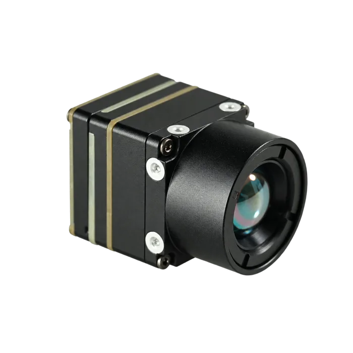
CAMCUDA’s featured starting point here is the CAMCUDA AeroMini 640 non-radiometric 9 mm configuration. Its F1.0 lens has a listed 48.7° horizontal × 38.6° vertical field of view. The USB + CVBS + MIPI kit includes the module and 9 mm lens, tailboard and USB cable; customer soldering is required. It is a module-level option for teams building a uav thermal imaging camera payload. Engineering still defines the host stack, enclosure and viewing path; the module references below do not establish complete-kit dimensions or power.
| Product | CAMCUDA AeroMini 640 — non-radiometric 9 mm, USB + CVBS + MIPI |
|---|---|
| Configuration pricing | Request a current quote for the non-radiometric 9 mm kit, selected tailboard and 60 Hz default or 30 Hz factory option; confirm supplied items and delivery terms |
| Detector type | Vanadium oxide uncooled infrared focal plane detector |
| Resolution | 640 × 512 |
| Pixel pitch | 12 μm |
| Spectral range | 8-14 μm |
| NETD | ≤30 mK at 25 °C, F/1.0 |
| Imaging frame rate | 60 Hz default / 30 Hz factory option; confirm the actual rate of each required output |
| Power | Illustrated POWER_IN1 / POWER_IN2 inputs: 5 V only, not 12 V. <0.5 W typical module consumption at 25 °C; complete-kit power may differ |
| Selected video and control paths | USB + CVBS + MIPI package; confirm the output combination. Illustrated 16-pin: RS232_RX/TX on pins 3/4; separate 26-pin: 3.3 V UART. Match the supplied board guide |
| Analog note | CVBS on the selected board; confirm PAL/NTSC, receiver compatibility and concurrent output requirements |
| Weight and size | <20 g; 21 × 21 × 28 mm, excluding lens and flange. Request the complete ordered 9 mm assembly dimensions and mass |
| Environment | −40 °C to +80 °C operating; −50 °C to +85 °C storage. Validate the complete payload against its requirements |
For teams comparing modules in the thermal imaging cores category, the point is not only that these numbers look suitable on paper. The point is that they can be turned into a practical payload plan with enough clarity to support sampling, host-board validation, and RFQ preparation.
Field handoff: when a good demo flight is not yet a deployable payload
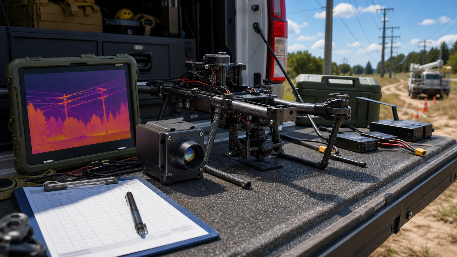
In this illustrative scenario, a utility contractor runs one promising evening inspection flight over a compact substation. The pilot can see thermal contrast, and the customer wants to explore the concept. The OEM team then has to rebuild that viewing workflow on its own airframe, with its own monitor, recorder, compute board, cable routing, and documentation requirements. A uav thermal imaging camera demo provides observations for acceptance planning; it does not prove final mission fit or temperature-measurement capability.
The first trap is assuming the demo setup already answered the integration questions. It usually did not. A borrowed payload may hide the live-view latency, the host-side control path, the power overhead, or the recorder limitations. A practical module-level path lets the team separate those decisions and verify them one by one.
AeroMini 640 gives the team a configuration to evaluate in this handoff. Start bench validation over USB, identify the required control commands, and confirm whether the final aircraft needs CVBS for an existing monitor, recorder or downlink. Check the selected board, PAL/NTSC format, output combination and measured end-to-end latency. The pilot’s display path and the final recorder path each need their own acceptance test.
The practical lesson is to define the payload workflow as well as the sensor resolution. State what the operator must see, what the recorder must capture, and what the host must control. Carry those requirements into the RFQ so a successful demonstration can become a testable production handoff.
The interface plan usually decides whether a UAV thermal imaging camera program moves fast
When buyers ask whether a uav thermal imaging camera supports “the same view the pilot saw in the demo,” they are often asking three different questions at once:
- Can engineering validate the payload quickly on a bench or embedded host?
- Can the pilot or operator still get a clean live view during flight?
- Can the control path and recorder path survive the final aircraft architecture?

For this featured AeroMini configuration, evaluate USB capture and any required CVBS or MIPI path against the selected board and host. On the illustrated 16-pin USB/CVBS board, control pins 3/4 are labelled RS232_RX/TX; the separate 26-pin MIPI/DVP guide specifies 3.3 V UART. USB video alone does not establish USB serial control. Confirm the board revision, connector orientation, electrical levels, firmware, video formats and actual output rates before wiring or software integration.
Analog should not be treated as an outdated afterthought. For some payloads, older field monitors, existing recorders or analog downlinks keep CVBS relevant. For the selected AeroMini board, confirm PAL/NTSC format, receiver compatibility, required output combinations and measured end-to-end latency. Record the exact model, board, firmware and host in the RFQ; do not assume every listed interface operates simultaneously at the factory frame rate.
If your team is still deciding whether the final payload will use only digital paths, review the host-side expectations against the broader interface stack before the airframe and gimbal are locked. That is less expensive than discovering late that the demo workflow depended on a monitor or transmitter path no one documented clearly.
For reference on USB video class expectations in host-side development, the USB-IF video class documentation can help frame validation questions. It is standards background, not evidence that this AeroMini configuration implements a particular UVC profile or has been tested with your host. Confirm those details in the matched product documentation and bench tests.
Common deployment risks after the thermal image already looked good once
1. Freezing the lens or enclosure before the live-view path
Teams often optimize the mechanical package first, then discover the chosen display or recorder path needs a different connector route or board arrangement.
2. Treating the demo payload as proof of host compatibility
A working demo does not automatically validate the final onboard computer, firmware behavior, power distribution, or recording workflow.
3. Ignoring SWaP creep after adding the rest of the payload stack
The module may be light, but the final UAV thermal imaging camera payload also includes the mount, downlink, storage, compute board, and cabling. The full stack matters.
4. Waiting too long to request documentation
Request drawings, matched interface references and document revisions early. If the buyer’s applicable contract calls for NDAA-related evidence or CE/RoHS materials, identify the exact model and configuration, confirm which documents are available, and have the purchaser review their scope before the procurement deadline.
Data path and deployment conditions matter just as much as the component headline. That is a useful way to think about a uav thermal imaging camera payload too. The thermal image only becomes commercially useful when the whole system behaves predictably in the field, so define repeatable tests for capture, live viewing, control, power and recording.
RFQ packet for a utility or industrial UAV thermal imaging camera buy
A clean RFQ is usually the difference between a fast sample cycle and a week of clarification emails. If your team is moving from a proof flight to an OEM payload program, include the practical details below:
| RFQ item | Why CAMCUDA needs it |
|---|---|
| Mission type and working distance | Helps align the module, lens/FOV, and operator expectations |
| Preferred live-view path | Names the USB capture host and any CVBS receiver or MIPI path, required formats, measured latency and recording tests |
| Host board and control path | Matches the supplied AeroMini board, control pins, electrical levels and commands to the host |
| Weight, power, and enclosure limits | Prevents late-stage payload-stack conflicts |
| Documentation needs | Identifies datasheets, matched interface references, ordered-assembly drawings and model-specific review materials to request |
| North America procurement review | If the buyer’s applicable contract requires NDAA-related evidence, identify the exact model and configuration, confirm which documents are available, and have the purchaser review their scope |
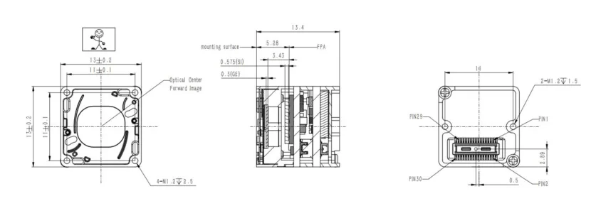
For a separate bare-core comparison, CAMCUDA SuperMini 640, CC-SM640-I50, provides 640 × 512 non-radiometric imaging at 50 Hz. Its 13 × 13 × 13.4 mm dimensions and under-3.5 g mass exclude the lens and expansion board. This is a distinct core with its own 30-pin connector, power rails and 1.8 V UART; review its Product Manual V1.0.0, PDF pages 6–8 before host design. The drawing below belongs to this SuperMini bare core, not the AeroMini 9 mm assembly. Request the complete ordered AeroMini 9 mm drawing for the payload bracket; the published AeroMini STEP resource represents the 7 mm model.
North America buyers should raise procurement requirements with the first RFQ. Identify the exact model, configuration, destination and intended use, and ask which NDAA-related statements, CE/RoHS materials and other model-specific documents are available for the buyer’s applicable contract. The purchaser must review the documents’ scope against that contract; a product page or statement alone does not establish eligibility. Keep interface references and ordered-assembly drawings in the same review packet. The FAR 52.204-25 reference provides clause context only, not a CAMCUDA compliance determination.
Next step if your demo flight needs to become a repeatable payload
If your team is narrowing a uav thermal imaging camera path for utility, industrial, or outdoor drone work, start with the featured AeroMini 640 non-radiometric 9 mm configuration and send the interface assumptions with the RFQ. Name the USB host, any CVBS receiver or MIPI path, the selected factory frame rate, board-matched control pins and levels, and the live-view and recording tests needed before payload release.
Review the AeroMini 640 product page or compare more options in thermal imaging cores. For application context, see drone thermal camera applications and outdoor field thermal imaging. Start technical review with the AeroMini datasheet, model-specific SDK FAQ and public technical documentation folder. Match the manual, serial commands and software package to the supplied board, firmware and host; these entry points do not establish tested SDK compatibility. Use support downloads and contact / RFQ to confirm the package.
Technical author: Daniel · Hardware Support
Sales contributors: Vivian, Lena and Sophie
FAQ
Is AeroMini 640 a complete UAV thermal imaging camera or a module?
It is a module-level product for OEM integration. The selected AeroMini 640 non-radiometric 9 mm configuration provides imaging without temperature measurement. Teams still need to define the aircraft, mount, host board, monitor and recorder paths, lens/FOV, acceptance tests and documentation package around it.
Why can a UAV thermal imaging camera demo succeed but the OEM payload still fail later?
The demo may not validate the final host interface, power route, live-view latency, recorder path, enclosure, or procurement requirements. Those gaps usually appear after the first successful field flight.
Can one module support both bench testing and pilot-side viewing?
That depends on the final system design. Evaluate USB capture and any required CVBS or MIPI path on the selected AeroMini USB + CVBS + MIPI board package. Confirm PAL/NTSC where needed, receiver compatibility, which outputs can run together, their actual rates and measured latency. Match the separate control path to the supplied board and host; a successful bench image alone does not validate pilot-side viewing.
When does analog still matter in a UAV thermal imaging camera project?
Analog still comes up when teams use legacy field monitors, existing recorders, older transmitters, or a low-latency viewing chain that has not been replaced yet. That does not mean every configuration includes it by default, so the requirement should be stated clearly in the RFQ.
What should a buyer send before requesting samples?
Send the mission type, working distance, lens/FOV target, host board, preferred control path, live-view path, power budget, enclosure limits, and any documentation needs such as drawings or compliance review.
Is this module suitable only for drones?
No. The same module-level product can also fit embedded vision, outdoor monitoring, and other OEM thermal projects. The final fit depends on the host system, environment, and interface plan.
When should a North America buyer ask for NDAA paperwork?
Ask early, ideally with the first RFQ or sample discussion. If the buyer’s applicable contract requires NDAA-related evidence, identify the exact model and configuration, ask which documents are available, and have the purchaser review their scope against that contract. Do not treat a product listing or requested statement as proof of eligibility.
What is the practical reason to confirm a board-matched serial control path?
Some teams need a separate control path that matches the rest of the aircraft and ground-system architecture. On the illustrated AeroMini 16-pin USB/CVBS board, pins 3/4 are labelled RS232_RX/TX; the separate 26-pin MIPI/DVP guide specifies 3.3 V UART. Confirm the supplied board, levels, commands and host wiring. Do not infer USB serial control from USB video or apply these guides to a Type-C or SuperMini board.
What pages should a buyer review next on CAMCUDA?
Start with the featured AeroMini 640 non-radiometric 9 mm configuration, then review the broader thermal imaging cores category, drone applications, and RFQ contact page. Use the model-matched technical resource links above to prepare the host and documentation questions.