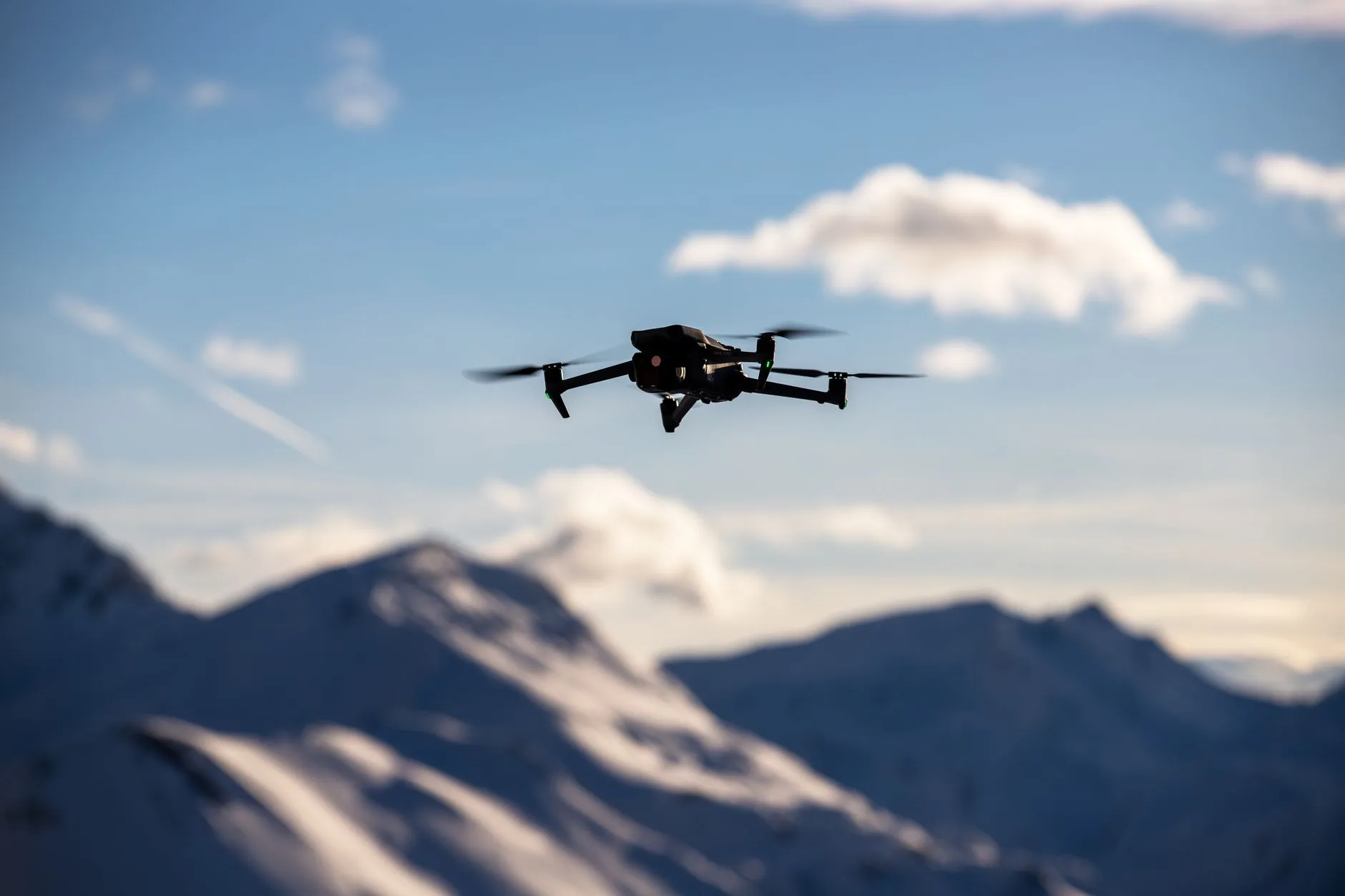
Drone with Heat Camera: OEM Selection Guide for Dual-Spectrum & AI Thermal Payloads
Drone with Heat Camera: OEM Selection Guide for Dual-Spectrum & AI Thermal Payloads
Integrating an uncooled thermal payload into an unmanned aerial vehicle (UAV) isn’t just about hooking up an analog video transmitter and sending a signal down to a monitor anymore. We have moved entirely into embedded edge-computing architectures capable of real-time multi-sensor fusion. If you are an unmanned systems engineer, OEM platform designer, or autonomous robotics integrator, choosing a drone with heat camera capabilities comes down to making hard, calculated engineering trade-offs across Size, Weight, Power, and Cost (SWaP-C). The actual bottleneck is rarely just finding a microbolometer; it is getting neural network tracking algorithms to run smoothly directly on the aircraft, managing dense thermal dissipation in tight carbon-fiber fuselages, and bypassing closed, proprietary communication protocols that lock your autopilot out of low-level video pipelines.
Here’s the deal: traditional turnkey thermal drones lock down their hardware. They restrict low-level access to video streams, force your field operators onto proprietary ground control stations (GCS), and limit flexibility with crippled software development kits (SDKs). Next-generation OEM payloads take a completely different architectural path. By combining long-wave infrared (LWIR) vanadium oxide (VOx) cores with high-frame-rate electro-optical (EO) CMOS sensors and onboard neural processing units (NPUs) pushing 4 to 6 TOPS of INT8 compute, modern dual-spectrum modules do the heavy lifting onboard. They talk directly to open-source flight controllers running ArduPilot or BetaFlight over high-speed Crossfire (CRSF) and UART, executing low-latency edge AI tracking without loading down your primary flight avionics or depending on fragile ground-station radio links.
Table of Contents
- 👉 1. Thermal Core Fundamentals: LWIR Physics, Sensor Design & UAV Integration
- 👉 2. Dual-Spectrum Sensor Fusion & Edge AI Vision Architectures
- 👉 3. Edge AI Compute Engines: Onboard Inference & Tracking Pipelines
- 👉 4. OEM Hardware Comparison: TM02-SOLO T vs. TC01-DUAL Specifications
- 👉 5. Electrical, Mechanical & Thermal SWaP-C Engineering
- 👉 6. DRI Modeling, Johnson’s Criteria & Operational Deployment
- 👉 7. Deep-Dive OEM & Integrator Technical FAQ
1. Thermal Core Fundamentals: LWIR Physics, Sensor Design & UAV Integration
When you are specking out a drone with heat camera payload, everything starts at the physical detector layer. Aerial thermal imaging operates almost exclusively in the Long-Wave Infrared (LWIR) waveband, spanning 8 µm to 14 µm. At these wavelengths, your sensor is measuring passive blackbody radiation emitted by objects in the scene rather than reflected ambient light, governed directly by Planck’s radiation law and the Stefan-Boltzmann law ($E = \sigma T^4$). Because biological targets, vehicle exhaust systems, and terrain elements emit peak radiant exitance in this band at typical atmospheric ambient temperatures (around 300 Kelvin), an LWIR detector cuts straight through total zero-lux darkness, light foliage, heavy smoke, and atmospheric haze where short-wave infrared (SWIR) or visible cameras fail completely.
The radiant flux coming off the scene has to be focused through custom optical assemblies onto an array of microbolometers. You cannot use standard crown or flint optical glass here—standard optical glass is completely opaque to LWIR wavelengths. Instead, thermal lenses must be precision-machined from chalcogenide glass or monocrystalline optical-grade Germanium. Germanium has a very high refractive index (roughly 4.0 at 10 µm) alongside exceptionally low optical dispersion across the 8–14 µm spectral band. That allows optical engineers to design compact, fast-aperture lenses with low f-numbers (typically f/1.0 to f/1.2), maximizing the raw photon flux hitting the focal plane array (FPA) in size-constrained drone gimbals.
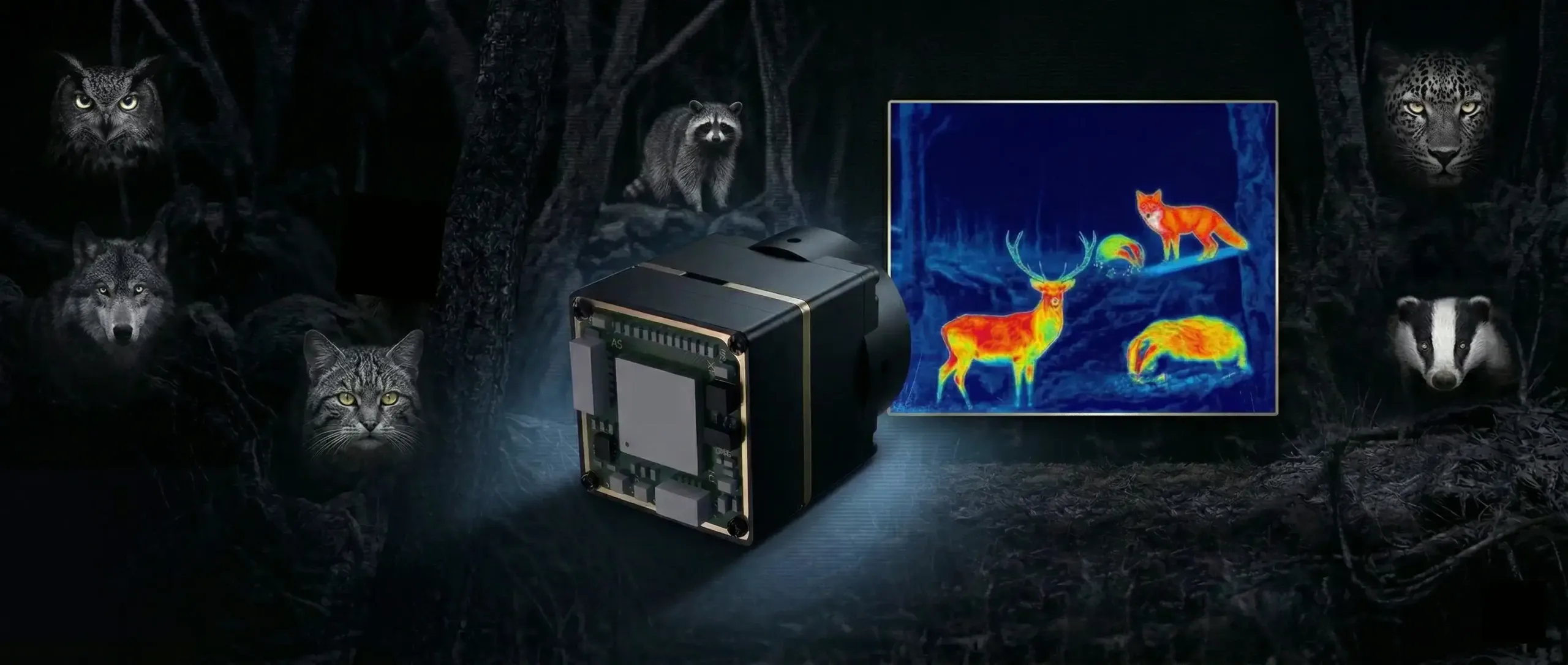
Vanadium Oxide (VOx) vs. Amorphous Silicon (a-Si) Detector Materials
Look at the microbolometer market today, and you will see two primary competing thin-film material architectures: Vanadium Oxide (VOx) and Amorphous Silicon (a-Si). In the shop, when we evaluate aerial performance, VOx is the clear winner for airborne edge tracking:
- ✅ Temperature Coefficient of Resistance (TCR): VOx delivers a significantly higher TCR (roughly 2% to 3% per Kelvin) compared to a-Si. This delivers a much stronger signal-to-noise ratio (SNR), which is critical when you are flying high-altitude search patterns where the thermal delta between ambient ground clutter and a target signature is only a fraction of a degree.
- ✅ Noise Equivalent Temperature Difference (NETD): Modern uncooled VOx microbolometers hit sensitivity ratings below 40 mK to 50 mK. Lower NETD values mean your edge detection algorithm can cleanly distinguish subtle temperature gradients—like faint residual tire tracks on asphalt or a partially obscured human heat signature under dense tree canopy.
- ✅ 12 µm Pixel Pitch Scaling: Moving from legacy 17 µm pixel architectures down to modern 12 µm pixel pitch shrinks the physical footprint of the FPA die. This shrinkage lets you use smaller, lighter Germanium optical elements to hit the exact same optical magnification and spatial resolution, slashing front-end payload weight by up to 35% without degrading your spatial sampling.
Understanding optical physics and photonics optimization is foundational when matching detector pitch to lens aperture; technical resources from Optica detail how waveband transmission efficiencies directly influence sensor modulation transfer functions (MTF).
Imaging vs. Calibrated Radiometric Payloads
Before ordering hardware, you must clearly identify whether your airframe mission requires qualitative imaging and tracking or quantitative calibrated radiometry:
- ⚙️ Radiometric Payloads: These sensors are built to measure the exact absolute surface temperature of every individual pixel in the frame. Radiometric cores rely on complex factory calibration lookup tables (LUTs), real-time ambient housing thermistors, and continuous shuttered Non-Uniformity Corrections (NUC) to zero out sensor drift. This hardware is mandatory for industrial solar farm PV degradation audits, electrical utility corona inspection, and pipeline insulation compliance.
- ⚙️ Imaging and AI Tracking Payloads: These modules prioritize thermal contrast, dynamic edge sharpness, and high dynamic range (HDR) visual tracking over calibrated temperature readings. Instead of burning compute cycles and memory bandwidth calculating absolute temperature matrices, these engines apply aggressive dynamic detail enhancement (DDE), adaptive histogram equalization, and spatial temporal filtering. This delivers maximum feature contrast into onboard neural networks, allowing continuous real-time tracking of moving vehicles and personnel in low-visibility environments.
Explore deeper design tradeoffs in our technical thermal imaging guides.
2. Dual-Spectrum Sensor Fusion & Edge AI Vision Architectures
A standalone thermal camera gives you unmatched target detection in pitch blackness, but it completely lacks surface texture, chromatic detail, and high-frequency edge definition. You cannot read a vehicle license plate, identify warning placards, or spot painted runway lines with an LWIR sensor alone. Visible electro-optical (EO) cameras provide high spatial resolution and color, but they go completely blind the moment the sun goes down or fog rolls in. Dual-spectrum systems solve this by co-locating both sensors on a single synchronized compute board.
Multi-Spectral Fusion Methodologies
Modern dual-spectrum UAV payloads implement several digital video fusion techniques directly within the onboard processing engine:
- 📌 Picture-in-Picture (PIP) Display: The primary display channel feeds wide-angle visible context while embedding a scalable, repositionable thermal window (or vice-versa). This allows an aerial pilot to maintain situational awareness of surrounding airspace and structures while tracking a localized thermal target.
- 📌 Dynamic Dual-Light Fusion (Edge Extraction): High-frequency structural outlines and textural details are extracted from the EO visible channel using Sobel or Laplacian spatial filters. These edges are dynamically blended and overlaid onto the 640×512 thermal radiance map. The resulting synthetic stream preserves the thermal heat contrast while restoring fine structural borders, wire fences, and road signage.
- 📌 Hardware-Level Parallax Correction: Because the EO visible sensor and the LWIR thermal microbolometer sit along separate physical optical axes, physical parallax occurs when focusing on close-range targets. Advanced edge processing boards run continuous real-time homography transformations and dynamic affine warping to mathematically align the visible and infrared pixels across varying target distances.
Principles of automated feature extraction and alignment in aerial sensor payloads build directly upon established machine vision concepts.
3. Edge AI Compute Engines: Onboard Inference & Tracking Pipelines
Streaming dual uncompressed video feeds down to a ground station for AI processing is an architectural dead end for autonomous operations. RF downlinks introduce noticeable latency (often 150–300 ms), eat up radio bandwidth, and collapse the moment the drone flies behind a ridge or encounters RF jamming. Edge AI architecture moves the neural network directly onto the aircraft’s payload compute engine, executing target inference in single-digit milliseconds right at the sensor level.
Neural Processing Units (NPUs): 4 TOPS vs. 6 TOPS
Modern embedded tracking boards integrate dedicated, low-power Neural Processing Units (NPUs) rated between 4 TOPS and 6 TOPS at INT8 precision:
- ⚙️ 4 TOPS Architecture (e.g., TC01-DUAL): Tuned for lightweight micro-airframes and small gimbal assemblies where power consumption must stay under tight limits. This compute block runs quantized convolutional neural networks (like YOLOv8n or MobileNet-SSD) tracking up to 60 simultaneous targets at a steady 30 ms inference cycle. It is an ideal fit for tactical reconnaissance drones, perimeter inspection multicopters, and mobile robotic scouts.
- ⚙️ 6 TOPS Architecture (e.g., TM02-SOLO T): Powered by an advanced multi-core CPU architecture (Arm Cortex-A76 at 2.4 GHz paired with Cortex-A55 at 1.8 GHz). This higher compute density enables ultra-low latency processing (~8 ms supplier reference) and scales to 120 concurrent tracks. It executes complex multi-modal tracking modes such as reticle locking, close-to-lock, route pre-mapping, lost-target re-acquisition, and dynamic tracking for interceptors moving at speeds up to 450 km/h.
Flight Controller Autopilot Integration via CRSF and UART
Rather than locking operators into closed, proprietary mission suites, embedded edge AI tracking modules interface directly with open-source flight stacks including BetaFlight and ArduPilot. When the onboard neural network identifies a target bounding box within the video frame, the AI tracking engine calculates the angular pixel error relative to the optical center. The board translates these spatial offsets into standardized Crossfire (CRSF) or MAVLink telemetry packets, streaming correction vectors directly into the flight controller over a high-speed serial UART bus. The autopilot’s onboard PID navigation loops automatically yaw the aircraft or articulate a 2-axis/3-axis brushless gimbal to track the target continuously.
For custom payload integrations and flight stack setup, review our specialized drone thermal camera application blueprints.
4. OEM Hardware Comparison: TM02-SOLO T vs. TC01-DUAL Specifications
Selecting the optimal dual-spectrum tracking engine requires matching processing throughput, optical field of view, sensor frame rates, and mechanical dimensions to the host airframe. Below is an exhaustive technical review of two industry-leading OEM tracking platforms.
6 TOPS Dual-Spectrum UAV AI Tracking Module with 640×512 Thermal Camera (TM02-SOLO T)
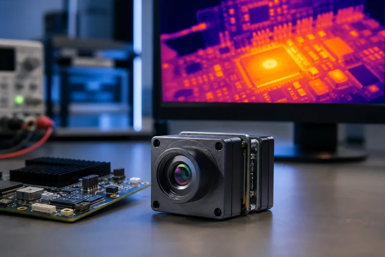
The TM02-SOLO T is an advanced dual-spectrum UAV AI tracking module engineered for system integrators and airframe OEMs requiring high-speed target acquisition across daylight, low-light, and zero-lux thermal conditions. Powered by a high-performance 6 TOPS edge compute platform featuring a heterogeneous Arm Cortex-A76 (2.4 GHz) and Cortex-A55 (1.8 GHz) CPU architecture, the TM02-SOLO T performs all AI inference and tracking tasks onboard the aircraft.
The optical configuration pairs a high-speed 1/1.8-inch 1080p visible sensor operating at 120 Hz with an uncooled VOx 640×512 thermal imaging sensor running at 50 Hz across the 8–14 µm LWIR spectrum. With supplier reference processing latencies down to 8 ms and dynamic tracking speeds rated up to 450 km/h, this module is optimized for high-speed fixed-wing interceptors, tactical multirotors, and complex perimeter defense assets.
Comprehensive Technical Specifications: TM02-SOLO T
| System Parameter / Subsystem | Detailed Engineering Value | |
|---|---|---|
| AI Compute & Control | Product Model | TM02-SOLO T |
| Edge AI Compute | 6 TOPS Neural Processing Unit | |
| Host CPU | Arm Cortex-A76 (2.4 GHz) + Cortex-A55 (1.8 GHz) | |
| Target Tracking Capacity | Up to 120 simultaneous tracks (firmware/model dependent) | |
| Processing Latency Reference | 8 ms (supplier test baseline) | |
| Dynamic Speed Reference | Up to 450 km/h | |
| Tracking Modes | Reticle locking, close-to-lock, route pre-map, lost-target recall, PIP | |
| Visible (EO) Camera | Sensor & Resolution | 1/1.8-inch CMOS, 1920 x 1080 @ 120 Hz |
| Focal Length & FOV | 8.45 mm (Diagonal 66.3° / Horizontal 57.1° / Vertical 30.4°) | |
| Minimum Illumination | 0.001 lux low-light sensitivity | |
| Target Types & Min Size | Person & Vehicle; Minimum 10 x 10 pixels | |
| Camera Dimensions | 25.5 x 19.5 x 19.5 mm | |
| Thermal (LWIR) Camera | Detector & Spectral Band | Uncooled VOx Microbolometer, 8–14 µm |
| Pixel Pitch & Resolution | 12 µm pitch, 640 x 512 @ 50 Hz | |
| Focal Length & FOV | 9.1 mm (Diagonal 61.8° / Horizontal 47.7° / Vertical 38.2°) | |
| Detection Distance Reference | Vehicle: 400 m; Person: 170 m | |
| Board Connection Type | MIPI (supplier reference) | |
| Electrical & Physical | Input Voltage | 9–16 V DC (Regulated supply required) |
| Protocol & Flight Controllers | CRSF / UART; ArduPilot and BetaFlight | |
| Processing Board Dimensions | 45 x 45 x 26 mm | |
| Mounting Pattern | 42.5 x 42.5 mm | |
Note: The thermal channel is configured as an imaging and AI-tracking detector. Current documentation does not specify calibrated radiometric temperature measurement output.
4 TOPS Dual-Spectrum UAV AI Tracking Module with 640×512 Thermal Camera (TC01-DUAL)
The TC01-DUAL is an ultra-compact dual-spectrum UAV AI tracking engine engineered specifically for space-constrained airframes, lightweight micro-gimbals, and autonomous mobile robotics. Operating on a power-efficient 4 TOPS NPU platform, the TC01-DUAL integrates wide-angle visible imaging with 640×512 uncooled thermal detection, full Picture-in-Picture (PIP) synthesis, and dynamic dual-light fusion.
The module features a wide-angle 1/1.8-inch visible sensor delivering 2160 x 1440 resolution at 60 Hz with a wide 109.0° horizontal FOV, perfectly suited for close-range situational awareness, obstacle avoidance, and perimeter patrol. The thermal channel utilizes a 12 µm 640×512 VOx sensor with a 9.1 mm Germanium lens, achieving extended detection ranges up to 800 meters for vehicles and 300 meters for personnel. Its compact 38 x 38 x 24.5 mm footprint and standard 25.5 x 25.5 mm mounting pattern enable drop-in integration into compact drone bays.
Comprehensive Technical Specifications: TC01-DUAL
| System Parameter / Subsystem | Detailed Engineering Value | |
|---|---|---|
| AI Compute & Control | Product Model | TC01-DUAL |
| Edge AI Compute | 4 TOPS Neural Processing Unit | |
| Identified Targets Capacity | Up to 60 simultaneous targets | |
| Processing Latency Reference | 30 ms latency baseline | |
| Dynamic Speed Reference | Up to 140 km/h | |
| Display & Fusion Modes | Picture-in-Picture (PIP) and Dual-Light Fusion | |
| Target Types & Min Size | Person & Vehicle; Minimum 10 x 10 pixels | |
| Visible (EO) Camera | Sensor & Resolution | 1/1.8-inch CMOS, 2160 x 1440 @ 60 Hz |
| Focal Length & FOV | 4.37 mm (Diagonal 131.6° / Horizontal 109.0° / Vertical 57.5°) | |
| Minimum Illumination | 0.001 lux low-light sensitivity | |
| Camera Dimensions | 25.5 x 19.5 x 19.5 mm | |
| Optical Characteristics | Ultra-wide-angle situational awareness optic | |
| Thermal (LWIR) Camera | Detector & Spectral Band | Uncooled LWIR VOx Camera, 8–14 µm |
| Pixel Pitch & Resolution | 12 µm pitch, 640 x 512 @ 50 Hz | |
| Focal Length & FOV | 9.1 mm (Diagonal 61.8° / Horizontal 47.7° / Vertical 38.2°) | |
| Detection Distance Reference | Vehicle: 800 m; Person: 300 m | |
| Camera Dimensions & Link | 29.49 x 19.1 x 19.1 mm; USB interface reference | |
| Electrical & Physical | Input Voltage | 9–16 V DC (Regulated supply required) |
| Protocol & Flight Controllers | CRSF / UART; ArduPilot and BetaFlight | |
| Processing Board Dimensions | 38 x 38 x 24.5 mm | |
| Mounting Pattern | 25.5 x 25.5 mm | |
Note: Specified for thermal imaging and AI target tracking. Non-radiometric output unless separately validated.
Direct Architectural Trade-Off Analysis
When you sit down to choose between the TM02-SOLO T and the TC01-DUAL, here is how you should evaluate the trade-offs on your bench:
- ⚙️ Tracking Latency & High-Speed Dynamic Engagement: The TM02-SOLO T delivers an ultra-fast ~8 ms latency reference and a tracking velocity envelope up to 450 km/h, backed by its dedicated Arm Cortex-A76/A55 host CPU and 6 TOPS NPU. This makes it the superior choice for high-speed fixed-wing loitering munitions, target interceptors, and complex multi-object surveillance (up to 120 tracks).
- ⚙️ Field of View & Situational Awareness: The TC01-DUAL integrates a wide-angle 4.37 mm lens on its EO channel, providing an expansive 109.0° horizontal FOV and 2.5K (2160×1440) resolution. This is ideal for close-quarters situational awareness, wide-area search patterns, and low-altitude facility perimeter mapping.
- ⚙️ Payload Envelope & SWaP-C Footprint: The TC01-DUAL features a reduced processing board size (38 x 38 x 24.5 mm) and standard micro-quad mounting pattern (25.5 x 25.5 mm), offering simplified mechanical packaging for sub-250g to 2kg class UAVs. The TM02-SOLO T (45 x 45 x 26 mm board, 42.5 x 42.5 mm mount) is optimized for medium-to-large multirotors and fixed-wing payload bays.
5. Electrical, Mechanical & Thermal SWaP-C Engineering
In the shop, payload integration failures almost never trace back to the software algorithms—they trace back to sloppy electrical design, poor grounding, or missing thermal management. Integrating dual-spectrum edge compute engines into an airframe requires clean power delivery and aggressive heat dissipation.
Power Delivery, Grounding & Transient Suppression
Both the TM02-SOLO T and TC01-DUAL demand a tightly regulated 9–16 V DC power rail. Never connect these boards directly to your primary flight battery leads without isolation:
- ⚙️ Electronic Speed Controller (ESC) Inductive Spikes: High-power brushless drone motors create vicious back-EMF voltage spikes during dynamic active braking (damped light mode). Connecting edge compute payloads directly to primary flight battery rails without dedicated power conditioning can easily exceed the 16 V maximum threshold, frying sensitive NPU silicon instantly.
- ⚙️ Dedicated Voltage Regulation: Run the dual-spectrum board from a dedicated, low-noise DC-DC buck converter or Battery Eliminator Circuit (BEC). Place a high-speed Transient Voltage Suppressor (TVS) diode (like an SMBJ15A) and low-ESR solid electrolytic decoupling capacitors directly at the payload power input terminals.
- ⚙️ Star Grounding Architecture: Establish a star ground topology connecting the flight controller, video transmitter (VTX), and AI tracking board to a single ground reference point. Ground loop differentials between the MIPI/USB video ground and the autopilot serial ground will cause horizontal noise bars across analog video feeds and packet corruption on UART lines.
Thermal Dissipation & Airframe Conduction
Running multi-stream video pipelines and deep learning models at 4 to 6 TOPS generates a localized thermal load of 5 to 10 Watts. Packaged inside an enclosed carbon-fiber fuselage with zero airflow, the processing SoC will hit its 85°C junction limit in minutes, triggering thermal throttling, dropping frame rates, and killing tracking lock:
- 🛠️ Conduction Cooling: Thermally bond the processor SoC and power management ICs directly to an external aluminum mounting heatsink or the aircraft’s structural aluminum subframe using high-conductivity thermal gap pads (minimum 6.0 W/m-K).
- 🛠️ Propeller Downdraft Ducting: Orient processing heatsink fins parallel to internal airflow channels fed by motor propeller wash. A minimum forced airflow velocity of 1.5 m/s across the heatsink surface is sufficient to maintain junction temperatures well below the 85°C thermal throttling ceiling during stationary hover.
EMI Shielding and High-Frequency RF Isolation
High-speed digital buses (MIPI CSI-2, USB 3.0 lines, and high-frequency DDR RAM clocks) radiate broadband electromagnetic interference (EMI) that directly overlaps with the operational frequencies of GPS/GNSS receivers (1575.42 MHz L1 band) and Long-Range RC receivers (868 MHz / 915 MHz / 2.4 GHz):
- 🛠️ Differential Pair Shielding: Encase flexible flat cables (FFC) connecting the thermal core and EO sensor to the mainboard in grounded copper or aluminum conductive foil shielding tape.
- 🛠️ Physical Distance Separation: Maintain a minimum clearance of 50 mm between the AI tracking mainboard and onboard GNSS patch antennas or 3-axis magnetometers. The dynamic computational bursts of the NPU create transient magnetic fields that cause heading drift and compass errors in ArduPilot autonomous navigation modes.
6. DRI Modeling, Johnson’s Criteria & Operational Deployment
To accurately calculate real-world target detection ranges for an aerial thermal payload, system engineers rely on Johnson’s Criteria. This metric defines the minimum number of resolved pixel line pairs across a target’s critical physical dimension necessary for Detection, Recognition, and Identification (DRI):
- 📌 Detection (1.5 to 2.0 pixels on target): The operator or AI algorithm can distinguish that an object is present against the background thermal clutter (e.g., a warm anomaly in an open field).
- 📌 Recognition (6.0 to 8.0 pixels on target): The object’s structural class can be determined (e.g., distinguishing a human being from a quadruped livestock animal or a passenger car from a military truck).
- 📌 Identification (12.0+ pixels on target): Detailed physical attributes are discernible (e.g., recognizing specific vehicle models or equipment carried by personnel).
The mathematical relationship governing target acquisition distance is defined by:
DRI Distance (m) = [Target Critical Dimension (m) × Optical Focal Length (mm)] / [Pixel Pitch (μm) × Required Pixels on Target]
For an uncooled 640×512 VOx thermal core with a 12 µm pixel pitch and a 9.1 mm Germanium lens:
- ✅ Vehicle Targets (Critical Dimension: 2.3 m): Achieves theoretical detection ranges beyond 800 meters and reliable AI bounding-box recognition at 400 meters.
- ✅ Human Personnel (Critical Dimension: 1.8 m): Achieves clear thermal detection up to 300 meters and stable AI bounding-box tracking lock down to 170 meters (occupying a minimum 10×10 pixel bounding box on the FPA).
Real-World Operational Mission Profiles
- ⚙️ Search and Rescue (SAR) in Dense Woodland: Human body heat signatures stand out against cooler soil and foliage in the LWIR spectrum. Once a heat source is detected, the flight controller executes an automated descent while the dual-spectrum module switches to 1080p/2.5K visible mode to identify clothing markers through canopy clearings.
- ⚙️ Autonomous Perimeter Defense and Route Scouting: Ground vehicles travelling at highway speeds are detected at 800 meters. The onboard 6 TOPS NPU locks onto the vehicle bounding box, continuously relaying CRSF offset vectors to the autopilot to follow the target up to dynamic velocities of 140–450 km/h without requiring manual pilot inputs.
- ⚙️ Utility Line & Solar Farm Anomaly Detection: While non-radiometric cores do not output calibrated temperature tables, their high spatial thermal contrast and edge-fusion modes instantly highlight localized resistive hot spots along power distribution lines and short-circuited solar cells against surrounding ambient arrays.
7. Deep-Dive OEM & Integrator Technical FAQ
How do open-architecture OEM thermal modules differ from proprietary turnkey commercial thermal drones?
What are the technical advantages of pairing a 120 Hz EO camera with a 50 Hz thermal core?
Can these dual-spectrum AI modules measure absolute temperatures for industrial inspection?
How do I configure ArduPilot or BetaFlight to accept CRSF tracking commands from the module?
What pre-flight bench tests are required before deploying an embedded thermal payload?
1. Power Bench Verification: Measure input voltage ripple and inrush current under maximum NPU load using an oscilloscope to ensure the supply remains strictly within the 9–16 V DC envelope.
2. Thermal Stress Profiling: Run full dual-stream AI tracking inside an enclosed bench environment for 60 minutes, monitoring SoC and thermal detector temperatures to ensure junction temperatures remain below thermal throttling thresholds.
3. EMI/RF Isolation Sweep: Power on the video transmitters, digital compute board, and GPS/GNSS receiver simultaneously; verify that the GPS receiver retains a solid satellite lock (HDOP < 1.2) and no noise spikes appear on 915 MHz/2.4 GHz RC control links.
4. Optical Axis Parallax Calibration: Align visible and thermal optical centers across bench-calibrated target ranges (e.g., 20m, 50m, 100m) to optimize dynamic dual-light fusion registration.
5. Failsafe & Lost-Target Logic: Test autonomous behavior when targets exit the field of view or encounter complete visual occlusion.
6. Vibration Damping Assessment: Mount the payload on an airframe vibration test jig to confirm that mechanical motor frequencies (100–300 Hz) do not induce rolling shutter artifacts or microbolometer image blur.
OEM Integration Checklist & Engineering Support
Before advancing your airframe design to low-rate initial production (LRIP), verify your payload integration against this essential engineering checklist:
- ⚙️ Regulated DC Power Stage: Dedicated buck regulator supplying clean 9–16 V DC with TVS transient suppression diodes installed.
- ⚙️ Conductive Thermal Path: Direct mechanical bonding between the NPU SoC/thermal core and airframe heatsink with minimum 6.0 W/m-K thermal gap pads.
- ⚙️ EMI Shielding: MIPI and USB high-speed flex cables fully shielded with grounded conductive foil to protect GNSS patch antennas.
- ⚙️ Control Bus Mapping: Flight controller serial UART configured for CRSF or telemetry communication within BetaFlight or ArduPilot firmware.
- ⚙️ Optical Boresight Alignment: Sensor parallax calibration verified across expected operational deployment distances.
For custom payload mechanical step files, connector pinout specifications, and volume OEM procurement, contact our payload engineering team.
📚 References & Further Reading
- Industry Standard: Optica (Optical Physics, Transmission & Waveband Optimization)
- Industry Standard: Wikipedia – Machine Vision Concepts & Sensor Fusion
- Related Guide: CamCuda Thermal Imaging Design Guides
- Related Guide: Drone Thermal Camera Payload Application Blueprints