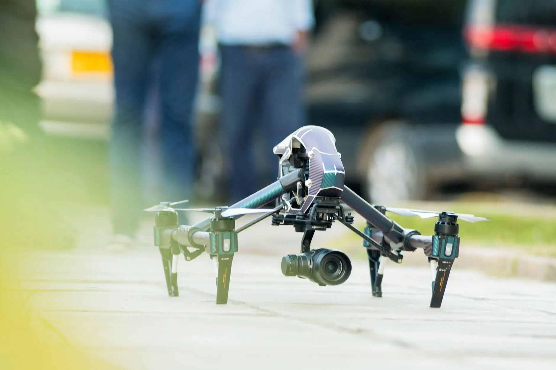
Drone with Thermal: OEM 640 LWIR Core Selection & Integration Guide
Drone with Thermal: OEM 640 LWIR Core Selection & Integration Guide
Building a drone with thermal imaging starts with choosing a camera core that fits the mission and the aircraft. Integrating a bare Long-Wave Infrared (LWIR) core gives unmanned aircraft system (UAS) manufacturers and payload developers control over optics, interfaces, processing and mechanical design. Costs and long-term supply still depend on the complete configuration and project volume.
A successful OEM integration needs more than a sensor: budget Size, Weight, and Power (SWaP) for the lens, interface board, wiring and enclosure, then validate electrical noise, vibration, video timing and thermal stability on the completed payload.
For the 640×512 uncooled Vanadium Oxide (VOx) cores compared here, the first decision is whether the mission requires thermal images or calibrated temperature data. The 8 μm CAMCUDA SuperMini 640 is a 50 Hz imaging-only core; the SuperMini 640T is the separate 30 Hz thermographic model. Their published sub-3.5 g mass excludes optics and interface boards.
The 12 μm CAMCUDA AeroMini is another integration option, with a published NETD of ≤30 mK at 25°C, F/1.0. Its non-radiometric version defaults to 60 Hz, with a 30 Hz factory option. This guide compares those roles and the optical, electrical, mechanical and software checks needed before deployment.
Table of Contents
- 👉 1. Uncooled LWIR Sensor Physics: VOx Arrays, Pixel Pitch & NETD Dynamics
- 👉 2. Airborne Optical Engineering: Athermal Lenses, IFOV & Johnson Criteria
- 👉 3. Production-Ready 640 LWIR Camera Cores: Comparative OEM Specifications
- 👉 4. Electrical Architecture: Power Rail Filtering, MIPI CSI-2, LVCMOS & USB Pipelines
- 👉 5. Micro-Gimbal Mechanical Integration, Center of Gravity & Thermal Dissipation
- 👉 6. Radiometric Temperature Measurement vs. Fast Dynamic Imaging Pipelines
- 👉 7. Embedded Edge AI: Deploying Computer Vision & TensorFlow Models on Thermal Feeds
- 👉 8. Deep-Dive OEM Integration FAQ
1. Uncooled LWIR Sensor Physics: VOx Arrays, Pixel Pitch & NETD Dynamics
When designing an airborne payload around an uncooled LWIR sensor, look beyond resolution. Pixel geometry, optics, detector response and processing all affect image quality and the payload budget. A microbolometer absorbs infrared radiation, producing a temperature change in its sensing element and a corresponding resistance change that the readout circuit measures. The cores discussed here have a published 8–14 μm spectral response.
Vanadium Oxide (VOx) vs. Amorphous Silicon (a-Si)
VOx and amorphous-silicon microbolometers are both used in uncooled thermal imaging. Material name alone does not establish sensitivity, response time or image quality; compare the complete detector, lens and processing configuration. LWIR imaging works without visible illumination, but humidity, fog, smoke composition and intervening vegetation can reduce useful contrast or obscure the target. Fast aircraft motion also requires validation of exposure, detector response, stabilization and end-to-end latency; no sensor specification guarantees sharp frames during every maneuver.
The Physics of Pixel Pitch: 8 μm vs. 12 μm
Moving from a 12 μm to an 8 μm pixel pitch reduces the active dimensions of a 640×512 array and changes the optical design trade-offs:
- ⚙️ Pixel Pitch & Optical Mass: An 8 μm 640×512 array has an active diagonal one-third smaller than a 12 μm array of the same resolution. A shorter focal length can therefore provide a similar field of view. Actual lens mass, barrel size and image quality still depend on the optical design, aperture and diffraction.
- ⚙️ Aperture & Sensitivity: Evaluate pixel pitch together with F-number, optical transmission and the published NETD conditions. The CAMCUDA SuperMini 640 / 640T specifies ≤40 mK at 25°C, F1.0; this does not establish a guaranteed mission range or temperature accuracy.
- A 12 μm core such as CAMCUDA AeroMini 640 offers 640 × 512 imaging with a published NETD of ≤30 mK at 25 °C, F/1.0. Evaluate sensitivity together with the selected lens, target contrast and operating conditions; NETD does not establish a guaranteed detection range or radiometric accuracy.
Noise Equivalent Temperature Difference (NETD) and Motion Artifacts
Low NETD can help distinguish small scene-temperature differences under the stated test conditions. It does not eliminate noise, motion blur or loss of target contrast. Non-Uniformity Correction (NUC) addresses pixel-response variation; shutter-based correction may briefly interrupt the image. Confirm the selected core and firmware behavior, then measure frame continuity and latency during flight-representative thermal changes.
2. Airborne Optical Engineering: Athermal Lenses, IFOV & Johnson Criteria
Lens selection is part of the airborne thermal design. Ambient temperature, airflow, vibration and mechanical tolerances can affect focus and contrast. Validate the selected lens and enclosure over the actual operating envelope instead of assuming that a nominal focal length or F-number establishes flight performance.
Athermalized Optical Design
Germanium and other infrared optical materials change refractive index with temperature, while lens barrels and spacers expand or contract. Athermal optical designs compensate for these effects within a specified range. SuperMini lists four F1.0 athermal lens options; confirm the chosen assembly and focus behavior. Do not assume every manual-focus lens fails in flight, or that every fixed-focus lens remains athermal across the complete aircraft environment.
Calculating Instantaneous Field of View (IFOV) and Target Resolution
Use Instantaneous Field of View (IFOV) to estimate pixel coverage at a chosen slant range. Ground Sample Distance (GSD) is a useful near-nadir, locally flat-ground approximation; oblique views require projection geometry. Neither calculation alone establishes whether a person, vehicle or inspection defect can be detected, recognized or measured:
IFOV (mrad) ≈ Pixel Pitch d (μm) / Focal Length f (mm)
Near-axis pixel footprint (m) ≈ IFOV (mrad) × Camera-to-target Range R (km)
- ⚙️ Wide-Angle Coverage (3.7 mm on an 8 μm core): The SuperMini lens table publishes a 90.0° × 68.2° FOV. The pitch/focal-length approximation gives an IFOV of 2.16 mrad; use the actual lens calibration for wide-angle edge coverage.
- ⚙️ Compact UAV Imaging (9 mm AeroMini, 12 μm pitch): The current product page publishes a 48.7° × 38.6° FOV. The pitch/focal-length approximation gives 1.33 mrad; the published lens FOV and a simplified pinhole estimate need not match exactly.
- ⚙️ Narrower Coverage (35 mm on a 12 μm core): The pitch/focal-length approximation gives 0.34 mrad, while AeroMini lists a 12.5° × 10.0° FOV for its 35 mm lens. More pixels on a distant target can help, but atmosphere, contrast, motion and task criteria still limit practical range.
| Johnson Criteria Task Category | Nominal Line Pairs Across Critical Target Dimension | Approximate Sampling Equivalent | Meaning Under Stated Test Conditions |
|---|---|---|---|
| Detection | 1 ± 0.25 line pairs | About 2 pixels | An object is distinguishable from the background. |
| Recognition | 4 ± 0.8 line pairs | About 8 pixels | A broad target class can be distinguished. |
| Identification | 6.4 ± 1.5 line pairs | About 13 pixels | Finer distinguishing features may be resolved. |
These classical Johnson values are nominal 50%-probability references for human observers; the pixel equivalents use a simplified two-samples-per-line-pair conversion. They are not flight acceptance criteria or AI accuracy guarantees. The thermal imaging calculator can help compare resolution, pixel pitch, focal length, target dimensions and working distance as a geometric planning step. Validate the result with the actual optics and mission conditions; see also our outdoor field thermal imaging integration guide.
3. Production-Ready 640 LWIR Camera Cores: Comparative OEM Specifications
When selecting a core, compare the complete assembly, power supplies, optical configuration and host interface. The current product roles below are the compact CAMCUDA SuperMini 640 / 640T family and the CAMCUDA AeroMini 640 family. Confirm lens, board, firmware and supplied items for the exact configuration before finalizing the BOM.
CAMCUDA SuperMini 640 / 640T Ultra-Light LWIR Thermal Camera Module
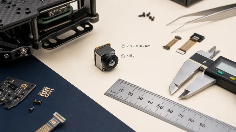
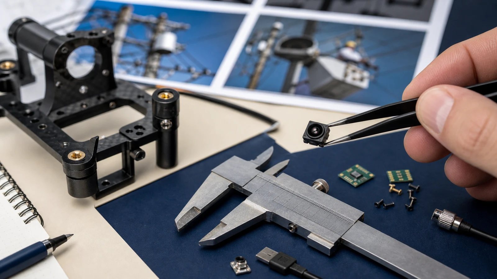
The CAMCUDA SuperMini 640 / 640T series uses a 640×512 uncooled VOx detector with an 8 μm pixel pitch. Published bare-core dimensions are 13×13×13.4 mm and mass is less than 3.5 g, excluding optics and expansion boards. Choose the 50 Hz imaging-only 640 or the separate 30 Hz thermographic 640T. Lens, interface, supplied items and quantity require configuration review and quotation before an order is accepted.
| Specification | CAMCUDA SuperMini 640 (Imaging Only) | CAMCUDA SuperMini 640T (Thermographic) |
|---|---|---|
| Resolution & Pitch | 640 × 512, 8 μm VOx Uncooled FPA | 640 × 512, 8 μm VOx Uncooled FPA |
| Output Frame Rate | 50 Hz (imaging only; no temperature measurement) | 30 Hz (thermographic model) |
| NETD Sensitivity | ≤40 mK @ 25°C, F1.0 | ≤40 mK @ 25°C, F1.0 |
| Temperature Range | N/A (Imaging only) | −20°C to +150°C and 100°C to +650°C |
| Digital Video Paths | 8-bit LVCMOS / BT.656, 2-lane MIPI | CDS3 image + temperature; 2-lane MIPI with mode-specific layout |
| Core Dimensions & Mass | 13.0 × 13.0 × 13.4 mm | <3.5 g; excludes optics and expansion boards | |
| Power Consumption | ≤0.5 W typical core power at 25°C, excluding expansion boards; complete payload power differs | |
| Hardware Connector | Hirose DF40C-30DP-0.4V(51), 30-pin; use matched mating orientation and complete pin table | |
| Athermal Lens Options |
3.7 mm (90.0° × 68.2°, 2.16 mrad) 6.1 mm (46.6° × 37.6°, 1.31 mrad) 8.7 mm (40.0° × 32.2°, 0.92 mrad) 11.0 mm (24.9° × 20.0°, 0.73 mrad) |
|
CAMCUDA AeroMini 640 LWIR Thermal Camera Core
The CAMCUDA AeroMini 640 uses a 640×512 uncooled VOx detector with a 12 μm pitch and published NETD of ≤30 mK at 25°C, F/1.0. The 9 mm non-radiometric configuration provides 60 Hz by default or a 30 Hz factory option and does not measure temperature. Published module power is <0.5 W at 25°C; dimensions of 21×21×28 mm and mass <20 g exclude the lens and flange. Select the USB + CVBS + MIPI tailboard, Type-C + CVBS tailboard, or both-board kit as appropriate and verify the complete assembly.
The separate 25 Hz radiometric version is currently out of stock, with 9/13/18 mm availability enquiries only and no online purchase, pre-order or deposit. The table below retains generic 12 μm optical-planning examples; its six focal lengths are not an AeroMini SKU list.
| Illustrative Focal Length | Geometric FOV (H × V) | Approximate IFOV | 0.5 m Target / 3 Pixels | 0.5 m Target / 12 Pixels | 0.5 m Target / 24 Pixels | Configuration Note |
|---|---|---|---|---|---|---|
| 4.1 mm | Generic 12 μm wide-angle example: 86.2° × 73.7°, IFOV 2.93 mrad. Values are geometric estimates, not an AeroMini lens specification. | Planning example only | ||||
| 4.9 mm | 76.2° × 64.2° | 2.45 mrad | 68.1 m | 17.0 m | 8.5 m | Planning example only |
| 9.0 mm | 46.2° × 37.7° | 1.33 mrad | 125.0 m | 31.2 m | 15.6 m | Planning example only |
| 13.0 mm | 32.9° × 26.6° | 0.92 mrad | 180.6 m | 45.1 m | 22.6 m | Planning example only |
| 19.0 mm | 22.9° × 18.4° | 0.63 mrad | 263.9 m | 66.0 m | 33.0 m | Planning example only |
| 35.0 mm | 12.5° × 10.0° | 0.34 mrad | 486.1 m | 121.5 m | 60.8 m | Planning example only |
*Geometric examples for a 640×512, 12 μm array and a 0.5 m target width. FOV = 2 × atan(sensor dimension / 2f); IFOV ≈ pitch / focal length; range = target width / (pixel count × IFOV in radians). The 3/12/24-pixel columns are illustrative sampling budgets, not validated human detection, recognition or identification distances. Use the stated pixel-count assumptions when comparing calculations; calculator presets may differ. Lens distortion, target orientation, contrast, atmosphere and processing are excluded; confirm actual lens options separately.
4. Electrical Architecture: Power Rail Filtering, MIPI CSI-2, LVCMOS & USB Pipelines
Drone power distribution can expose the payload to switching noise from Electronic Speed Controllers (ESCs), motor-current transients and RF coupling. Design the camera power path for the actual input range, transient environment and grounding arrangement, then measure noise and image quality with motors and transmitters operating.
Power Supply Ripple and Decoupling Requirements
Microbolometer readout electronics measure small detector-resistance changes. Supply noise and ground coupling can introduce image artifacts or degrade sensitivity. The following rail limits and table apply to the SuperMini bare core; they are not a universal power specification for AeroMini or an optional expansion board.
- ⚙️ SuperMini 640 / 640T Multi-Rail Layout: The bare core requires MAIN_POWER at 3.8–5.2 V (5.0 V typical), a +3.3 V rail at 3.28–3.32 V and a +1.8 V rail at 1.78–1.82 V. Published noise limits are 10 mV p-p on the first two rails and 1 mV RMS (1 Hz–50 kHz) on +1.8 V. Use the SuperMini 30-pin connector definition and power requirements and sequencing; t1, t2 and t3 must each exceed 200 μs, and restart requires more than 5 seconds after power-off.
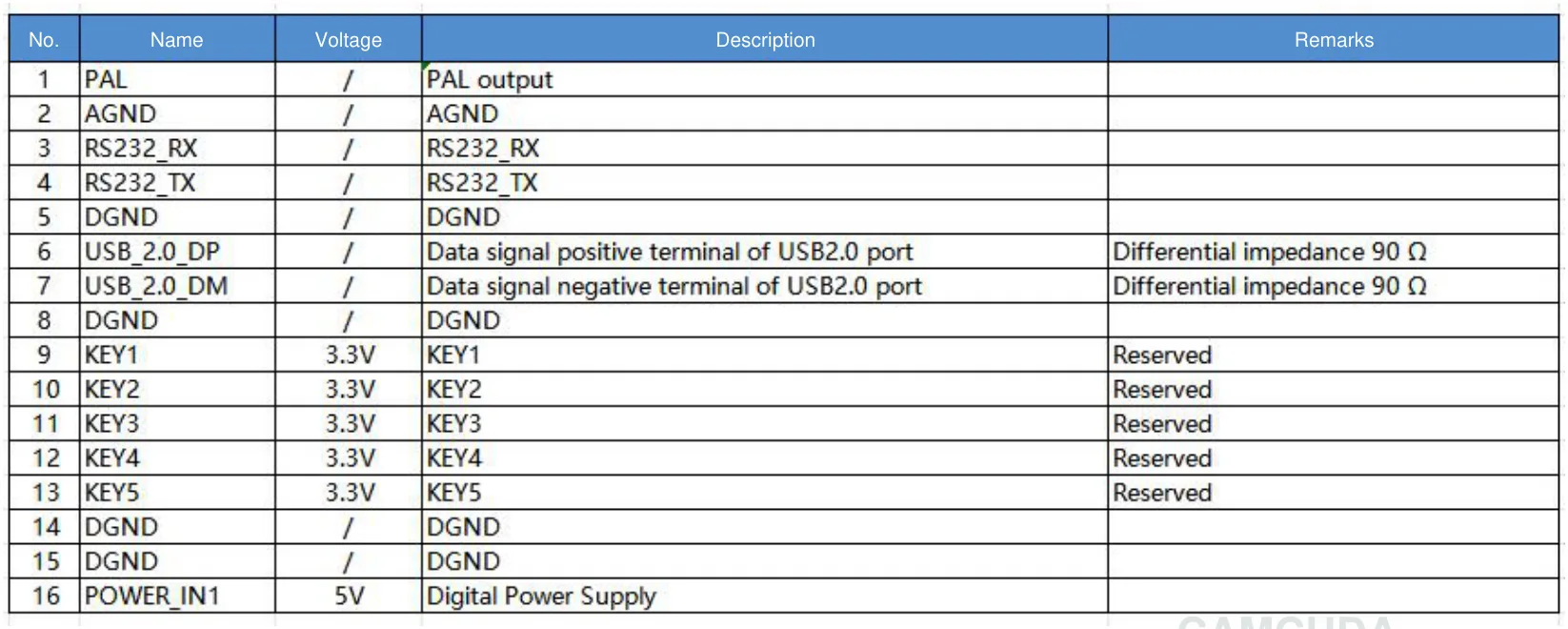
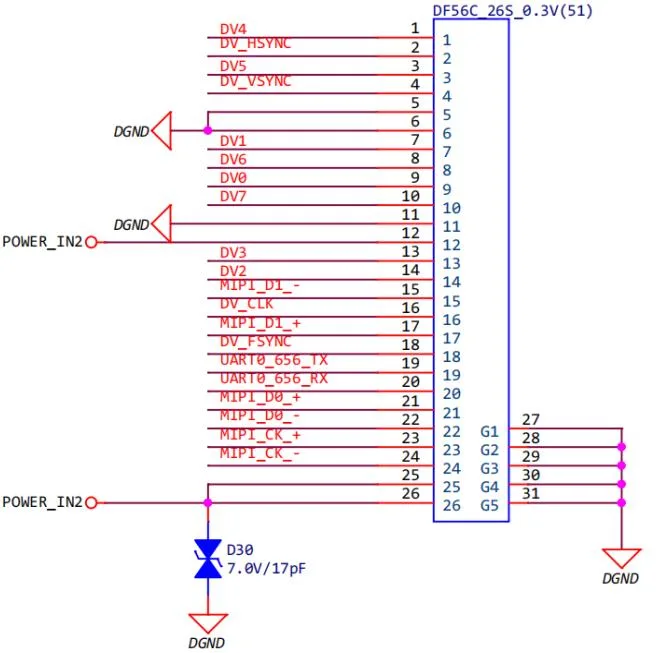
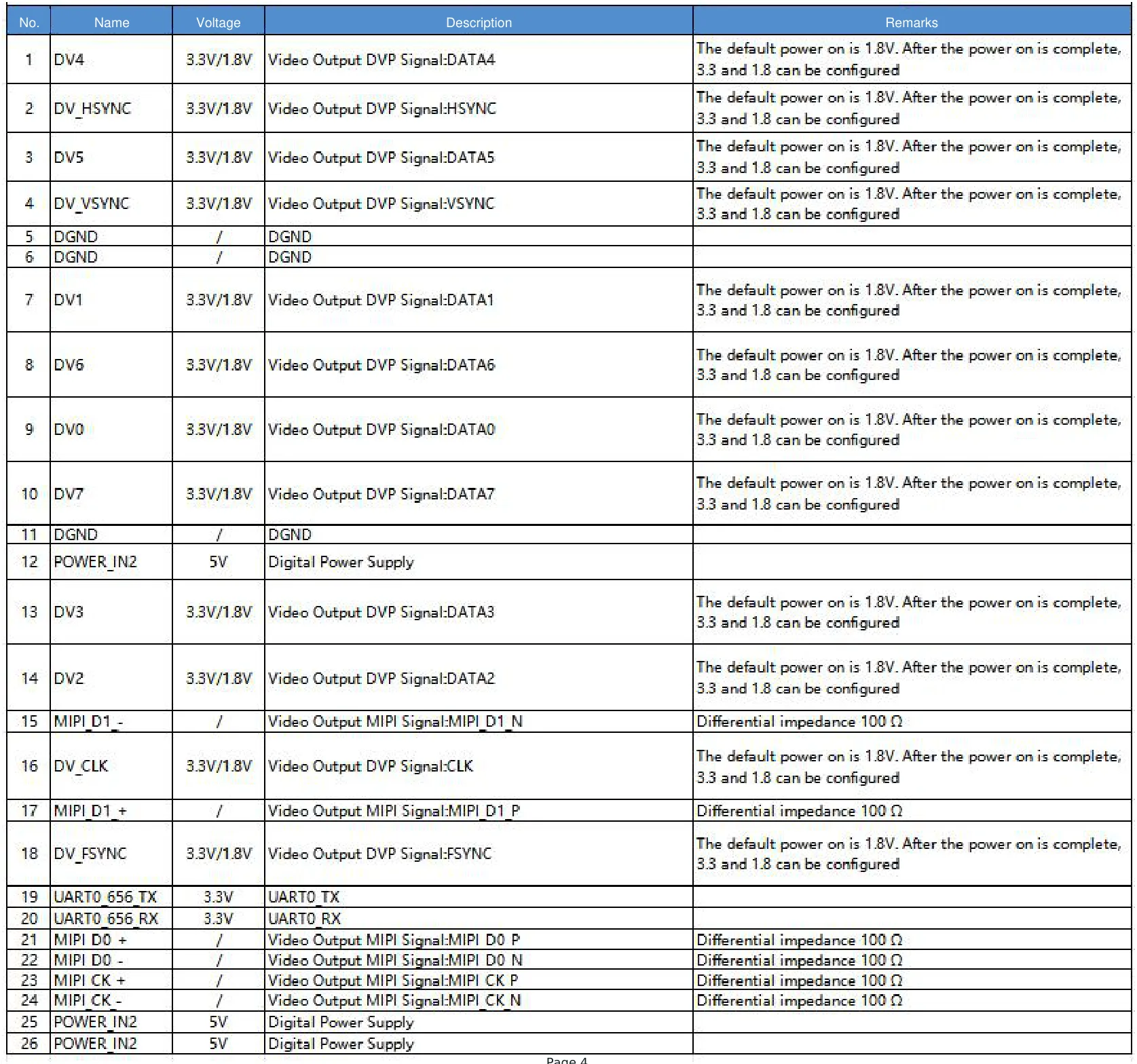
- ✅ AeroMini Board-Specific Power: The illustrated 16-pin USB/CVBS diagram and signal table specify POWER_IN1 as 5 V; the 26-pin MIPI/DVP diagram and signal table specify POWER_IN2 as 5 V. Do not apply 12 V to these pins or connect them directly to a flight battery. The family-level 5 V/12 V entry is board-dependent. These diagrams do not define the Type-C board or SuperMini wiring; confirm the supplied board revision and mating orientation.
| SuperMini Bare-Core Path | Published Electrical Specification | OEM Aerial Integration Requirement |
|---|---|---|
| MAIN_POWER | 3.8–5.2 V, typical 5.0 V | 10 mV p-p maximum noise; select decoupling for the actual carrier design. |
| +3.3 V Digital Rail | 3.28–3.32 V | 10 mV p-p maximum noise; validate regulation under load. |
| +1.8 V Analog Rail | 1.78–1.82 V | 1 mV RMS maximum (1 Hz–50 kHz); use a supply design that meets this limit. |
| Digital Video | 8-bit LVCMOS; 2-lane MIPI | 640: BT656 / MIPI · 640T: CDS3 / MIPI. Match receiver format and timing; BT656 and MIPI are not simultaneous. |
| Serial Control | UART, 1.8 V logic level | TX/RX are referenced to the core. Verify voltage compatibility; use level translation where required. |
| USB / CVBS Video | USB 2.0 D+/D−; CVBS analog pin | CVBS requires an external video-buffer IC. Confirm USB board, firmware, format and host support. |
Digital Video Pipeline Selection
Picking your video interface defines your companion computing architecture:
- ⚙️ MIPI CSI-2 (Camera Serial Interface): SuperMini specifies two MIPI data lanes at 216 Mbps per lane and a 108 MHz clock lane. The receiver must match the actual mode, timing and data layout; MIPI transport does not make a camera automatically compatible with a Jetson, Raspberry Pi or other host. Route the differential pairs to the module and receiver requirements, validate the PCB stack-up and signal integrity, and implement the required driver. SuperMini BT656 and MIPI cannot operate simultaneously.
- ⚙️ 8-bit LVCMOS / BT.656: SuperMini publishes a 45 MHz 8-bit LVCMOS path with progressive RAW image data and no pseudocolor on LVCMOS. Match the clock and synchronization to the chosen mode. The 640T CDS3 path carries YUV422 image and temperature data; confirm the actual firmware timing because the manual summary and detailed CDS3 synchronization description differ.
- ✅ USB Integration: The optional SuperMini TMS6102V100F022 board provides a 4-pin USB interface for both variants and uses 5 V USB_VBUS. AeroMini offers separate USB + CVBS + MIPI and Type-C + CVBS tailboards; its USB-SDK.zip resource contains Linux drivers, examples and the SDK for AeroMini. Confirm the exact board, firmware, pixel format, operating system and host receiver before committing to either family. A USB connector alone does not establish UVC enumeration or temperature-data support; refer to the USB-IF specifications where applicable.
- ✅ Analog CVBS Video: AeroMini lists PAL/NTSC analog video with availability dependent on the selected board. SuperMini CVBS requires an external video-buffer IC. Confirm the electrical level, format and transmitter compatibility, and measure end-to-end latency on the completed system instead of assuming a sub-20 ms result.
For an exhaustive routing and grounding checklist, review our in-depth carrier board guide covering IR camera module drone OEM integration checks.
5. Micro-Gimbal Mechanical Integration, Center of Gravity & Thermal Dissipation
Payload balancing connects the mechanical design to gimbal performance. Additional mass and its distance from the rotation axis increase rotational inertia; cable forces, lens mass and enclosure geometry also matter. Check center of gravity and motor margin for the complete payload, including the selected lens and board.
Minimizing Gimbal Motor Load with <3.5 g Cores
The CAMCUDA SuperMini 640 / 640T has a published 13.0 × 13.0 × 13.4 mm bare-core envelope and mass under 3.5 g, excluding optics and expansion boards. These values are a starting point for a small gimbal budget; include all supplied and integrator-added parts before choosing motors and mounts.
- ✅ Dual-Sensor Payloads: A compact core can leave room for a visible camera, but verify lens clearances, boresight alignment, wiring and the combined mass against the actual gimbal envelope.
- ✅ Gimbal Tuning: For a point-mass approximation, I = m · r²; mass farther from the axis increases inertia strongly. Balance the assembled payload and tune the controller against measured resonances. Core mass alone does not establish a safe control-loop frequency or prevent oscillation.
- ✅ Complete Payload Mass Budget: Core mass is only one part of the aircraft budget. Count the lens, interface board, harness, enclosure, optical window, mounts and stabilization hardware, and weigh the completed payload before assessing flight endurance or a sub-250 g design.
Thermal Dissipation and Grounding in Sealed Gimbals
SuperMini lists ≤0.5 W typical core power at 25°C, excluding expansion boards; AeroMini lists <0.5 W at 25°C. Interface boards and the rest of the payload add power and heat. Even low-power cores can experience thermal gradients in a sealed gimbal, so validate warm-up, steady operation and changing airflow in the complete assembly.
- ⚙️ Controlled Heat Paths: Design a heat path consistent with the manufacturer’s mounting guidance. Check thermal-pad compression, mounting stress, clearances and detector stability before coupling the housing to the gimbal structure. Verify performance in the final enclosure rather than assuming a particular pad conductivity will solve every thermal problem.
- ⚙️ Grounding & EMI: Plan signal returns, shielding and chassis bonds for the actual board and airframe. Avoid ground loops and test with motors, transmitters and switching supplies active. Do not assume directly bonding every camera housing to a shared ground is appropriate.
Use the SuperMini bare-core dimensional drawing for the stated core envelope only; its dimensions exclude the lens and expansion board. AeroMini’s published 21×21×28 mm dimensions exclude lenses and flanges, and its separate 3D preview represents the 7 mm model, not the selected 9 mm assembly. Request matched lens/board assembly drawings and mounting details through the technical support portal before releasing the gimbal design.
6. Radiometric Temperature Measurement vs. Fast Dynamic Imaging Pipelines
Before you lock down your BOM, make sure you know exactly what your software needs: are you building for contrast-enhanced tactical vision or calibrated thermographic radiometry?
Imaging Cores: SuperMini 640 at 50 Hz & AeroMini at 60/30 Hz
For search-and-rescue video, navigation or perimeter observation, evaluate useful contrast, frame continuity and latency. The SuperMini 640 is imaging-only at 50 Hz. The non-radiometric AeroMini defaults to 60 Hz, with 30 Hz selected as a factory configuration; neither provides calibrated temperature measurement.
- ✅ Frame Rate & Motion: Higher output rates can provide more frequent visual updates, but image sharpness and pilot feedback also depend on detector response, exposure, transport, processing and display delay. Measure the complete path under the intended flight conditions.
- ✅ Image Processing: Contrast enhancement and palettes can improve visual presentation but do not create calibrated temperature values. Check the processing and output formats supported by the selected mode. Standard AeroMini does not provide the RAW or minimally processed output described in its FAQ; that requirement needs a separate customization assessment.
Calibrated Radiometric Cores (CAMCUDA SuperMini 640T)
If your drone is inspecting solar farms, checking high-voltage utility splices, or surveying industrial roofs, you need calibrated numbers, not just relative contrast.
- ⚙️ Published Measurement Ranges: SuperMini 640T lists −20°C to +150°C and +100°C to +650°C, with published typical accuracy of ±2°C or ±2% of the reading at ambient −20°C to +60°C. Confirm the mode and calibration for the ordered unit. These are thermographic 640T specifications, not imaging-only 640 specifications.
- ⚙️ Temperature Data Layout: The 640T MIPI format uses RAW8 transport received as (1280 × 2) × 512 bytes. Reassemble adjacent low-byte-first pairs into 16-bit words; each line contains 640 image words followed by 640 temperature words. The detector remains 640×512. Apply the manual’s ND or HD conversion formula for the actual output mode. Validate target fill, emissivity, reflected apparent temperature and atmospheric effects for the measurement task; receiving temperature words alone does not establish report accuracy or standards compliance.
7. Embedded Edge AI: Deploying Computer Vision & TensorFlow Models on Thermal Feeds
Thermal images can feed detection or tracking models on a companion processor. These camera cores do not establish a complete autonomous perception system by themselves. Select the processor and model for the required task, and validate detection accuracy, power, frame loss and latency using representative airborne data.
Zero-Copy Pipeline Integration
Reducing unnecessary memory copies can improve an embedded video pipeline. Where the capture driver and processing stack support it, use mechanisms such as V4L2 DMA-BUF import/export to share buffers between components. USB or MIPI alone does not guarantee zero-copy capture, direct GPU access or near-zero CPU use. Profile capture, preprocessing, inference and display on the exact host, firmware and output mode.
Deploying TensorFlow Deep Learning Models on LWIR Streams
A thermal detector measures infrared scene information; a displayed color palette is a visualization of that signal. Train and validate the model with the same image format and processing used during deployment, rather than treating palette colors as ordinary scene RGB.
- ⚙️ Model Training: Use representative thermal datasets with frameworks such as TensorFlow. Include relevant ranges, viewpoints, weather, target contrast, motion and sensor artifacts, and evaluate on separate flight data. Synthetic blur or noise can supplement testing but does not reproduce all atmospheric or detector effects.
- ⚙️ Quantization & Profiling: Evaluate INT8 or FP16 execution on a compatible inference stack, checking accuracy after conversion. Throughput depends on the model, input layout, preprocessing, processor and power mode; a 640×512 source does not guarantee 50 Hz inference or sub-15 ms latency.
8. Deep-Dive OEM Integration FAQ
Why are OEM payload developers moving toward standalone thermal camera modules rather than locked off-the-shelf thermal drones?
How do I determine whether my thermal drone payload needs an imaging-only core or a radiometric core?
How can I manage SWaP (Size, Weight, and Power) constraints when adding a thermal camera to a small drone?
What are the primary electrical noise hazards when routing power to an uncooled VOx microbolometer core on a drone?
How does ambient convective airflow affect thermal imaging performance during flight, and how can it be mitigated?
Technical author: Daniel · Hardware Support
Sales contributors: Vivian, Lena and Sophie
📚 References & Further Reading
- Industry Standard: USB-IF Document Library (Universal Video Class & Communication Specifications)
- Machine Learning Framework: TensorFlow (Edge AI Inference & Neural Model Optimization)
- Related Integration Guide: IR Camera Module Drone OEM Integration Checks & Carrier PCB Best Practices
- Application Reference: Outdoor Field Thermal Imaging Payloads: Defense, SAR & Industrial Systems
- OEM Engineering Support: CAMCUDA Technical Support, Custom Pinout Inquiries & 3D Step Files