DJI Drones with Thermal Camera: Enterprise Models vs. Custom OEM Payloads
DJI Drones with Thermal Camera: Enterprise Models vs. Custom OEM Payloads
An industrial engineering analysis comparing closed commercial aerial thermography platforms against modular, open-architecture LWIR sensor integrations for unmanned edge systems.
Technical author: Daniel · Hardware Support
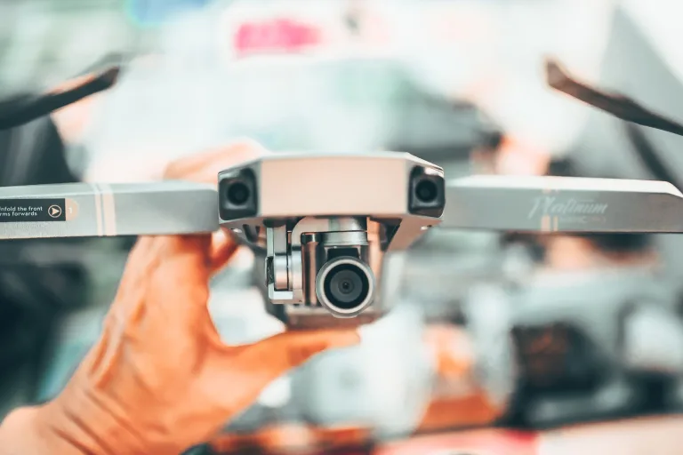
Thermal imaging has transformed unmanned aerial vehicle (UAV) missions across power grid maintenance, structural integrity evaluation, public safety, search and rescue (SAR), and precision agriculture. When deploying DJI drones with thermal camera packages, hardware leads and procurement teams generally lean on turnkey commercial birds—think the DJI Mavic 3 Enterprise Thermal (M3T), Matrice 30T, or a Matrice 350 RTK hauling a Zenmuse H20T or H30T multi-sensor gimbal. These ready-to-fly platforms package visible-light electro-optical (EO) sensors alongside long-wave infrared (LWIR) microbolometers inside proprietary, multi-axis stabilized payloads, giving operators fast deployment straight out of the flight case.
Here’s the deal: as industrial UAV missions push deeper into autonomous flight routines, real-time edge computing, and classified or specialized profiles, the hard programmatic walls of closed commercial platforms hit you fast. Closed-source flight controllers, encrypted telemetry buses, non-swappable fixed optics, and brutal fleet repair turnaround times create massive operational friction for original equipment manufacturers (OEMs), robotics integrators, and defense technologists.
In the shop, when you need low-latency direct memory access to raw thermal frames or you are trying to cut structural payload grams down to squeeze an extra eight minutes of flight time out of a 6S LiPo pack, an off-the-shelf commercial drone hits a wall. This technical blueprint breaks down the exact trade-offs between turnkey enterprise thermal platforms and custom, modular low-SWaP (Size, Weight, Power, and Cost) OEM LWIR camera core integrations built directly on custom airframes and embedded compute boards.
Whether you are designing sub-250g tactical throwables, automating utility sub-station rovers, or integrating neural networks on companion computers, understanding the silicon, optics, and data buses under the hood is critical to making the right architectural call.
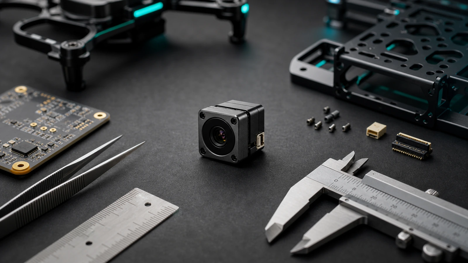
Table of Contents
- 👉 DJI Drones with Thermal Camera vs. Modular OEM Architectures
- 👉 Sensor Physics and LWIR Detection in Drone Operations
- 👉 SWaP-C Optimization in Aerial Thermal Systems
- 👉 Digital Video Pipelines, Edge AI, and Interface Integration
- 👉 Optical Selection: IFOV, Athermalization, and Target Discrimination
- 👉 Featured Industrial OEM Thermal Camera Modules
- 👉 Integration Engineering: Power, Thermal Dissipation, and Signal Routing
- 👉 Comprehensive Engineering FAQ
DJI Drones with Thermal Camera vs. Modular OEM Architectures
Turnkey enterprise thermal UAV platforms deliver tightly coupled hardware and software environments. A commercial platform packages the airframe, proprietary battery management system (BMS), encrypted digital RF link, multi-sensor stabilized gimbal, and dedicated ground control station (GCS) software into a single unified product. For municipal first responders, structural fire crews, and standard roofing surveys, this end-to-end integration works right out of the box without requiring specialized bench engineering.
Turnkey Ecosystem Constraints
Look at the limitations once you try to customize or scale an enterprise fleet under rugged conditions:
- ⚠️ Proprietary Payload Interfaces: Integrated thermal gimbals use closed, encrypted hardware and software protocols (such as proprietary flat flex ribbons or specialized SkyPort lock rings). This architecture blocks you from swapping detectors, modifying the optical bench, or integrating custom analytical lenses on compact and mid-tier enterprise birds.
- ⚠️ Fixed Optical Paths: Built-in commercial LWIR payloads lock you into a single, fixed wide-angle focal length (routinely 9 mm to 13.5 mm equivalent on 640×512 arrays). That wide field-of-view forces pilots to fly dangerously close to high-voltage transmission lines, substation insulators, or active flare stacks to get enough pixels on target.
- ⚠️ Closed Sensor Data Planes: Turnkey video pipelines feed directly into hardware H.264/H.265 compression encoders before broadcasting across proprietary transmission links. This lossy compression strips out frame-by-frame 14-bit or 16-bit radiometric metadata and introduces 120–200 ms of latency—making low-latency, onboard autonomous machine vision tracking almost impossible.
- ⚠️ Lifecycle Economics and High Total Cost of Ownership: Snapping a gimbal arm on an integrated commercial drone usually means grounding the entire airframe, sending it to a certified depot, and paying steep repair bills. For teams running dozens of drones in remote or GPS-denied environments, high unit replacement costs elevate total operational expenditure.
Modular OEM Payload Architectures
Developing custom thermal payloads using bare, uncooled long-wave infrared cores alongside open-standard flight stacks (like PX4 Autopilot, ArduPilot, and MAVLink telemetry) gives engineering teams full control:
- ✅ Direct Edge Interfacing: Uncompressed digital thermal video feeds (via 2-lane MIPI CSI-2, parallel LVCMOS, or native USB) route straight into companion microcomputers like the NVIDIA Jetson Orin Nano, Raspberry Pi CM4, or custom FPGA vision processors. This architecture enables deep learning models at the structural edge, aligning with modern industrial edge computing architectures.
- ✅ Interchangeable Optics: System designers can configure precise optical assemblies—from ultra-wide 3.7 mm lenses for close-in indoor obstacle avoidance to tight 11 mm or 19 mm athermalized lenses for high-altitude utility surveys. For a systematic approach to matching interfaces and spatial metrics, refer to our thermal camera core selection and integration checklist.
- ✅ Total SWaP-C Optimization: Stripping unnecessary plastic casings, heavy multi-sensor brackets, and redundant interface boards lets you cut payload mass down to bare grams, directly extending airtime.
Sensor Physics and LWIR Detection in Drone Operations
Aerial thermal imaging operates inside the Long-Wave Infrared (LWIR) atmospheric transmission window, spanning 8 μm to 14 μm. Unlike short-wave (SWIR) or mid-wave (MWIR) infrared systems that require bulky, power-thirsty cryogenic Stirling coolers, industrial aerial drones rely on uncooled Vanadium Oxide (VOx) microbolometer focal plane arrays (FPAs). VOx microbolometers are preferred for airborne payloads thanks to their solid-state reliability, low module-level power consumption (confirm the selected core and interface-board configuration), resistance to high-frequency motor vibration, and instant boot-up times.
The microbolometer array absorbs incoming infrared radiation focused through an athermalized optical lens. As each pixel absorbs radiant energy, its internal temperature shifts, altering its electrical resistance. An underlying Read-Out Integrated Circuit (ROIC) measures these resistance differentials across the entire array, converting thermal energy into digitized radiometric temperature values and high-contrast grayscale imagery.
Critical Radiometric Performance Parameters
Evaluating an LWIR thermal sensor for aerial deployment involves four foundational engineering parameters:
- Noise Equivalent Temperature Difference (NETD): Expressed in millikelvins (mK), NETD represents the smallest temperature differential the sensor can resolve above its electronic noise floor. High-performance enterprise cores achieve an NETD ≤ 40 mK at 25°C with an F1.0 optical assembly. A lower NETD ensures clear target discrimination in low-contrast conditions, such as maritime search operations, navigation through smoke, or overcast building envelope audits.
- Pixel Pitch (Microns): The physical spacing between individual microbolometer pixel centers. Historically, industrial cores used 17 μm or 12 μm pixel pitches. Contemporary micro-miniature cores utilize an 8 μm pixel pitch. An 8 μm pixel pitch cuts focal length and optical track requirements in half while maintaining high spatial resolution, substantially decreasing payload mass.
- Non-Uniformity Correction (NUC) and Scene-Based Drift Management: Drones experience rapid ambient thermal fluctuations during vertical ascent and high-speed transit. These ambient shifts create thermal gradients across the core housing, causing fixed-pattern noise (FPN). Advanced OEM modules combine quick shutter-based calibration with continuous Scene-Based Non-Uniformity Correction (SBNUC) and Digital Detail Enhancement (DDE) filtering to deliver a clean image stream without frozen frames during critical flight maneuvers.
- Radiometric Temperature Calibration: The CAMCUDA SuperMini 640T is the 30 Hz thermographic model, with published measurement ranges of −20°C to +150°C and 100°C to +650°C. Its CDS3 and documented MIPI output carry image and temperature data. These capabilities do not apply to the imaging-only SuperMini 640. AeroMini has a separate 25 Hz radiometric version offered by availability enquiry; its published range is −20°C to +550°C, with interface, accuracy and RAW format to be confirmed.
SWaP-C Optimization in Aerial Thermal Systems
Size, Weight, Power, and Cost (SWaP-C) dictate the operational viability of any airborne sensor integration. On multirotor airframes, total airborne mass directly influences hover power requirements and battery discharge rates. Every additional 10 grams of payload mass decreases flight endurance non-linearly, requiring increased motor thrust and accelerating battery depletion.
The CAMCUDA AeroMini 640 is the configurable OEM reference in this comparison: its published 21 × 21 × 28 mm dimensions and <20 g weight exclude the lens and flange. The smaller CAMCUDA SuperMini 640 measures 13 × 13 × 13.4 mm and weighs <3.5 g as a bare core, excluding lens, flange and expansion board. Both provide 640 × 512 imaging, but these module figures are not complete payload weights. AeroMini lists <0.5 W typical module power at 25°C; SuperMini lists ≤0.5 W typical core power excluding its expansion board. Budget the optics, interface board, harness, gimbal and host computer separately, then measure power and flight endurance on the assembled system.
| Payload Architecture Class | Module / Payload Mass | Power Reference | Target Airframe Envelope | Primary Integration Application |
|---|---|---|---|---|
| SuperMini 640 Bare Core | <3.5 g; excludes lens, flange and expansion board | ≤0.5 W typical core; expansion board excluded | Sub-250g Micro-Drones, FPV | Tactical reconnaissance, confined space inspection |
| AeroMini 640 Configurable OEM Core | <20 g; excludes lens and flange | <0.5 W typical module at 25°C; kit may differ | UAV payloads; verify complete assembly mass | Automated perimeter security, robotics, Edge AI |
| Turnkey Commercial Gimbal | 120 g – 850 g | 5.0 W – 18.0 W | Enterprise Heavy Platforms | Manual pilot inspection, standard utility audits |
Digital Video Pipelines, Edge AI, and Interface Integration
Commercial turnkey drones compress thermal sensor data before transmission to the pilot ground station, limiting low-latency automated analysis. In contrast, custom OEM integrations allow engineers to route native, uncompressed digital video directly into companion computing boards for real-time edge processing.
Physical Digital Video Interfaces
- ⚙️ 2-Lane MIPI CSI-2: The industry standard for embedded vision. MIPI CSI-2 pipes uncompressed raw thermal frames directly into the host processor’s memory buffer using Direct Memory Access (DMA), sidestepping CPU overhead entirely.
- ⚙️ 8-Bit LVCMOS / BT.656: A parallel digital bus built for custom FPGA integration, specialized digital signal processors (DSPs), and hardware video transmitters requiring zero-jitter timing and ultra-low latency.
- ⚙️ USB Video Class (UVC): Provides plug-and-play cross-platform compatibility across Linux (V4L2), ROS/ROS2, and Windows platforms. For enterprise procurement criteria across these interfaces, review our thermal camera suppliers OEM RFQ checklist.
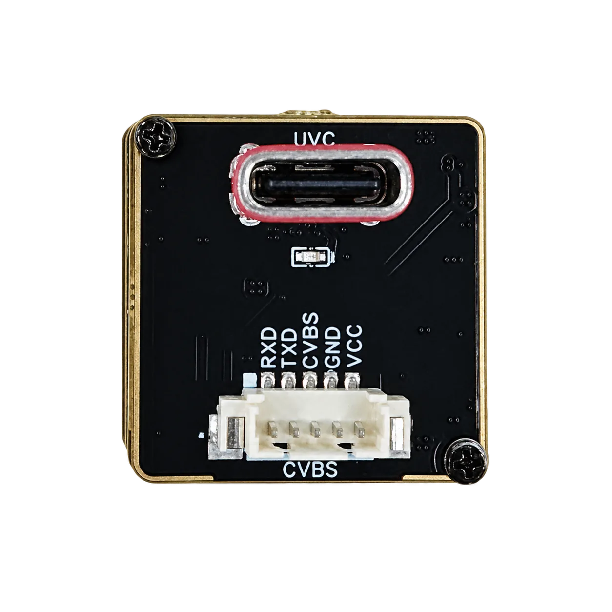
- ⚙️ CVBS Analog Composite: Delivers zero-latency analog video streams for FPV tactical downlinks and legacy mission equipment. When routing analog signals in high-EMI drone airframes, refer to our comprehensive guide on CVBS thermal camera module analog video integration.
Check the selected output path: This interface overview is not a guarantee that either featured module supports every listed mode or host. AeroMini outputs and serial buses depend on the selected tailboard and firmware. For SuperMini, BT656 and MIPI cannot operate simultaneously, the bare-core UART uses 1.8 V logic, and CVBS requires an external video-buffer IC. Confirm the USB class, pixel format, drivers and measured end-to-end latency for the ordered configuration.
AeroMini host-integration resources: The product FAQ identifies USB-SDK.zip as the source of Linux drivers, examples and the SDK. The public AeroMini technical documentation folder also lists CAMCUDA_AeroMini_640_USB_User_Manual_EN.pdf and the CV Serial port folder for control-interface documentation. Match these resources to the selected interface board, firmware, video format, frame rate and host software before integration.
Hardware Serial Control Buses
For industrial monitoring architectures and automated infrastructure security—such as security ecosystems designed by Bosch Security Systems—camera control relies on robust serial communication interfaces:
- ⚙️ RS-422 / RS-485: Differential transmission standards that provide high noise immunity across long wiring runs routed near high-RPM brushless motors and switching electronic speed controllers (ESCs).
- ⚙️ 1.8V / 3.3V Low-Voltage UART: Direct serial communication for integration with companion microcontrollers, open-source flight controllers, and embedded computing platforms.
Optical Selection: IFOV, Athermalization, and Target Discrimination
Selecting the appropriate thermal lens configuration involves balancing Field of View (FOV) against spatial resolution at defined operational stand-off distances. Fixed turnkey camera lenses cannot be swapped for specific mission profiles, making modular OEM configurations advantageous for specialized operations.
Instantaneous Field of View (IFOV) Calculation
IFOV estimates the angular sampling interval of one detector pixel. With pixel pitch in μm and focal length in mm, the small-angle expression below gives milliradians per pixel. It does not establish the minimum resolvable feature or a validated detection range.
IFOV (mrad) = Pixel Pitch (dp in μm) / Focal Length (f in mm)
Use the CAMCUDA Thermal Imaging Calculator to compare approximate IFOV, geometric field coverage and target pixel sampling for the selected lens and working distance. Its DRI estimates retain the 1.5 / 6 / 12 pixel thresholds for the selected target dimension; they do not guarantee field detection, recognition, identification or temperature-measurement accuracy. The table below reproduces the SuperMini manual’s published F1.0 lens FOV and IFOV values. A simple rectilinear calculation can differ from published lens FOV, so confirm the final optical assembly rather than changing the model to force agreement. UAV altitude alone is not the working distance for an oblique view.
| Focal Length | Aperture | Published SuperMini HFOV × VFOV | Published IFOV | Illustrative Application |
|---|---|---|---|---|
| 3.7 mm | F1.0 | 90.0° × 68.2° | 2.16 mrad | Close-proximity indoor inspection, FPV navigation |
| 6.1 mm | F1.0 | 46.6° × 37.6° | 1.31 mrad | Broad-area search and rescue (SAR), agricultural mapping |
| 8.7 mm | F1.0 | 40.0° × 32.2° | 0.92 mrad | Solar farm fault detection, commercial roof inspection |
| 11.0 mm | F1.0 | 24.9° × 20.0° | 0.73 mrad | High-voltage utility lines, long-distance stand-off security |
Optical Athermalization in Flight
LWIR optical elements are manufactured using optical-grade Germanium or Chalcogenide glass. Germanium features a high thermal index coefficient (∂n/∂T), causing optical defocusing during the rapid temperature changes typical of drone ascents and descents. Industrial UAV lenses must be mechanically or optically athermalized to maintain sharp focus across operating temperatures from −40°C to +85°C without requiring continuous motorized refocusing.
Featured Industrial OEM Thermal Camera Modules
For engineering teams comparing DJI drones with thermal camera packages against custom OEM payloads, AeroMini 640 is the primary configurable integration option here. SuperMini 640 is the same-resolution, smaller bare-core comparison. Both families are currently featured; confirm the selected model, lens, interface and availability before ordering. These are components for an engineered payload, not drop-in DJI gimbal replacements.
1. CAMCUDA AeroMini 640 Configurable LWIR Thermal Camera Core
The CAMCUDA AeroMini 640 combines a 640 × 512, 12 μm VOx detector with ≤30 mK NETD at 25°C, F/1.0. The imaging-only version is 60 Hz by default, with a 30 Hz factory option. Choose the USB + CVBS + MIPI tailboard, the separate Type-C + CVBS tailboard, or the both-tailboards-and-cables package for the host you plan to integrate. The separate 25 Hz radiometric version is availability-enquiry only, with its interface and accuracy to be confirmed.
| Detector Model & Type | CAMCUDA AeroMini 640 | VOx uncooled focal-plane detector |
|---|---|
| Array Resolution & Pitch | 640 × 512 | 12 μm pixel pitch |
| Frame Rate & Spectral Range | Imaging: 60 Hz default / 30 Hz factory option; separate radiometric: 25 Hz, availability enquiry only | 8–14 μm |
| Thermal Sensitivity (NETD) | ≤30 mK at 25°C, F/1.0; not temperature-measurement accuracy |
| Digital Video & Control | YUV, USB, BT.656; MIPI / DVP on the documented board. UART, RS232 or RS422 depend on the interface board; confirm firmware and host compatibility. |
| Analog Video Support | CVBS / PAL / NTSC; availability depends on the selected board |
| Radiometric Version Boundary | Separate radiometric version: −20°C to +550°C, with 9 / 13 / 18 mm lens options documented; availability enquiry only. Confirm accuracy, RAW format and interface. |
| Non-Radiometric Lens Options | 4 / 7 / 9 / 13 / 18 / 25 / 35 / 50 mm selectable for imaging; 15 / 60 / 75 mm are enquiry options in the lens table |
| Power Requirements | 5 V or 12 V, board-dependent. The documented USB + CVBS + MIPI tailboard’s POWER_IN1 / POWER_IN2 inputs are 5 V only; never apply 12 V to these pins. <0.5 W typical module power at 25°C; complete-kit power may differ. |
| Physical Dimensions & Weight | 21 × 21 × 28 mm | <20 g; excludes lens and flange. Confirm the complete assembly envelope. |
| Environmental Tolerances | Operating: −40°C to +80°C | Storage: −50°C to +85°C | Humidity: 5%–95% non-condensing |
| Vibration & Shock Resilience | A numerical vibration/shock qualification is not established by the reviewed AeroMini specifications; request the selected assembly’s test report. |
Configure AeroMini 640 & Request Pricing ➔
Read the complete AeroMini datasheet and confirm the document matches the ordered board. It contains interface references, not a dimensioned drawing of the complete lens assembly; request that assembly drawing for payload clearances.
2. CAMCUDA SuperMini 640 / 640T Ultra-Light LWIR Thermal Camera Module
The CAMCUDA SuperMini 640 / 640T uses a 640 × 512, 8 μm VOx detector. The 13 × 13 × 13.4 mm, <3.5 g reference applies to the bare core without lens, flange or expansion board. SuperMini 640 provides imaging at 50 Hz; the separate 640T provides thermography at 30 Hz. Use it as the compact comparison when your payload has tighter core-envelope limits, while allowing space and power for the selected optics and interface hardware.
| Detector Type | Vanadium Oxide (VOx) Uncooled Microbolometer |
|---|---|
| Array Resolution | 640 × 512 pixels |
| Pixel Pitch | 8 μm |
| Spectral Range | 8 – 14 μm (LWIR) |
| Thermal Sensitivity (NETD) | ≤40 mK at 25°C, F1.0; not temperature-measurement accuracy |
| Native Frame Rates | SuperMini 640: 50 Hz (Imaging only) SuperMini 640T: 30 Hz (Radiometric thermography) |
| Thermographic Measurement | 640T only: −20°C to +150°C and 100°C to +650°C; documented CDS3 / MIPI temperature-data paths. Imaging-only 640 does not measure temperature. |
| Physical Dimensions & Weight | 13 × 13 × 13.4 mm | <3.5 g; excludes lens, flange and expansion board |
| Power Architecture | ≤0.5 W typical core power, excluding expansion board. Bare core requires MAIN_POWER 3.8–5.2 V (typical 5 V) plus regulated +3.3 V and +1.8 V rails; follow the manual’s noise limits and sequencing. |
| Digital Video Outputs | 8-bit LVCMOS and 2-lane MIPI; 640 imaging: BT656, 640T thermography: CDS3. BT656 and MIPI cannot operate simultaneously. Confirm the firmware timing and host receiver. |
| Serial Control & Expansion | UART: 1.8 V logic, TX/RX referenced to the core. Hirose DF40C-30DP-0.4V(51) 30-pin core interface without expansion board. Optional USB board; CVBS requires an external video-buffer IC. |
| Athermal Lens Options | 3.7 mm (90.0°×68.2°), 6.1 mm (46.6°×37.6°), 8.7 mm (40.0°×32.2°), 11 mm (24.9°×20.0°) — all F1.0 |
Compare SuperMini Models & Request a Quote ➔
Read the complete SuperMini V1.0.0 manual, connector orientation and full pin table (PDF pages 6–7). Those 30-pin definitions apply to the core without an expansion board. Figure 4.1 on PDF page 13 gives bare-core dimensions without the lens or expansion board; request the drawing for the complete ordered assembly.
Integration Engineering: Power, Thermal Dissipation, and Signal Routing
Integrating sensitive LWIR microbolometer modules into high-performance multirotors requires careful engineering across power regulation, thermal management, and mechanical vibration damping.
1. Power Supply Rail Design and Noise Isolation
Uncooled microbolometers measure sub-millikelvin resistance shifts across micro-machined bridge structures. Voltage ripple on DC power rails can propagate directly into the analog-to-digital read-out circuitry, manifesting as horizontal banding or fixed-pattern noise:
- ⚙️ Configuration-Specific Supply Limits: The SuperMini bare-core power requirements (PDF page 8) specify MAIN_POWER 3.8–5.2 V and +3.3 V rails with 10 mV p-p maximum noise; the +1.8 V rail specifies 1 mV RMS over 1 Hz–50 kHz. Follow all three regulated rails and the manual’s sequencing. For AeroMini, match the supplied tailboard: the illustrated POWER_IN1 and POWER_IN2 inputs are 5 V only, despite the family table listing board-dependent 5 V or 12 V options.
- ⚙️ DC-DC Isolation: Never power a thermal imaging core directly from the primary motor Electronic Speed Controller (ESC) Battery Elimination Circuit (BEC). Rapid switching transients and back-EMF spikes from brushless motors will degrade image quality. Integrate a dedicated, isolated step-down regulator stage followed by clean LDO filters.

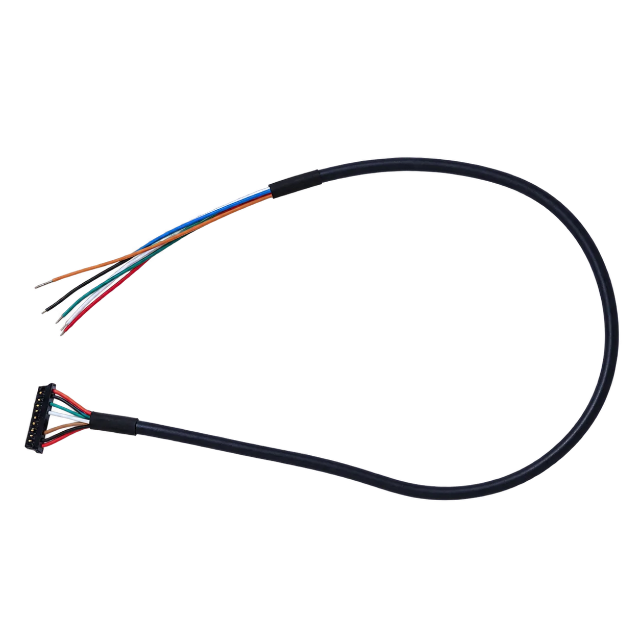
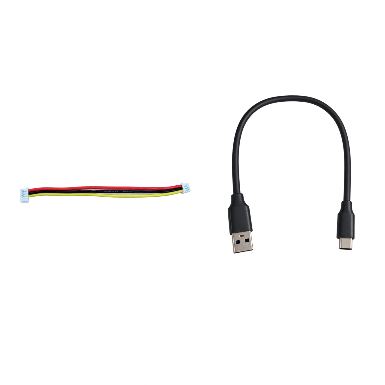
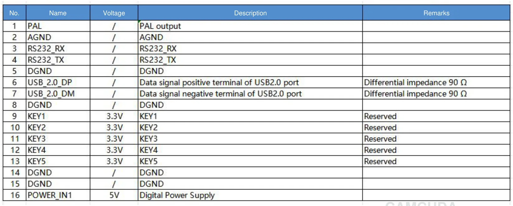
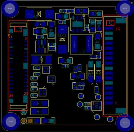
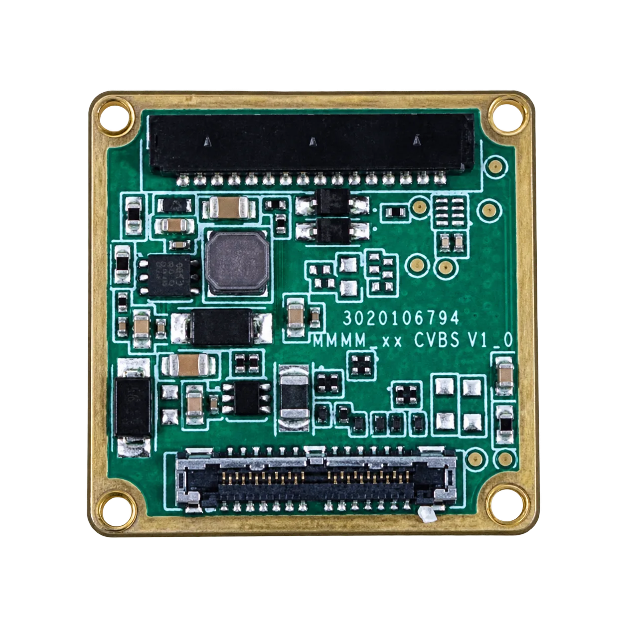
Use the matched pin table: Read this schematic with the original 16-pin signal table and board layout. Pin 16 is POWER_IN1, a 5 V input. The 26-pin MIPI/DVP schematic and complete table on PDF page 4 identify POWER_IN2 at pins 12, 25 and 26 as 5 V inputs. Do not apply 12 V to these inputs. Neither guide applies to the Type-C tailboard or SuperMini’s 30-pin bare-core connector; obtain the matched Type-C wiring guide before connecting its power or serial signals.
2. Thermal Dissipation and Heat Path Design
SuperMini lists ≤0.5 W typical core power excluding its expansion board; AeroMini lists <0.5 W typical module power at 25°C, with complete-kit power to be confirmed. Plan heat paths for the selected core and all added electronics. Uneven thermal conduction across the camera chassis creates internal temperature gradients that trigger excessive shutter calibrations, causing periodic video freezes. Make sure the camera module mounts to an aluminum or magnesium structure using high-performance thermal interface material (TIM) with a thermal conductivity rating of at least 3.0 W/m·K.
3. Vibration Isolation and Structural Rigidity
High-RPM drone propellers and motors generate mechanical vibrations, typically concentrated between 100 Hz and 800 Hz. High-frequency structural vibrations can induce mechanical microphonic noise across the suspended microbolometer membranes, degrading visual sharpness. Mount the core assembly on tuned elastomeric or silicone isolation dampers, and secure fine-pitch board-to-board connectors (such as the Hirose DF40C 30-pin interface) with structural locking brackets or strain-relieved cabling.
Comprehensive Engineering FAQ
Can you install an aftermarket thermal camera core onto consumer DJI drones like the Mini 4 Pro or Mavic 3 Classic?
What are the primary operational tradeoffs between turnkey DJI thermal drones and custom OEM thermal payloads?
How do frame rates differ between imaging-only cores (50 Hz) and thermographic measurement cores (30 Hz)?
📚 References & Further Reading
- Industry Standard: Wikipedia – Edge Computing Architectures
- Industry Standard: Bosch Security Systems – Industrial Monitoring Solutions
- Related Guide: CAMCUDA Core Selection: Interface, Resolution & Integration Checklist
- Related Guide: CAMCUDA Thermal Camera Suppliers: OEM RFQ Checklist
- Related Guide: CAMCUDA CVBS Thermal Camera Module Analog Video Integration