How Heat Sensing Cameras Work: OEM Engineering Guide to LWIR & Radiometry
How Heat Sensing Cameras Work: OEM Engineering Guide to LWIR & Radiometry
Thermal imaging has come a long way from the days of cryo-cooled, benchtop laboratory instruments that demanded half a rack of support electronics. Today, we are putting complete long-wave infrared (LWIR) camera engines into payloads that weigh less than a standard house key. But if you are an optical engineer, a UAV payload architect, or an instrumentation designer building systems for harsh industrial floors, you know that slapping a heat sensing camera core onto a PCB is never a simple plug-and-play job. You are dealing with uncooled microbolometers, delicate quantum-level resistance shifts, low-noise power routing, and tight optical tolerances where a fraction of a millikelvin can throw off your entire data pipeline.
Here’s the deal: capturing raw photons in the 8 to 14 micrometer window means managing severe physical trade-offs. You are balancing Noise Equivalent Temperature Difference (NETD) against thermal time constants, fighting off 1/f flicker noise, laying out squeaky-clean power rails with high power-supply rejection ratios, and matching optical aperture mechanics to tiny 8 µm or 12 µm pixel pitches. If your housing design traps heat unevenly, your focal plane array drifts, your factory non-uniformity correction collapses, and your thermal signatures become noisy junk.
Choosing the right thermal engine comes down to fundamental architectural decisions. Do you need qualitative edge-sharpened imaging for pilot situational awareness, or absolute, per-pixel radiometric temperature measurement? Are you dealing with dynamic detail enhancement (DDE) engines that blow out measurement linearity, or do you need calibrated 14-bit digital numbers for real-time telemetry? Whether you are certifying an aerial platform under FAA Unmanned Aircraft Systems airworthiness directives or deploying automated thermography arrays for round-the-clock predictive maintenance, you have to understand how microscopic resistance changes in a Vanadium Oxide (VOx) matrix translate into actionable thermal intelligence.
Table of Contents
- 👉 1. The Physics of LWIR: Planck’s Law, Emissivity, and Atmospheric Transmission
- 👉 2. Microbolometer Architecture: VOx vs. a-Si & ROIC Signal Processing
- 👉 3. Radiometry vs. Imaging-Only: Calibration, NUC, and Thermography Math
- 👉 4. Optical Considerations: Germanium Lens Design, F-Number, and SWaP-C Constraints
- 👉 5. Hardware Interfaces & Low-SWaP Electrical Integration
- 👉 6. OEM Product Selection: CAMCUDA Ultra-Light LWIR Thermal Camera Modules
- 👉 7. Deep-Dive OEM Integration FAQ
1. The Physics of LWIR: Planck’s Law, Emissivity, and Atmospheric Transmission
Everything in the universe sitting above absolute zero (0 Kelvin or -273.15 °C) throws off electromagnetic radiation. That radiation is the direct macroscopic result of thermal agitation: charged particles, atoms, and molecules vibrating and colliding at microscopic scales. To quantify this emitted photon flux, we start with Planck’s Radiation Law. Planck defines the spectral radiance emitted by an idealized blackbody as a direct mathematical function of absolute temperature and wavelength:
Mλ(λ, T) = (2π h c²) / [ λ⁵ · (exp(hc / (λ kB T)) – 1) ] [W · m⁻² · µm⁻¹]
In this equation, h is Planck’s constant (6.626 × 10⁻³⁴ J·s), c is the speed of light in vacuum (2.998 × 10⁸ m/s), kB is the Boltzmann constant (1.381 × 10⁻²³ J/K), λ is the electromagnetic wavelength in meters, and T is the target surface temperature in Kelvin. Integrating Planck’s distribution across all possible emission wavelengths brings us to the Stefan-Boltzmann Law. That law proves that total radiant exitance climbs with the fourth power of absolute temperature (j* = σT⁴, where σ ≈ 5.670 × 10⁻⁸ W·m⁻²·K⁻⁴). What does that mean on the test bench? Even minor increases in target temperature generate massive non-linear spikes in emitted infrared photon flux.
When you differentiate Planck’s equation with respect to wavelength, you get Wien’s Displacement Law (λmax = b / T, where b ≈ 2897.8 µm·K). For common terrestrial targets where surface temperatures sit right around 300 Kelvin (about 27 °C or 80 °F), peak spectral emission calculates cleanly:
λmax = 2897.8 µm·K / 300 K ≈ 9.66 µm
Look at where that peak lands: right in the middle of the Long-Wave Infrared (LWIR) atmospheric transmission window (8 µm to 14 µm). Atmospheric gases, especially water vapor (H₂O), carbon dioxide (CO₂), and ozone (O₃), create severe absorption notches across the broader infrared spectrum. While Mid-Wave Infrared (MWIR, 3–5 µm) works well for high-temperature turbine exhausts or specialized optical gas imaging, it demands complex, heavy, and power-hungry Stirling cryocoolers to suppress detector dark current. LWIR, on the other hand, punches through high ambient humidity, light maritime haze, and particulate smoke while operating with uncooled thermal detectors. That makes LWIR the indisputable choice for low-SWaP (Size, Weight, Power) integration.
Out in the field, real surfaces rarely behave like textbook blackbodies. An opaque solid target balances energy across spectral emissivity (ε), reflectivity (ρ), and transmissivity (τ):
ε(λ) + ρ(λ) + τ(λ) = 1 → For opaque targets (τ = 0): ε + ρ = 1
When setting up a heat sensing camera for industrial thermography, low-emissivity materials are your biggest trap. Polished aluminum, brass, or stainless steel can exhibit emissivity values below 0.10. That means over 90% of the energy hitting your camera core isn’t thermal emission from the object at all; it is ambient thermal clutter reflecting off the surface like a thermal mirror. To get accurate, repeatable temperature calculations, high-grade radiometric engines run inversion pipelines that dynamically subtract reflected background radiance using target emissivity, atmospheric distance, ambient temperature, and relative humidity coefficients.
2. Microbolometer Architecture: VOx vs. a-Si & ROIC Signal Processing
At the center of any modern uncooled LWIR thermal module is the Focal Plane Array (FPA) microbolometer. Unlike cooled quantum photodetectors that convert incoming photons straight into electron-hole pairs across a bandgap, an uncooled microbolometer is essentially an array of microscopic, thermally isolated resistor bridges suspended above a silicon readout substrate.
Each pixel features an infrared absorber membrane (typically silicon nitride, Si₃N₄) coupled directly to a thin-film thermistor material. Incoming 8–14 µm photons strike the membrane, heating the suspended bridge structure and shifting the thin-film layer’s electrical resistance. We measure the responsive efficiency of that thin film by its Temperature Coefficient of Resistance (TCR):
TCR (β) = (1 / R) · (dR / dT) [% / K]
| Engineering Parameter | Vanadium Oxide (VOx) | Amorphous Silicon (a-Si) |
|---|---|---|
| Typical TCR at 25 °C | -2.0% to -3.0% / K | -2.5% to -3.5% / K |
| 1/f Flicker Noise Floor | Significantly lower 1/f noise | Higher 1/f flicker noise |
| Thermal Sensitivity (NETD) | ≤ 30 mK to 40 mK | ≥ 50 mK to 80 mK |
| Pixel Pitch Scalability | Down to 8 µm and 12 µm | Primarily 17 µm (12 µm with higher noise) |
| Long-Term Stability | Exceptional structural stability | Susceptible to thermal aging drift |
In aerospace, defense, and high-reliability industrial automation, Vanadium Oxide (VOx) is the undisputed industry standard—championed across high-end platforms by optical engineering leaders like Opgal. While amorphous Silicon (a-Si) is cheaper to manufacture using standard CMOS lines, its higher 1/f flicker noise ruins its signal-to-noise ratio when you shrink pixel pitches down to 12 µm or 8 µm. VOx maintains a remarkably quiet electrical noise floor, allowing sensor designers to achieve NETD sensitivity ratings of ≤ 40 mK or better even on sub-10 µm architectures.
Directly beneath that micro-machined array sits the Readout Integrated Circuit (ROIC). During each frame capture cycle, the system executes a tightly timed sequence:
- ⚙️ Pulsed Voltage Bias: The ROIC applies short bias pulses across individual pixel lines to sample instantaneous resistance without causing self-heating on the micro-bridge.
- ⚙️ Current Integration: Micro-currents flow into per-column Capacitive Transimpedance Amplifiers (CTIA), integrating the signal over a defined exposure window.
- ⚙️ Correlated Double Sampling (CDS): The readout circuit takes two samples per frame to cancel out kTC reset noise and low-frequency baseline shifts.
- ⚙️ High-Resolution Digitization: On-chip Analog-to-Digital Converters (ADCs) convert the analog signals into raw 14-bit or 16-bit digital streams.
- ⚙️ DSP/FPGA Corrections: The digital core runs real-time Non-Uniformity Correction (NUC), Bad Pixel Replacement (BPR), and baseline drift compensation before streaming raw data to the host.
3. Radiometry vs. Imaging-Only: Calibration, NUC, and Thermography Math
One of the most expensive mistakes an OEM engineer can make is confusing an imaging-only thermal core with a fully calibrated radiometric thermal engine. They both use focal plane arrays sensitive to LWIR, but their onboard firmware, processing engines, and factory calibration routines are built for entirely different jobs.
An imaging-only thermal core is built strictly for qualitative contrast: spotting a lost hiker, navigating a drone at night, or tracking a vehicle. Its onboard DSP applies heavy spatial filtering, Dynamic Detail Enhancement (DDE), dynamic range compression, and aggressive Automatic Gain Control (AGC). It dynamically stretches contrast to make edges pop for human eyes. In doing so, it destroys the linear relationship between scene temperature and digital pixel output, making absolute temperature measurement mathematically impossible. If you want a complete breakdown of resolution and core options, check out our high-resolution thermal imaging camera OEM selection guide.
| System Attribute | Imaging-Only Thermal Cores | Radiometric (Thermographic) Cores |
|---|---|---|
| Primary Objective | Target detection, situational awareness, FPV | Precise per-pixel absolute temperature calculation |
| Image Processing | DDE, dynamic histogram equalization, AGC | Linear radiance conversion, Planck inversion math |
| Factory Calibration | Relative NUC offset and 2-point gain tables | Multi-temperature blackbody calibration curves |
| Output Data Stream | 8-bit YUV, BT.656, standard UVC video | 14-bit/16-bit RAW radiometric digital arrays (CDS3) |
| Environmental Inputs | None (fixed automated AGC response) | Target emissivity, ambient temp, distance, humidity |
In a true radiometric engine, the total infrared radiance striking the detector array (Ltot) breaks down into three distinct terms:
Ltot = ε · τatm · Lobj(Tobj) + (1 – ε) · τatm · Lamb(Tamb) + (1 – τatm) · Latm(Tatm)
Here, ε represents the target surface emissivity, τatm is the transmission factor of the intervening atmosphere, Lobj is the direct self-emission radiance of the target, Lamb is the ambient thermal radiance reflecting off the target, and Latm is the thermal emission of the air path between the target and lens.
The radiometric DSP isolates target radiance Lobj by subtracting atmospheric path emission and ambient reflections. It then computes the true absolute surface temperature Tobj using an inverted, factory-fitted Planck formulation:
Tobj = B / [ ln( R / (DNcorr – O) + F ) ] [Kelvin]
Where DNcorr is the non-uniformity corrected digital number delivered by the ROIC ADC, and R, B, F, O are precision calibration coefficients generated across multi-point blackbody chambers during manufacturing and stored in the core’s non-volatile flash. This calculation executes across hundreds of thousands of pixels every single frame at 30 to 60 Hz.
4. Optical Considerations: Germanium Lens Design, F-Number, and SWaP-C Constraints
Standard optical glasses like N-BK7, fused silica, or standard crown glass are completely opaque to LWIR photons; they absorb almost 100% of energy between 8 µm and 14 µm. That means thermal optical assemblies require specialized infrared materials. Monocrystalline Germanium (Ge) is the workhorse of the industry because of its massive refractive index (n ≈ 4.002 at 10 µm) and low optical dispersion. But Germanium comes with a major catch: an aggressive thermal coefficient of refractive index (dn/dT ≈ 3.96 × 10⁻⁴ / °C). If ambient temperatures swing during flight or outdoor industrial operations, an uncompensated Germanium lens quickly goes out of focus. Modern high-reliability systems solve this by combining Germanium with Chalcogenide glass elements (such as GASIR or BD6) inside passively athermalized mechanical barrels.
When selecting optics for an OEM heat sensing camera, you have to balance three critical optical parameters: focal length (f), Instantaneous Field of View (IFOV), and optical aperture speed (F-number).
The Instantaneous Field of View represents the exact spatial angle seen by an individual microbolometer pixel:
IFOV = p / f [radians] → IFOV (mrad) = [ p (µm) / f (mm) ]
Where p is the pixel pitch of the microbolometer (such as 8 µm or 12 µm) and f is the lens focal length. When you drop from a 12 µm pixel pitch to an ultra-dense 8 µm pitch, you can use a significantly shorter, lighter focal length lens while matching the exact spatial resolution and target recognition range of a larger, heavier setup. That optical weight reduction is a massive win for balancing UAV micro-gimbals.
Optical aperture speed is defined by the system F-number (F/# = f / D, where D is the entrance pupil diameter). Thermal irradiance (Efpa) hitting the focal plane array scales inversely with the square of the F-number:
Efpa ∝ 1 / (F/#)²
Look at what happens when you step down from an F/1.0 lens to an F/1.4 lens: you slash the photon flux reaching your detector by roughly 50% ((1.0 / 1.4)² ≈ 0.51). That cuts your effective thermal sensitivity (NETD) in half, turning a crisp 35 mK camera into a noisy 70 mK system. Unless weight or cost forces your hand, always design around fast, high-transmission F/1.0 athermalized optical assemblies.
5. Hardware Interfaces & Low-SWaP Electrical Integration
Getting clean performance out of an uncooled microbolometer module inside a tight UAV pod or industrial inspection housing requires obsessive attention to electrical isolation, grounding, and thermal dissipation. Microbolometer readouts measure micro-current shifts; poor board design will inject ripple straight into your imagery.
| Electrical Subsystem | Nominal Voltage Window | Noise & Integration Constraints |
|---|---|---|
| Main Power Rail (MAIN_POWER) | 3.8 V to 5.2 V (Typ 5.0 V) | < 10 mV peak-to-peak maximum noise; dedicated linear regulation recommended |
| Digital I/O & Interface Rail | 3.28 V to 3.32 V (Typ 3.3 V) | < 10 mV peak-to-peak; power sequencing must match core DSP boot timings |
| Core Digital Logic Rail | 1.78 V to 1.82 V (Typ 1.8 V) | < 1 mV RMS (1 Hz to 50 kHz); strictly isolated from external switching noise |
| Digital Video Interfaces | 2-Lane MIPI-CSI2 / 8-bit BT.656 | High-speed differential routing; requires 100 Ω controlled impedance |
| Serial Command & Control | UART (1.8 V Logic) / RS-232 | Direct CLI command parsing for palette, NUC shutter, and temperature queries |
High-frequency DC-DC switching noise on the power rails will show up as diagonal or horizontal striping across your thermal video. Always place dedicated low-noise Low-Dropout Regulators (LDOs) with a Power Supply Rejection Ratio (PSRR) over 75 dB at 100 kHz right at the camera header. For embedded edge compute boards (such as NVIDIA Jetson Orin, Rockchip RK3588, or Raspberry Pi CM4), routing via 2-lane MIPI-CSI2 gives you direct DMA access to 14-bit raw radiometric frames with sub-5 ms latency. For multi-spectral fusion designs, you can check out the dual-sensor architecture engineered into the URA-Z series dual-light fusion handheld thermal observer.
Thermal sinking on your carrier board is just as crucial. While an uncooled VOx module consumes under 0.5 W during continuous operation, heat generated by your main application processor, motor drivers, or power stages must never create uneven thermal gradients across the camera housing. Asymmetric heating causes localized drift across the microbolometer matrix, throwing off calibration and causing severe vignetting. Always bond the thermal core mounting block to your outer aluminum payload shell using high-performance thermal gap pads (k > 3.0 W/m·K).
6. OEM Product Selection: CAMCUDA Ultra-Light LWIR Thermal Camera Modules
Matching the right thermal module to your engineering constraints means balancing resolution, pixel pitch, interface support, weight budget, and radiometric requirements. Below is a detailed technical comparison of two proven OEM cores: the ultra-compact CAMCUDA SuperMini 640 / 640T and the high-framerate CAMCUDA AeroMini 640.
CAMCUDA SuperMini 640 / 640T Ultra-Light LWIR Thermal Camera Module
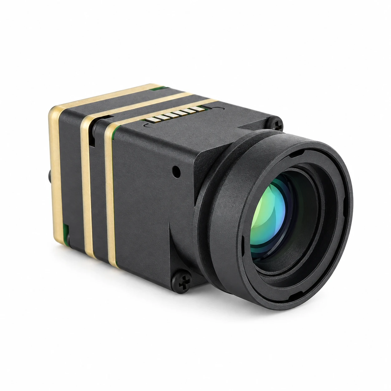
The CAMCUDA SuperMini 640 / 640T is built specifically for extreme Low-SWaP airborne and handheld integration. Packing a full 640 × 512 uncooled VOx focal plane array onto a breakthrough 8 µm pixel pitch, the bare module weighs under 3.5 grams with a microscopic 13 × 13 × 13.4 mm core envelope. Drawing less than 0.5 W under normal operation, this core is ideal for micro-UAV gimbals, tactical FPV airframes, and ultra-compact predictive maintenance instruments.
The SuperMini family comes in two specialized factory builds:
- ✅ CAMCUDA SuperMini 640 (Imaging Only): Runs at a fluid 50 Hz frame rate, streaming low-latency video over 8-bit LVCMOS (BT.656) or 2-lane MIPI. Perfect for high-speed drone piloting, FPV flight, and tactical reconnaissance.
- ✅ CAMCUDA SuperMini 640T (Radiometric): Runs at 30 Hz, delivering fully calibrated radiometric arrays over CDS3 and MIPI across dual operating temperature bands (-20 °C to +150 °C and +100 °C to +650 °C).
| Technical Parameter | Factory Specification (SuperMini 640 / 640T) |
|---|---|
| Detector Format | Uncooled Vanadium Oxide (VOx) Focal Plane Array |
| Array Resolution | 640 × 512 pixels |
| Pixel Pitch | 8 µm |
| Spectral Band | 8 µm to 14 µm (Long-Wave Infrared) |
| Thermal Sensitivity (NETD) | ≤ 40 mK @ 25 °C, F/1.0 |
| Frame Rate | SuperMini 640: 50 Hz | SuperMini 640T: 30 Hz |
| Core Dimensions & Weight | 13 × 13 × 13.4 mm | < 3.5 g (bare core without lens/flange) |
| Electrical Power Consumption | ≤ 0.5 W typical @ 25 °C |
| Hardware Interface Header | Hirose DF40C-30DP-0.4V(51) 30-Pin Connector |
| Digital Video Modes | 8-bit LVCMOS (BT656 on 640) / 2-Lane MIPI (CDS3 on 640T) |
| Command & Control | UART (1.8 V logic level) |
| Athermal Lens Options (F1.0) |
3.7 mm (90.0° × 68.2°, 2.16 mrad) 6.1 mm (46.6° × 37.6°, 1.31 mrad) 8.7 mm (40.0° × 32.2°, 0.92 mrad) 11.0 mm (24.9° × 20.0°, 0.73 mrad) |
CAMCUDA AeroMini 640×512 Uncooled LWIR USB Thermal Camera Core
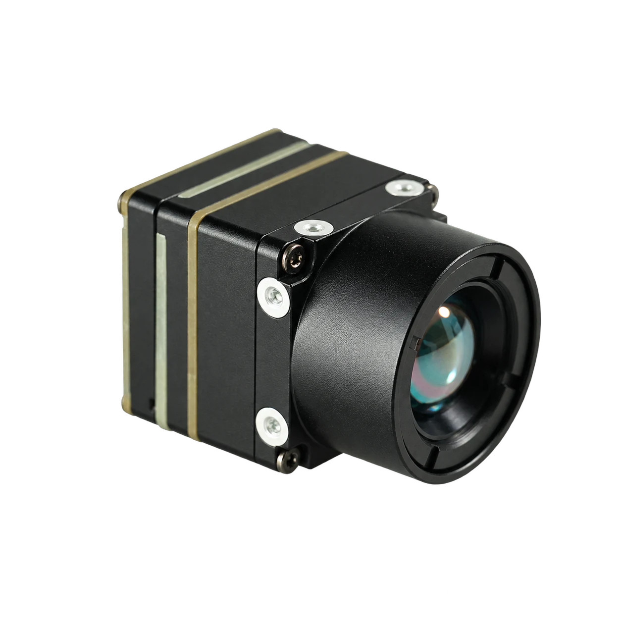
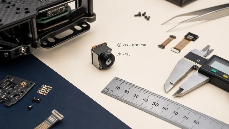
The CAMCUDA AeroMini 640 is an industrial LWIR engine engineered for multi-protocol integration across commercial UAVs, DJI-class payloads, and fixed industrial vision systems. Using a 640 × 512 VOx detector with a 12 µm pixel pitch, the module provides native factory options for 60 Hz or 30 Hz imaging along with an optional 25 Hz radiometric build. Weighing less than 20 grams in a rugged 21 × 21 × 28 mm housing, it delivers versatile connectivity options right out of the box.
| Technical Parameter | Factory Specification (AeroMini 640) |
|---|---|
| Detector Format | Uncooled Vanadium Oxide (VOx) |
| Array Resolution | 640 × 512 pixels |
| Pixel Pitch | 12 µm |
| Spectral Band | 8 µm to 14 µm (LWIR) |
| Thermal Sensitivity (NETD) | ≤ 50 mK @ 25 °C, F/1.0 (Optional ≤ 40 mK build available) |
| Native Frame Rates | 60 Hz default / 30 Hz option (Non-radiometric) | 25 Hz (Radiometric version) |
| Core Dimensions & Weight | 21 × 21 × 28 mm | < 20 g (without lens and mounting flange) |
| Power Consumption | < 0.5 W typical module consumption @ 25 °C |
| Digital Video Interfaces | YUV, USB 2.0 (UVC), BT.656 (dependent on interface board) |
| Analog Video Output | CVBS, PAL, NTSC (board dependent) |
| Serial Interfaces | UART, RS232, RS422 |
| Measurement Range (Radiometric) | -20 °C to +550 °C (Radiometric version with 9/13/18 mm optics) |
| Operating / Storage Temp | Operating: -40 °C to +80 °C | Storage: -50 °C to +85 °C |
| Optical Lens Lineup (F1.0) |
4 mm (100° × 82°) | 7 mm (64° × 52°) | 9 mm (48.7° × 38.6°) 13 mm (31.9° × 25.7°) | 15 mm (29.3° × 23.5°) | 18 mm (24.2° × 19.5°) 25 mm (17.5° × 14°) | 35 mm (12.5° × 10°) | 50 mm (8.8° × 7.0°) |
For more hardware pinouts, SDK sample code, and mechanical CAD models, visit the CAMCUDA Engineering Blog.

7. Deep-Dive OEM Integration FAQ
How does a heat sensing camera measure temperature remotely without physical contact?
Why do consumer-grade thermal cameras fall short for commercial UAV and industrial OEM designs?
Does every heat sensing camera automatically provide calibrated temperature data?
What mechanical and thermal considerations prevent calibration drift in sealed payloads?
📚 References & Further Reading
- Industry Standard: FAA Unmanned Aircraft Systems
- Industry Standard: Opgal
- Related Guide: CAMCUDA High-Resolution Thermal Camera OEM Selection Guide
- Related Guide: CAMCUDA URA-Z Dual-Light Fusion Thermal Observer
- Technical Knowledge Base: CAMCUDA Thermal Vision Engineering Blog