Thermal Camera Core: 11 Proven Checks for Reliable OEM RFQ
thermal camera core decisions become safer when the buyer connects product parameters to the real application: drone payload, outdoor observation, OEM embedded device, or industrial inspection. This guide uses CAMCUDA product context and practical RFQ questions so the thermal camera core choice is easier to validate.
thermal camera core: quick answer for reliable module selection
Start with CAMCUDA AeroMini 640 for a configurable UAV thermal camera core, then compare SuperMini 640 when core size and weight are tighter constraints. Match the imaging version, lens, interface board and complete assembly to your host before requesting a quotation. Neither imaging-only model measures temperature.
thermal camera core selection chart
A thermal camera core should be selected by detector, interface, power, dimensions, environment, and support documents.
| Core decision | What to check | Why it matters |
|---|---|---|
| Detector | Resolution, NETD, frame rate | Controls image usefulness. |
| Electrical | Video and control interface | Controls host development. |
| Mechanical | Weight and dimensions | Controls enclosure fit. |
| Environment | Temperature, humidity, vibration, shock | Controls field reliability. |
AeroMini and SuperMini thermal camera core parameters
| Selection check | AeroMini 640 imaging | SuperMini 640 imaging | What to confirm |
|---|---|---|---|
| Detector | Uncooled VOx | Uncooled VOx | Both are LWIR integration cores; select the complete assembly. |
| Resolution | 640 × 512 | 640 × 512 | Compare lens field of view and the intended target distance. |
| Imaging frame rate | 60 Hz factory default; 30 Hz factory option | 50 Hz | Imaging-only versions. Validate end-to-end latency on your host. |
| Pixel pitch | 12 μm | 8 μm | Use each model’s lens/FOV data; the same focal length is not a like-for-like comparison. |
| Spectral range | 8–14 μm | 8–14 μm | Check the enclosure window material for LWIR transmission. |
| NETD | ≤30 mK at 25°C, F/1.0 | ≤40 mK at 25°C, F1.0 | Published test conditions matter; bench-test the target scene. |
| Power input | 5 V or 12 V, board-dependent; POWER_IN1 / POWER_IN2 are 5 V inputs | MAIN_POWER: 3.8–5.2 V; separate 3.3 V and 1.8 V rails | Do not connect AeroMini’s illustrated 5 V pins to 12 V. Confirm the selected board, all rails and power-on timing. |
| Typical power at 25°C | <0.5 W module consumption; complete-kit consumption may differ | ≤0.5 W core consumption, excluding expansion board | Add the interface board, host and transmission hardware to the system power budget. |
| Digital video | YUV, USB and BT.656, board/firmware-dependent | 8-bit LVCMOS / BT656 and 2-lane MIPI | Confirm the exact output and host support. SuperMini BT656 and MIPI cannot operate simultaneously. |
| Control | UART, RS232 or RS422, depending on interface board | UART with 1.8 V logic | Confirm command protocol, logic levels, connector and cable. |
| Published weight | <20 g, excluding lens and flange | <3.5 g, excluding lens, flange and user expansion board | These are different measurement scopes, not ready-to-fly payload weights. |
| Published dimensions | 21 × 21 × 28 mm, excluding lens and flange | 13 × 13 × 13.4 mm, excluding lens, flange and user expansion board | Review the configured assembly drawing and cable clearance before enclosure design. |
| Operating temperature | −40°C to +80°C | −40°C to +70°C for imaging | Confirm thermal management and application conditions for the chosen version. |
| Humidity | 5–95%, non-condensing | 5–95%, non-condensing | Plan enclosure sealing and condensation control. |
| Vibration / shock | Request configuration-specific evidence | Request configuration-specific evidence | Validate the mounted payload; do not carry over another model’s test ratings. |
Source and version check: see the current AeroMini 640 specifications and SuperMini 640 / 640T specifications. Temperature measurement requires a different version: AeroMini radiometric is 25 Hz and availability-enquiry only; SuperMini 640T is 30 Hz. Confirm the temperature-data path, lens and interface separately.
For mechanical review, the SuperMini bare-core drawing, PDF page 13 of the complete manual excludes the lens and expansion board. Confirm the complete lens-and-board assembly drawing for either product before freezing the enclosure.
OEM and drone thermal camera core cases
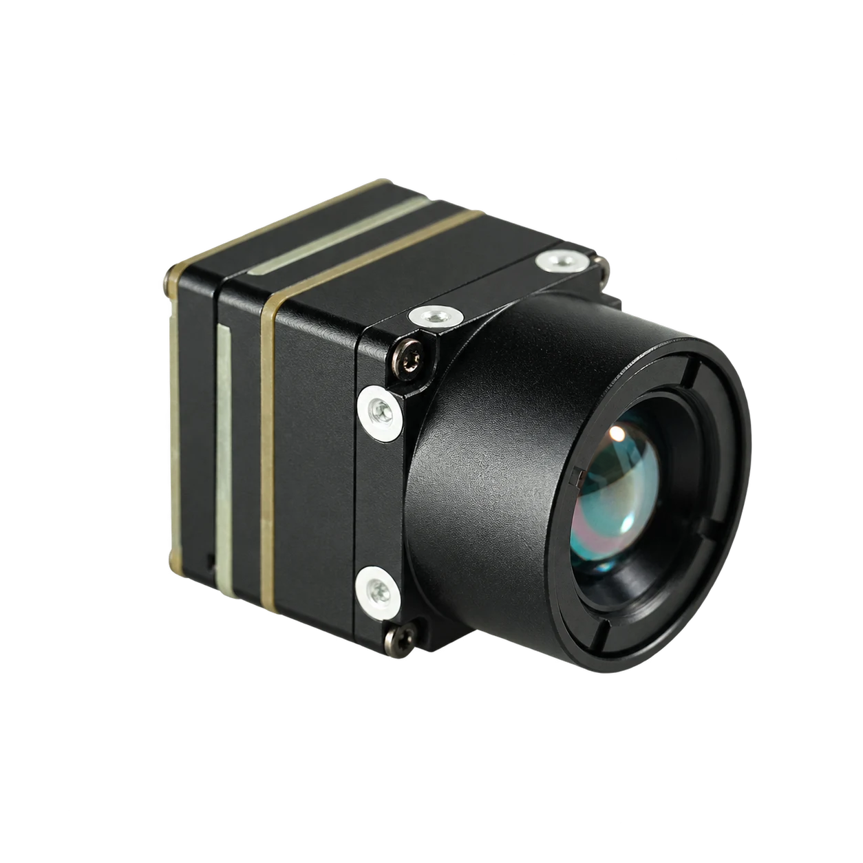
An OEM team should start its AeroMini 640 evaluation by choosing the interface board and proving video and control on the intended host. For a tighter core envelope, compare SuperMini 640’s 13 × 13 × 13.4 mm core against AeroMini’s 21 × 21 × 28 mm published dimensions, keeping their exclusions in view. A drone team must then budget the lens, boards, cables, mounting, enclosure and host electronics. Select the configuration after bench and mechanical checks; neither product listing proves drop-in compatibility with a particular aircraft.
USB and control interface table
| Interface topic | Current product paths | What to confirm |
|---|---|---|
| Video and board | AeroMini non-radiometric: USB + CVBS + MIPI or Type-C + CVBS board configurations. SuperMini: BT656 / MIPI at the 30-pin core interface; optional USB expansion board. | Confirm output availability, board revision, host OS, software and measured latency. SuperMini CVBS needs an external video-buffer IC. |
| Control | AeroMini: UART, RS232 or RS422, board-dependent. SuperMini: 1.8 V UART. | Verify the matching command guide and electrical levels; a serial label alone does not establish compatibility. |
| Power | AeroMini: board-specific input; illustrated POWER_IN1 / POWER_IN2 pins are 5 V. SuperMini: MAIN_POWER plus specified 3.3 V and 1.8 V rails. | Never feed 12 V into AeroMini’s illustrated 5 V pins. Check all SuperMini rail tolerances, noise limits and power-on timing. |
| Connector and wiring | Use the drawing for the selected board. AeroMini USB + CVBS + MIPI cable requires customer soldering; the Type-C package has a different connection guide. | Do not reuse a legacy module pinout. Confirm pin numbering, grounds, data pairs, cable clearance and exactly which boards and cables are included. |
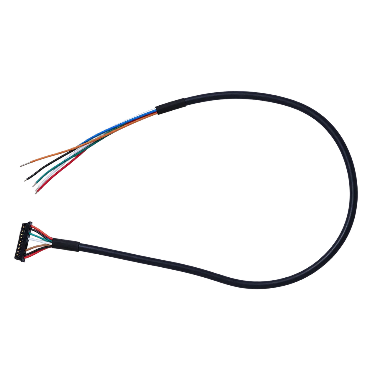

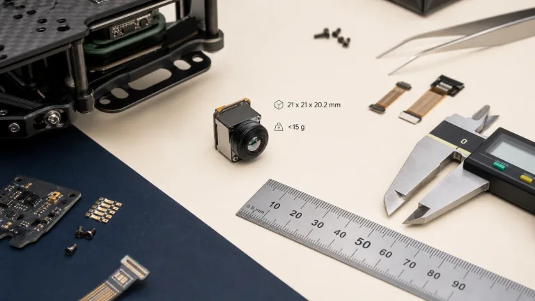
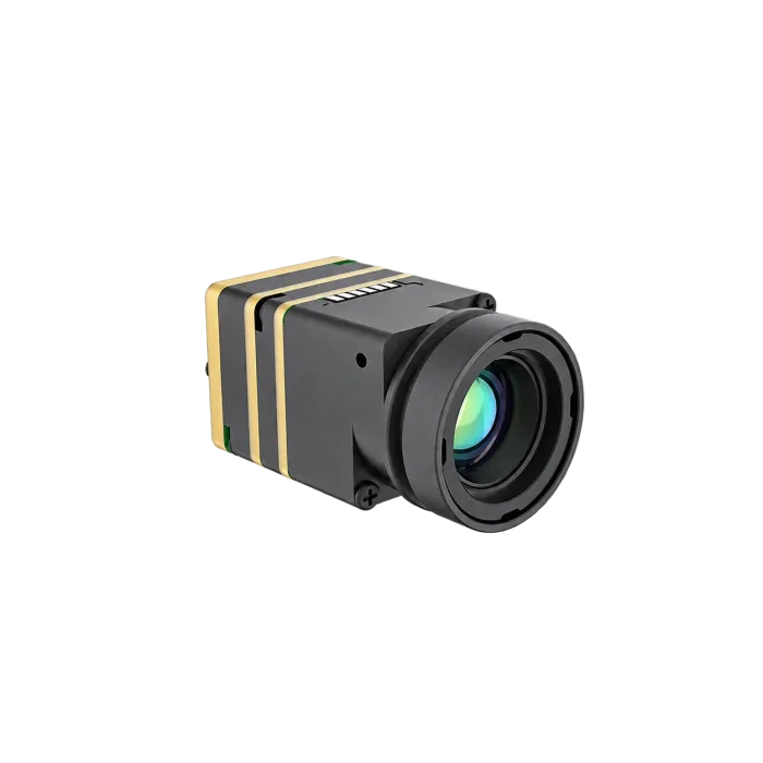
Check the matching 16-pin signal table and illustrated board layout together, then use the complete AeroMini datasheet for the other documented connector. SuperMini uses a separate 30-pin core interface in its complete manual, PDF pages 6–7; its product photograph below is an appearance reference.
For host-interface background, the MIPI Alliance CSI-2 overview explains camera-to-processor image transport. Use the selected module’s documentation to confirm its actual protocol, lane configuration and data format; the standard overview does not establish product or host compatibility.
Thermal camera core mistakes
- Confusing core, module, and finished camera.
- Ignoring host interface.
- Skipping mechanical drawing review.
- Not checking power and environment.
FAQ for thermal camera core buyers
What is a thermal camera core?
A core is an integration component used inside another thermal imaging system.
Is 640 × 512 always best?
No. It is useful for detail, but cost, lens, and host constraints matter.
Why does interface matter?
It affects host board, software, cable, and control path.
Does weight matter?
Yes for drones and compact devices.
What should I ask for?
Product detail, drawings, interface notes, and RFQ matching.
Can CAMCUDA help choose a core?
Yes, with application, host, lens, and quantity details.
Is it a finished camera?
No, not unless sold with enclosure/software as a finished device.
What is the biggest risk?
Buying before host and mechanical constraints are known.
thermal camera core validation workflow before purchase
A practical thermal camera core validation workflow should start with a written requirement sheet. The sheet should name the application, target distance, lens/FOV expectation, host processor, interface path, power rail, mechanical envelope, operating environment, quantity range, and destination market. This simple document makes the supplier conversation more useful than a generic request for price.
For engineering teams, the second step is a bench test plan. Confirm whether the thermal camera core can produce usable video on the intended host, whether the control path is documented, whether the module can be powered safely, and whether the image settings are enough for the target scene. For procurement teams, the same test plan becomes a checklist for comparing samples and supplier responses.
The third step is a field or application simulation. A drone payload should be checked against weight, vibration, flight height, and reporting workflow. An outdoor system should be checked against enclosure, condensation risk, lens window, mounting position, and day/night operation. An OEM embedded system should be checked against PCB layout, cable exit, software integration, and future production repeatability.
Example RFQ language for CAMCUDA
Instead of writing only “please quote a thermal camera core,” use a more complete request: “We are building a thermal imaging product for [application]. The host platform is [processor/system]. We need [interface] output, [lens/FOV] target, [quantity] units, and the destination market is [region]. Please recommend a module path, drawing/document package, sample availability, and integration risks.”
This RFQ style improves technical matching and helps CAMCUDA respond with a useful product path. It also protects the buyer from comparing incompatible modules just because they share a similar resolution or product photo.
How to compare suppliers for thermal camera core
When comparing suppliers, avoid a spreadsheet that only lists price and resolution. A stronger thermal camera core comparison should include whether the supplier can provide product detail pages, drawings, interface notes, realistic lead-time discussion, media assets, and application guidance. A supplier that can explain integration risk is usually easier to work with than one that only sends a short quote.
For CAMCUDA buyers in Europe and North America, documentation and communication also matter. Ask whether the supplier can confirm the product model, clarify the interface, explain what is included in the module scope, and identify which requirements need engineering review. If the answer is vague, the project may still be possible, but the buyer should treat the quotation as incomplete.
Acceptance test checklist after samples arrive
- Confirm the shipped model matches the quoted thermal camera core path.
- Check basic power-up behavior with the intended host or evaluation platform.
- Verify video output and control communication before mechanical integration.
- Compare image output under at least two realistic scenes.
- Review mechanical fit with cable, mount, enclosure, and lens/window constraints included.
- Record questions for the supplier before moving to production quantity.
This acceptance step is especially important for thermal imaging projects because many issues do not appear in a product photo. The thermal camera core may look correct but still require interface adjustment, lens matching, or enclosure changes. Treat the first sample as an engineering validation tool rather than a final production approval.