DJI Mavic Thermal: Radiometric Specs, UAV Limitations & Custom OEM Alternatives
DJI Mavic Thermal: Radiometric Specs, UAV Limitations & Custom OEM Alternatives
Aerial long-wave infrared (LWIR) imaging has shifted from a specialized defense capability to a day-in, day-out baseline across utility inspection, structural monitoring, public safety, and tactical reconnaissance. Off-the-shelf commercial platforms—specifically turnkey systems like the DJI Mavic 2 Enterprise Advanced and Mavic 3 Thermal (M3T)—deserve credit for making aerial thermography accessible. By packing an uncooled microbolometer alongside a visible sensor onto a sub-kilogram folding quadcopter, these turnkey drones let utility crews and emergency teams pull basic thermal scans right out of the case. But when you are building mission-critical platforms, autonomous infrastructure scanners, or defense-grade reconnaissance birds, compare the documented camera interfaces, SDK support, optics and aircraft limits with your system requirements.
For systems engineers, fixed optical fields of view, vendor-specific telemetry and supported development interfaces shape the integration options. If your design calls for real-time edge-AI processing, long-standoff utility inspection, custom micro-gimbals, or strict SWaP-C (Size, Weight, Power, and Cost) optimization, compare the exact aircraft, camera and SDK support with a custom payload architecture. When you’re running object detection or automated visual tracking on an NVIDIA Jetson Orin or custom FPGA pipeline, define the required image format, temperature data and measured end-to-end latency first. OEM paths such as 2-lane MIPI CSI-2, parallel LVCMOS/BT.656 or thermographic CDS3 can support a host pipeline, but availability and parsing depend on the selected model.
This engineering teardown breaks down the radiometric realities and hardware bottlenecks of turnkey Mavic thermal payloads, walks through the underlying sensor and optical physics (from IFOV to convective drift), and lays out the practical hardware architecture for building high-performance, low-SWaP custom payloads using modular OEM forward-looking infrared (FLIR / LWIR) cores.
Table of Contents
- 👉 1. Turnkey Thermal UAV Architecture: Radiometric Analysis of DJI Mavic Thermal Systems
- 👉 2. Mechanical, Protocol & Edge-AI Integration Ceilings in Closed Drone Systems
- 👉 3. Optical & Sensor Physics: NETD, IFOV & Radiometric Calibration Drift
- 👉 4. Modular Open-Architecture LWIR Cores vs. Closed UAV Systems
- 👉 5. Ultra-Low SWaP OEM LWIR Thermal Camera Modules: Engineering Deep-Dive
- 👉 6. Comprehensive Engineering Specifications Comparison
- 👉 7. Electrical, Thermal & Protocol Integration Guide for Custom UAV Payloads
- 👉 8. OEM Procurement, Optics Selection & RFQ Verification Blueprint
- 👉 9. Deep-Dive Engineering FAQ
1. Turnkey Thermal UAV Architecture: Radiometric Analysis of DJI Mavic Thermal Systems
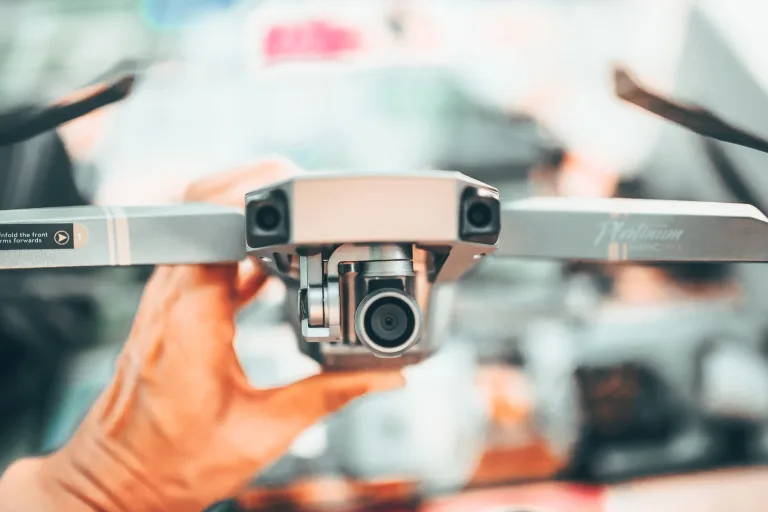
The popularity of the Mavic thermal line comes down to pure convenience. On aircraft like the DJI Mavic 3 Thermal, the factory packages an uncooled Vanadium Oxide (VOx) focal plane array, wide-angle and telephoto visible cameras onto a balanced 3-axis gimbal. For human-in-the-loop tasks—like a field technician checking a commercial flat roof for standing water or a firefighter looking for wildland hotspots from a tablet screen—it gets the job done without custom engineering.
Under the hood, these systems use an uncooled 640 × 512 VOx microbolometer with a 12 μm pixel pitch operating across the standard 8–14 μm long-wave infrared atmospheric window. Microbolometer pixels are prone to drift and spatial non-uniformity across the array, making the configured Non-Uniformity Correction (NUC) workflow important. Follow the model-specific NUC workflow and test image interruptions; a fixed correction interval and internal gain/offset procedure are not established by the cited DJI specification.
Look at how the radiometric data flows through one of these closed platforms:
- ⚙️ Analog-to-Digital Conversion: The detector signal is digitized inside the camera. DJI specifies 16-bit R-JPEG thermal still images for M3T; that exported file depth does not establish the internal ADC depth or a raw live-video interface.
- ⚙️ Internal Radiometric Engine: The camera processes detector data for imaging and temperature measurement. Use the supported radiometric files and documented processing tools; do not assume an unpublished LUT, thermistor layout or calibration-polynomial implementation.
- ⚙️ Compression & Encapsulation: DJI specifies H.264 video and O3 Enterprise transmission for M3T, while thermal stills are saved as 16-bit R-JPEG. Image exports, temperature analysis and supported live-video SDK access are separate workflows; verify the aircraft, camera and software combination rather than treating them as one proprietary temperature stream.
This integrated setup supports turnkey inspection. For low-latency autonomy, pixel-level computer vision or offline deployment, compare the documented exports, SDK access and operating requirements with the data path your system needs.
2. Mechanical, Protocol & Edge-AI Integration Ceilings in Closed Drone Systems
Once you move past manual piloting into automated sub-station inspections, edge-AI tracking, or sovereign defense platforms, evaluate these integration constraints for the selected turnkey commercial platform:
1. Mechanical and Gimbal Lock-in: Turnkey aerial gimbals are balanced, tuned, and counterweighted exclusively for the factory optical payload. Motor drive currents, PID loops, and inertia maps assume a fixed center of gravity. Changing a lens, filter or camera alters the optical calibration, mass, inertia and integration requirements; the cited documentation does not establish a supported swap procedure or inevitable motor damage. For reuse across unmanned ground vehicles (UGVs), mast systems or fixed perimeter sensors, assess a separately documented OEM module.
2. Video Latency & Edge-AI Degradation: Automated flight control, obstacle avoidance, and target tracking require image quality and latency suitable for the validated control or perception pipeline. M3T uses H.264 video and O3 Enterprise transmission; DJI lists approximately 200 ms transmission latency, dependent on environment and mobile device. This is not a guaranteed glass-to-glass figure for every integration. Lossy compression introduces macroblocking and smooths out subtle infrared temperature gradients. When feeding a Convolutional Neural Network (CNN), measure the effect of the actual compression, resolution and latency on your validation set.
3. Proprietary Protocols and Software Locks: A turnkey camera does not expose the same integration contract as a bare OEM core. DJI provides documented development interfaces for supported aircraft and camera combinations, so review the relevant SDK, firmware, live-video access and offline requirements. Neither unrestricted sensor-bus access nor mandatory cloud handshakes should be inferred without model-specific documentation.
4. Fixed Wide-Angle Optics: The M3T thermal specification lists a fixed lens with 61° diagonal FOV, not 61° horizontal FOV. A wide field can provide situational awareness close up while reducing the target pixels available when inspecting high-voltage substations or communications towers from a safe standoff distance. Staying clear of electromagnetic interference (EMI) or tower guy-wires means your target ends up covering only a handful of pixels on the sensor.
3. Optical & Sensor Physics: NETD, IFOV & Radiometric Calibration Drift
Building high-performance thermal payloads requires a solid grip on the optical physics governing resolution, detector sensitivity, and environmental drift, with general background available in industrial vision publications such as Vision Systems Design.
A nominal near-axis pixel angle can be estimated from the Instantaneous Field of View (IFOV), using detector pitch and lens focal length. Actual resolving capability also depends on optics, contrast and processing:
IFOV (mrad) = [ Pixel Pitch (p in μm) / Focal Length (f in mm) ]
For a near-axis, nadir view of a flat target plane at distance D, estimate the one-pixel Ground Sampling Distance (d). Oblique views, edge-of-frame distortion and three-dimensional targets need a separate projection model:
d (m) ≈ IFOV (mrad) × D (m) / 1000
In quantitative aerial thermography, detecting a target is not the same as measuring its temperature accurately. The Point Spread Function (PSF), focus, target contrast and calibrated measurement footprint matter. The table gives a nominal three-pixel footprint (three pixel widths across a target), not a detection, recognition or temperature-accuracy guarantee. Its horizontal FOV values belong to the listed SuperMini 8 μm optical configurations. The 12 μm columns are theoretical same-focal-length comparisons, not AeroMini lens options or a claim of identical FOV.
| Focal Length (f) | Horizontal FOV (SuperMini 8 μm optics) | IFOV (8 μm Detector) | IFOV (12 μm, theoretical same focal length) | Nominal 3-Pixel Footprint @ 50 m |
|---|---|---|---|---|
| 3.7 mm (F1.0) | 90.0° | 2.16 mrad | 3.24 mrad | 32.4 cm (8 μm) / 48.6 cm (12 μm) |
| 6.1 mm (F1.0) | 46.6° | 1.31 mrad | 1.97 mrad | 19.7 cm (8 μm) / 29.5 cm (12 μm) |
| 8.7 mm (F1.0) | 40.0° | 0.92 mrad | 1.38 mrad | 13.8 cm (8 μm) / 20.7 cm (12 μm) |
| 11.0 mm (F1.0) | 24.9° | 0.73 mrad | 1.09 mrad | 10.9 cm (8 μm) / 16.4 cm (12 μm) |
Notice the numbers in that matrix: moving from a standard 12 μm detector to a high-density 8 μm microbolometer drops your IFOV by 33% at the exact same focal length. At the same array resolution and field of view, a smaller pitch permits a shorter nominal focal length. Actual lens mass, resolving performance and aircraft endurance depend on the optical and complete-system design.
Thermal Sensitivity (NETD): Noise Equivalent Temperature Difference (NETD), measured in milliKelvins (mK), represents the smallest temperature delta the sensor can pull out of electrical background noise. An uncooled core rated at NETD ≤ 40 mK at 25°C with an F1.0 lens states a sensitivity under those test conditions. It does not establish absolute temperature accuracy or guarantee detection of a particular defect under flight airflow; validate the selected thermographic model, optics and inspection procedure.
Dynamic Flight Drift: In the field, drones deal with rapid altitude shifts, prop wash, and sudden ambient temperature drops during fast climbs. Convective airflow rushing across an exposed lens barrel creates internal thermal gradients, shifting radiometric calibration mid-flight. Use model-matched optics and the documented calibration workflow, then validate drift through representative airflow, ambient changes and warm-up. Athermal optics help maintain focus but do not by themselves establish radiometric accuracy; an internal thermistor array or polynomial implementation is not specified here.
4. Modular Open-Architecture LWIR Cores vs. Closed UAV Systems
To cut past the roadblocks of closed commercial platforms, UAV engineering teams and defense integrators build on modular, open-architecture LWIR camera cores. Integrating an uncooled OEM module directly into your mechanical airframe, micro-gimbal, or embedded AI compute carrier lets you select the host architecture, optics and supported data path, with responsibility for integration and qualification of the complete system.
Here is what an open OEM architecture delivers on the bench:
- ✅ Digital Video Interfaces: Model-specific 2-lane MIPI CSI-2 or 8-bit LVCMOS / BT.656 paths can avoid a wireless encoding stage. Integration into NVIDIA Jetson, Raspberry Pi or FPGA hardware still requires a compatible receiver, driver, data format and buffering design; measure complete-system latency rather than assuming zero-lag or sub-frame operation.
- ✅ Radiometric CDS3 Streaming: SuperMini 640T carries YUV422 image data plus temperature data over CDS3. Its MIPI RAW8 transport is reassembled by the host into 16-bit image and temperature values, low byte first. Match the actual output mode and conversion instructions before implementing temperature thresholds or isotherms; imaging-only SuperMini 640 and AeroMini imaging do not measure temperature.
- ✅ Factory-Matched Athermal Optics: Select the exact optical barrel your mission demands—whether that’s a wide 3.7 mm F1.0 lens for close-quarter indoor mapping or an 11.0 mm F1.0 telephoto lens for a narrower field; validate target footprint and the inspection distance for the actual task.
- ✅ Ultra-Low SWaP Footprint: With bare module dimensions down to 13 × 13 × 13.4 mm and weight under 3.5 grams, SuperMini provides a compact bare-core starting point; those dimensions and mass exclude the lens, flange and user expansion board. Budget the selected optics, electronics, cabling and gimbal separately.
For engineering teams working on custom aerial payloads, check out the architecture specs across our CAMCUDA Drone Camera Systems lineup.
5. Ultra-Low SWaP OEM LWIR Thermal Camera Modules: Engineering Deep-Dive
CAMCUDA manufactures ultra-compact, uncooled long-wave infrared camera cores purpose-built for OEM mechanical integration, micro-gimbals, and embedded drone payloads.
CAMCUDA SuperMini 640 / 640T Ultra-Light LWIR Thermal Camera Module
The CAMCUDA SuperMini 640 / 640T packs a 640 × 512 uncooled VOx microbolometer with an 8 μm pixel pitch into an ultra-compact 13 × 13 × 13.4 mm core weighing under 3.5 grams; both values exclude the lens, flange and user expansion board. Designed for tight gimbal enclosures, micro-reconnaissance drones, tactical FPV builds, and embedded edge compute boards, it delivers high thermal sensitivity (NETD ≤ 40 mK @ 25°C, F1.0) with typical core consumption ≤ 0.5 W at 25°C, excluding the expansion board.
The platform comes in two distinct hardware configurations:
- ⚙️ CAMCUDA SuperMini 640 (Imaging Only): Runs at a fast 50 Hz frame rate for low-latency FPV piloting and target tracking over 8-bit LVCMOS / BT656 and 2-lane MIPI buses.
- ⚙️ CAMCUDA SuperMini 640T (Thermographic): Operates at 30 Hz with fully calibrated per-pixel radiometric temperature output across dual ranges (−20°C to +150°C and 100°C to +650°C) via documented CDS3 and MIPI image-plus-temperature paths. Typical accuracy is ±2°C or ±2% of reading at −20°C to +60°C ambient; these thermography specifications do not apply to imaging-only SuperMini 640.
Athermal F1.0 Optical Configurations
| Focal Length | Field of View (H × V) | Aperture | IFOV |
|---|---|---|---|
| 3.7 mm | 90.0° × 68.2° | F1.0 | 2.16 mrad |
| 6.1 mm | 46.6° × 37.6° | F1.0 | 1.31 mrad |
| 8.7 mm | 40.0° × 32.2° | F1.0 | 0.92 mrad |
| 11.0 mm | 24.9° × 20.0° | F1.0 | 0.73 mrad |
Electrical & Interface Specifications
| Interface / Rail | Published Requirement | Integration Notes |
|---|---|---|
| Host Connector | Hirose DF40C-30DP-0.4V(51) 30-pin | High-density micro board-to-board header |
| MAIN_POWER | 3.8–5.2 V (Typical 5 V) | ≤ 10 mV p-p maximum allowable noise |
| +3.3 V Rail | 3.28–3.32 V | ≤ 10 mV p-p maximum allowable noise |
| +1.8 V Rail | 1.78–1.82 V | ≤ 1 mV RMS (1 Hz–50 kHz) |
| Digital Video Output | 8-bit LVCMOS / BT656; 2-lane MIPI | 640: BT656 · 640T: CDS3 image + temperature; MIPI and BT656 cannot operate simultaneously |
| Serial Control Bus | UART (1.8 V Logic) | TX/RX defined from core perspective |
| Evaluation Board | Optional TMS6102V100F022 Expansion | Optional 4-pin USB 2.0 board for either model; confirm host software and supplied items |
CAMCUDA AeroMini 640 Non-Radiometric 9 mm OEM Configuration
The CAMCUDA AeroMini 640 configuration here is non-radiometric, with a 9 mm F1.0 lens and the USB + CVBS + MIPI interface package. It uses a 640 × 512, 12 μm VOx detector for OEM imaging, with 60 Hz factory default or a 30 Hz factory option; it does not measure temperature. The selected package includes a USB cable requiring customer soldering. Standard RAW or minimally processed AeroMini output requires a customization assessment.
Keep the low-resolution, low-power route separate: projects needing 160-class sensing, a microcontroller SPI interface or substantially lower power need another configuration verified against those requirements. Neither AeroMini nor SuperMini 640 is an equivalent substitute for that low-resolution/SPI/power budget.
The separate AeroMini 25 Hz radiometric version has a published −20°C to +550°C reference range, but is currently out of stock and enquiry only: documented lenses are 9/13/18 mm, interface and measurement details require confirmation, and no online purchase or pre-order is available.
Technical Specifications Matrix
| Parameter | Specification Value |
|---|---|
| Detector Resolution | 640 × 512 (non-radiometric imaging) |
| Pixel Pitch & Spectral Band | 12 μm · 8–14 μm LWIR |
| Frame Rate | 60 Hz default / 30 Hz factory option |
| 9 mm Lens / Field of View (H × V) | F1.0 · 48.7° × 38.6° |
| Power Supply & Consumption | Illustrated POWER_IN1 / POWER_IN2: 5 V only; <0.5 W typical module power at 25°C, kit power may differ |
| Host Data Interface | Selected USB + CVBS + MIPI package; verify host format and enabled output combination |
| Physical Connection | Use matching 16-pin USB/CVBS and 26-pin MIPI/DVP references; these do not describe the separate Type-C board |
| Operating Temperature Range | −40°C to +80°C operating; not a temperature-measurement range |
6. Comprehensive Engineering Specifications Comparison
Here is a direct side-by-side comparison between turnkey commercial drone payloads and CAMCUDA open OEM long-wave infrared modules across electrical, optical, and interface metrics. The rows identify bare-core, configured-module and complete-aircraft values separately; they are not like-for-like payload mass or power measurements.
| Engineering Parameter | CAMCUDA SuperMini 640 / 640T | CAMCUDA AeroMini 640 (9 mm; non-radiometric) | DJI Mavic 3 Thermal (Turnkey) |
|---|---|---|---|
| Detector Format | Uncooled VOx microbolometer | Uncooled VOx microbolometer | Uncooled VOx microbolometer |
| Array Resolution | 640 × 512 | 640 × 512 | 640 × 512 |
| Pixel Pitch | 8 μm | 12 μm | 12 μm |
| Core Physical Footprint | 13 × 13 × 13.4 mm; excludes lens, flange and user expansion board | 21 × 21 × 28 mm; excludes lens and flange | Fixed integrated aircraft payload |
| Published Mass / Scope | <3.5 g; excludes lens, flange and user expansion board | <20 g; excludes lens and flange | 920 g complete aircraft, with propellers, without accessories; not a bare-core mass |
| Thermal Sensitivity (NETD) | ≤ 40 mK (@ 25°C, F1.0) | ≤30 mK at 25°C, F/1.0 | ≤50 mK at F1.0 |
| Output Frame Rate | 640: 50 Hz · 640T: 30 Hz | 60 Hz default / 30 Hz factory option | 30 Hz |
| Optical Flexibility | Factory-matched F1.0 options: 3.7 / 6.1 / 8.7 / 11 mm | Selected 9 mm F1.0: 48.7° H × 38.6° V; other lenses have their own FOV | Fixed thermal lens; 61° diagonal FOV |
| Host Interfaces | 2-lane MIPI; 640: LVCMOS/BT656, 640T: CDS3. Optional USB board; BT656/MIPI not simultaneous | Selected USB + CVBS + MIPI package; not SPI. Match board, firmware and host | O3 Enterprise live video; supported DJI SDK and image-file workflows |
| Power Consumption | ≤0.5 W typical core power at 25°C, excluding expansion board | <0.5 W typical module power at 25°C; complete-kit draw may differ | Aircraft powered by LiPo 4S battery; not a thermal-core power figure |
| Radiometric Measurement Range | −20°C to +150°C / 100°C to +650°C (640T) | None for this non-radiometric configuration; separate 25 Hz version requires availability enquiry | −20°C to +150°C (high gain) / 0°C to +500°C (low gain) |
| Edge-AI & Compute Pipeline | Receiver, driver, image/TEMP parsing and host performance require validation | Validate selected board output and host software; no MCU/SPI compatibility implied | Documented image exports and supported SDK live-video interfaces; validate exact platform |
7. Electrical, Thermal & Protocol Integration Guide for Custom UAV Payloads
When you sit down at the bench to integrate a micro-bolometer core like the CAMCUDA SuperMini 640 / 640T into a stabilized gimbal, three things make or break your build: clean power routing, high-speed differential signal integrity, and conductive heat dissipation.
1. Power Supply Conditioning: Microbolometers detect fractional changes in bridge resistance. Supply noise can affect image quality; validate every rail under startup, steady capture and changing motor loads rather than diagnosing an artifact from appearance alone.
- ⚙️ Dedicated Linear Regulators: SuperMini MAIN_POWER is 3.8–5.2 V, typically 5 V, with 10 mV peak-to-peak maximum noise. Select regulation and filtering to meet the measured rail limits and startup sequence; a particular LDO topology is not established as mandatory by the manual.
- ⚙️ Precision Core Rails: Provide +3.3 V at 3.28–3.32 V with 10 mV p-p maximum noise, and +1.8 V at 1.78–1.82 V with a 1 mV RMS noise limit over 1 Hz–50 kHz. These are separate bare-core rails, not a single 5 V input.
- ⚙️ ESC & Motor Isolation: Keep high-power brushless motor lines physically separate from the thermal sensor PCB. Evaluate filtering, return paths and cable routing against measured switching disturbances from the electronic speed controllers (ESCs); verify the camera rail limits with the motors operating.
2. High-Speed Digital Video Routing: The SuperMini uses a 30-pin Hirose DF40C-30DP-0.4V(51) high-density connector. Use the SuperMini Product Manual V1.0.0 for the complete pin table, power-on sequence and model-specific formats. SuperMini CVBS output requires an external video-buffer IC. AeroMini uses different boards: its illustrated POWER_IN1/POWER_IN2 pins are 5 V only, never 12 V. Match the 16-pin USB/CVBS and 26-pin MIPI/DVP references to the supplied board; they do not describe the separate Type-C board. Keep your board routing aligned with the selected interface:
- ⚙️ MIPI CSI-2 Differential Routing: SuperMini specifies two data lanes at 216 Mbps per lane and a 108 MHz clock lane. Apply the selected host receiver and PCB stackup requirements for impedance, length matching and signal integrity, then validate the assembled link on the intended host.
- ⚙️ Parallel LVCMOS / BT.656 Lines: When feeding an onboard FPGA, keep your parallel lines short and route over an unbroken, solid ground plane. The manual states that MIPI and BT.656 cannot operate at the same time; follow the mode-specific pin assignments in the 30-pin definition.
- ⚙️ Serial Control: Use the documented UART commands at 1.8 V logic, with TX/RX defined from the core perspective. Check host I/O voltage tolerance and use suitable level translation when required; UART control does not imply that the same microcontroller can receive the video stream.
3. Thermal Dissipation in Sealed Gimbals: The SuperMini reference is ≤0.5 W typical core power at 25°C, excluding the expansion board, within a 13 × 13 mm footprint. A sealed gimbal needs a thermal budget that includes optics, electronics and actual operating conditions:
- ⚙️ Chassis Heat-Sinking: Design and test a conductive heat path between the core and enclosure. Select pad material, thickness, compression and contact area through thermal and mechanical testing of the complete assembly.
- ⚙️ Avoid Hot Neighbors: Keep the thermal core away from high-power video transmitters (VTX) or flight controller power boards to prevent uneven thermal gradients across the sensor plane.
8. OEM Procurement, Optics Selection & RFQ Verification Blueprint
Before locking in tooling or issuing an RFQ for your thermal payload, run your team through this engineering checklist:
- ⚙️ Mission Profile: Confirm whether your mission requires high-frame-rate tracking and piloting (CAMCUDA SuperMini 640 @ 50 Hz) or calibrated per-pixel radiometric thermography (CAMCUDA SuperMini 640T @ 30 Hz with CDS3 data).
- ⚙️ Optics Selection: Calculate the nominal IFOV and three-pixel footprint using Section 3, then validate the actual detection or measurement requirement. Choose from 3.7 mm (90° HFOV wide angle) up to 11.0 mm (24.9° HFOV narrow angle) athermal F1.0 lenses.
- ⚙️ Host Bus Architecture: Verify the receiver, electrical levels, data format and driver for the selected SuperMini or AeroMini interface. Jetson, FPGA, ROS2 and microcontroller integration are system tasks, not plug-and-play core capabilities. If 160-class resolution, microcontroller SPI or a substantially lower power budget is essential, keep that separate low-resolution route in the RFQ and validate an appropriate module; the promoted 640 configurations do not establish those capabilities.
- ⚙️ Bench Prototyping: For SuperMini, request the optional TMS6102V100F022 4-pin USB board for the chosen imaging or thermographic model and confirm host software and supplied items. For AeroMini, request the SDK and serial documentation matched to the selected board and firmware. Bench-test capture, controls, measured power and thermal behavior before releasing a custom carrier PCB.
For a detailed breakdown of qualification parameters, review our complete Thermal Camera Suppliers OEM RFQ Checklist, or reach out to our team via the CAMCUDA Contact Portal to request configuration-matched mechanical files, interface documentation and evaluation items. Confirm availability and revision before tooling.
9. Deep-Dive Engineering FAQ
Can I install a third-party thermal camera onto a consumer DJI Mavic 3 or Mavic 4 airframe?
What is the primary difference between CAMCUDA SuperMini 640 and CAMCUDA SuperMini 640T?
Why does pixel pitch matter when designing compact aerial thermal payloads?
How do I prevent radiometric measurement drift caused by dynamic flight airflow?
When should engineering teams choose low-resolution, low-power sensing instead of a 640-class thermal core?
📚 References & Further Reading
- General Background: Wikipedia – Forward-looking Infrared
- Industry Publication: Vision Systems Design
- Related Engineering Guide: Thermal Camera Suppliers OEM RFQ Checklist
- Payload Solutions: CAMCUDA Drone Camera Solutions
- Engineering Support: CAMCUDA Applications Engineering Portal
- DJI reference: Mavic 3 Enterprise Series specifications for M3T camera, video, aircraft and battery limits.
- Thermography background: FLIR distance and measurement-spot guidance; validate the actual camera and application.
- AeroMini resources: AeroMini datasheet, model-specific SDK FAQ and AeroMini technical documentation folder. Match the board, firmware and host; radiometric availability and interface need separate confirmation.
- SuperMini resources: 640 / 640T product reference and SuperMini Product Manual V1.0.0. Match imaging or thermographic hardware before using the interface and temperature-conversion instructions.
Technical author: Daniel · Hardware Support
Sales contributors: Vivian, Lena and Sophie