Thermal Drone for Hunting & Game Recovery: OEM Payload Sourcing Guide
Long-wave infrared (LWIR) payloads can support lawful civilian wildlife observation, conservation surveys, and authorized recovery work. Selecting a thermal drone for hunting or recovery means balancing Size, Weight, and Power (SWaP) constraints against image detail, sensitivity, and processing requirements. This guide examines detector architecture, optics, video interfaces, and payload integration, with a clear distinction between geometric planning estimates and demonstrated field performance.
Wildlife observation and authorized recovery may involve low contrast, partial occlusion, and warm background objects. Sensor noise, lens quality, pixel sampling, atmospheric transmission, and the complete display or analysis pipeline all affect the usable image. The following sections explain how to compare 640×512 and native 1280×1024 architectures and prepare optical and integration requirements; they do not establish a flight altitude, species-identification range, or permission to operate.
Technical author: Daniel, Hardware Support.
Table of Contents
- 👉 1. Thermal Physics & Wildlife Detection Challenges in Airborne LWIR
- 👉 2. SWaP-C Optimization for Aerial Gimbal Payloads
- 👉 3. Optics, IFOV, and the Johnson Criteria for Airborne Game Recovery
- 👉 4. Video Interfaces, Latency, and Processing Pipelines
- 👉 5. Architectural Evaluation: 640×512 vs. 1280×1024 Sensor Architectures
- 👉 6. Thermal drone for hunting: OEM specifications and sourcing checks
- 👉 7. Systems Engineering & Integration Checklist
- 👉 8. Deep-Dive Frequently Asked Questions
1. Thermal Physics & Wildlife Detection Challenges in Airborne LWIR
An uncooled LWIR microbolometer absorbs incident infrared radiation and converts the resulting change in detector temperature into an electrical response. Many such cameras operate in an approximately 8–14 µm band, although the actual spectral response is product-specific. Because they image thermal radiation, they can operate without visible illumination. The observed signal depends on the surface, reflected surroundings, atmosphere, optics, and detector response.
For an animal, the camera primarily images the exposed outer surface, including visible fur, feathers, or skin. It does not directly measure internal body temperature. Surface contrast varies with species, body region, insulation, weather, and background, so a single core-temperature range or fixed animal-to-ground temperature difference is unsuitable as a universal design input. Use representative imagery and documented test conditions for the intended observation task.
Solar heating and subsequent cooling can change the apparent contrast between wildlife and the background. A low-contrast or thermal-crossover condition occurs when the relevant surface signatures become similar; its timing and duration depend on the scene and weather. Do not assume that every scene crosses over exactly twice each day. Lower sensor noise may help with a weak signal, but it cannot create thermal contrast that is absent.
Noise Equivalent Temperature Difference (NETD) describes thermal sensitivity under stated test conditions. Lower NETD can improve the visibility of small thermal contrasts when other factors are comparable, but it is not temperature-measurement accuracy or a guaranteed wildlife-detection threshold. For example, 30 mK equals 0.03 K, numerically the same temperature interval as 0.03°C; that conversion does not promise detection of every 0.03°C feature. Compare documented NETD conditions, optics, residual non-uniformity, and image processing rather than assuming that VOx always outperforms amorphous silicon. See our thermal imaging guides for background.
Opaque leaves, branches, and wood can hide the subject from an LWIR camera. A canopy gap may provide a direct view of part of a surface, but this is not penetration through foliage. Fog, rain, and smoke have condition-dependent effects; LWIR can retain an advantage in some conditions, while dense fog can severely limit it. Non-Uniformity Correction (NUC) compensates detector-response differences and drift. Display contrast enhancement cannot recover a subject signal that an obstruction prevents from reaching the camera.
2. SWaP-C Optimization for Aerial Gimbal Payloads
Size, Weight, Power, and Cost (SWaP-C) should be budgeted for the complete payload: core, lens, interface electronics, cables, enclosure, mounts, and any balancing hardware. Added mass generally affects aircraft power demand and endurance, but the relationship depends on the airframe, propulsion system, operating point, and flight conditions. Measure the assembled configuration rather than assuming a fixed current or flight-time penalty per gram.
Gimbal sizing depends on the payload mass distribution as well as its total mass. Moment of inertia and imbalance affect the torque needed for the specified movement and stabilization requirements. Include cables and the complete lens assembly in the mechanical model, then validate motor loading and temperature with the intended enclosure. A core-only mass does not establish gimbal compatibility.
Locate the assembled center of gravity relative to the gimbal axes and compare lens mass, mounting position, and available balance adjustment. A smaller pixel pitch can permit a shorter focal length for a chosen field of view at the same pixel count, but lens size and mass also depend on f-number, image circle, optical performance, and housing design. A 12 µm detector alone does not guarantee lighter optics or eliminate counterweights.
The detector, processing electronics, and power converters operate within a changing thermal environment. Follow the module supplier’s mounting and heat-dissipation guidance, and check image uniformity during warm-up and ambient-temperature changes. Where the camera uses a shutter or other correction cycle, document its timing and the effect on delivered frames; the correction method and any video interruption are product-specific.
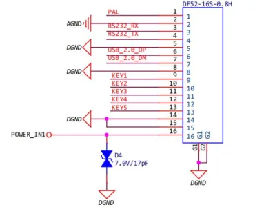
Budget normal, start-up, and peak power for the selected core and interface configuration, and design an appropriate thermal path. AeroMini specifies typical module consumption below 0.7 W; budget the interface kit, host and complete payload separately. The illustrated AeroMini POWER_IN1 and POWER_IN2 inputs require regulated 5 V only. Confirm polarity, ripple, transients, grounding and protection for the exact board before connecting any aircraft supply.
3. Optics, IFOV, and the Johnson Criteria for Airborne Game Recovery
Optical planning begins with field of view (FOV), instantaneous field of view (IFOV), and the number of sampled pixels across a specified visible dimension. Johnson-style Detection, Recognition, and Identification (DRI) terminology is useful for describing progressively more demanding tasks, but simple pixel counts do not establish a universal success probability. The geometric examples below use the CAMCUDA thermal imaging calculator conventions of 1.5, 6, and 12 pixels; these are planning assumptions, not validated wildlife-identification thresholds:
- ✅ Detection planning marker (1.5 pixels): A geometric marker for the presence of a small image feature; actual detection also depends on contrast, noise, optics, and the observer or algorithm.
- ✅ Recognition planning marker (6 pixels): A larger sampling allowance for a broad classification task; field validation must define the classes and acceptable error rate.
- ✅ Identification planning marker (12 pixels): A higher geometric sampling allowance; it does not prove species, age, sex, or antler detail and must not be used as a positive-identification guarantee.
For a small central detector pixel in an ideal rectilinear optical model, IFOV is approximately the pixel pitch divided by focal length. Keep the length units consistent:
IFOV (rad) ≈ p (mm) / f (mm); IFOV (mrad) ≈ p (µm) / f (mm)
Here, p is detector pixel pitch and f is focal length. At fixed focal length, a smaller pitch produces finer angular sampling, but usable detail still depends on optical contrast transfer, noise, focus, and processing. For a 12 µm pitch and a 9 mm lens, the central IFOV is approximately 1.333 mrad. Pixel sampling alone is not a measured system-resolution specification.
At range R, the central pixel footprint in a plane perpendicular to the optical axis is approximately R × IFOV in radians. This can represent ground sample distance (GSD) for a nadir camera over a flat surface; an oblique view or uneven terrain requires projection geometry, so slant range and flight altitude are not interchangeable:
Central pixel footprint (m) ≈ R (m) × IFOV (rad) = R (m) × IFOV (mrad) / 1000
Let Hc be the visible projected dimension of the subject in the same transverse plane. The table uses Hc = 0.5 m as an explicit hypothetical input, not a universal animal dimension. Partial occlusion or a different orientation can reduce the visible extent:
N ≈ Hc (m) / footprint (m) = 1000 × Hc (m) × f (mm) / [R (m) × p (µm)]
Shorter focal lengths cover a wider angle at a given sensor size, while longer focal lengths put more sampled pixels across the same visible dimension at the same range. For an ideal rectilinear lens, horizontal FOV = 2 × atan[W / (2f)] and vertical FOV = 2 × atan[H / (2f)], using sensor dimensions W and H in the same units as f. Actual lens distortion and measured FOV must be checked separately.
Use the geometric model to compare sampling and coverage, then specify the evidence needed for the civilian observation task: representative subject visibility, image quality, environmental conditions, and acceptable classification uncertainty. It does not set a wildlife-safe altitude, establish acoustic invisibility, or guarantee fine anatomical detail. Higher sampling cannot compensate for an obscured line of sight.
4. Video Interfaces, Latency, and Processing Pipelines
Evaluate video latency from scene acquisition through sensor readout, image processing, transport, host buffering, and display. The interface name alone does not specify that end-to-end delay. Define an acceptable measured latency and frame continuity for the intended observation workflow, then test the complete pipeline under representative processor and link load.
Here is how the primary interface architectures shake out in real airborne hardware builds:
Analog CVBS (Composite Video Baseband Signal): CVBS carries an analog video image for a compatible PAL/NTSC receiver or capture path. It can support a simple viewing pipeline, but sensor processing, frame timing, capture, and display still contribute to delay. Do not infer glass-to-glass latency from the interface alone. Verify video standard, levels, impedance, and measured end-to-end timing for the actual assembly. See our CVBS integration guide.
MIPI CSI-2: CSI-2 is a camera transport protocol, not a guarantee of calibrated temperature data. Confirm physical layer, lane configuration, pixel format, packing, timing, control interface and host driver. AeroMini can provide MIPI CSI-2 and USB UVC on the same module, but the selected non-radiometric version supplies imagery without calibrated temperatures. Standard RAW or minimally processed output is not supplied; it requires a separate customization assessment. A connector alone does not establish Jetson, Rockchip or Raspberry Pi compatibility, or sub-millisecond system latency.
USB Video Class (UVC): A compliant device can use a supported operating system’s UVC driver for its advertised modes. Verify resolution, frame rate, pixel format, bandwidth and host support. Vendor-specific controls may require additional software or UVC extension-unit handling. AeroMini USB video capability does not establish a USB serial-control channel; use the documented control path for the exact board. UVC has no universal end-to-end latency; measure the selected camera, host, application and display pipeline.
Other digital video interfaces: BT.656, BT.1120, SDI, and Camera Link describe different electrical or transport arrangements and are not interchangeable. If an RFQ requires one of them, request the exact output standard, supported image format, frame timing, connector, control protocol, and receiver requirements. A video output label does not establish native detector resolution, radiometric content, or automatic visible/thermal image registration.
5. Architectural Evaluation: 640×512 vs. 1280×1024 Sensor Architectures
Choosing between a 640×512 detector and a native 1280×1024 detector affects optical coverage, sampling, processing load, and packaging. The comparison below is a general architecture model. It assumes equal pixel pitch where physical sensor dimensions are compared and does not establish the availability or specifications of a particular 1280 module.
A native 1280×1024 array contains 1,310,720 pixels, exactly four times the 327,680 pixels in a 640×512 array. It has twice as many samples along each axis. This is a pixel-count comparison, not an unconditional fourfold improvement in resolved detail. At equal pitch, the detector is also twice as wide and twice as high, leading to two useful geometric comparisons:
First, at equal pitch, focal length, and perpendicular scene-plane range, an ideal 1280×1024 system retains the same central pixel footprint while covering twice the width and height, or four times the area, in that plane. Angular FOV is 2 × atan[sensor size / (2f)], so its angle is not generally doubled. These ideal footprint ratios do not imply a fixed reduction in survey time; overlap, terrain, visibility, flight constraints, and processing can limit usable coverage.
Second, at equal pitch, doubling focal length together with both array dimensions keeps the same ideal angular FOV and halves central IFOV. At the same range, a visible feature then spans twice as many sampled pixels; at twice the range, its approximate pixel count returns to the original value. This is a geometry relationship, not an altitude recommendation or a guarantee of wildlife identification or reduced animal disturbance.
A larger detector requires an adequate image circle, while lens aperture and mass depend on focal length, f-number, and design. Processing and transport requirements depend on the chosen output mode. As an illustrative uncompressed payload calculation, 1280 × 1024 × 16 bits × 50 frames/s = 1,048,576,000 bit/s, or 1.048576 Gbit/s, before protocol overhead. This arithmetic does not establish radiometry, a supported RAW output, or compatibility with a particular bus. Request current module, lens, interface-board, power, and mass documentation for either architecture.
6. Thermal drone for hunting: OEM specifications and sourcing checks
The comparison below separates a documented AeroMini 640 evaluation configuration from the evidence needed when a project requires a native 1280×1024 detector. The right-hand column is a sourcing checklist, not a second product specification. Match the selected sensor, lens, interface board and host to the lawful civilian observation or recovery application before ordering. Procurement contributors: Vivian, Lena and Sophie, Sales Managers.
| Engineering Parameter | CAMCUDA AeroMini 640 — 9 mm, non-radiometric, USB + CVBS + MIPI | Native 1280 × 1024 sourcing requirements |
|---|---|---|
| Native Thermal Resolution | 640 × 512 pixels | Require a native 1280 × 1024 detector; verify that the image is not upscaled |
| Pixel Pitch | 12 μm | Obtain the actual pixel pitch for like-for-like optical calculations |
| Detector Material | Uncooled VOx focal plane array | Request the detector technology and current manufacturer documentation |
| Spectral Range | 8–14 μm (LWIR) | Confirm the LWIR spectral response for the quoted detector and optics |
| Thermal Sensitivity (NETD) | ≤30 mK at 25 °C, F/1.0 | Request NETD with temperature, F-number and test conditions; validate scene performance |
| Frame Rate | 60 Hz default / 30 Hz factory option; confirm the selected output path | Specify the required frame rate and confirm it on the exact output, firmware and host |
| Module Weight (lens and flange excluded) | <20 g; complete payload mass must be measured separately | Obtain module mass and complete lens, board, cable and enclosure mass |
| Physical Dimensions (lens and flange excluded) | 21 × 21 × 28 mm; request complete assembly drawings | Request matched full-assembly drawings, mount details and cable clearances |
| Power Input for Documented Board | 5 V only at illustrated POWER_IN1 / POWER_IN2 pins; confirm board revision | Confirm the exact input pins, voltage limits, startup load and supply requirements |
| Power Consumption | Typical <0.5 W at 25 °C for the module; complete-kit consumption may differ | Request typical, startup and worst-case power for the complete configuration |
| Video Output Paths | Selected USB UVC + CVBS + MIPI package; confirm output format, rate and host | Confirm required native-resolution outputs, data format and host compatibility |
| Control Interfaces | 16-pin: RS232_RX/TX, voltage unspecified; 26-pin: UART TX/RX at 3.3 V | Request connector pinout, control protocol and electrical levels for the quoted board |
| Online Non-radiometric Lens Options | 4, 7, 9, 13, 18, 25, 35 and 50 mm; 9 mm selected | Obtain compatible lens options, specified FOV and full-assembly dimensions |
| Target Integration Class | OEM civilian observation and authorized recovery payload evaluation; not a complete drone camera | A separate sourcing path when native 1280 × 1024 resolution is mandatory |
Sourcing Profile 1: Native 1280×1024 Requirements for Civilian Observation Payloads
If the application requires native 1280×1024 thermal sampling, retain that requirement in the RFQ. Request detector-resolution evidence, actual pixel pitch, quoted lens focal length and specified field of view. A 640×512 module or an upscaled image does not satisfy a native 1280×1024 requirement. Compare coverage and sampling using matched optical assumptions and visible target dimensions, then validate the complete system in representative civilian observation conditions.
Request a current datasheet stating spectral response, NETD and its test conditions, supported frame rate on the intended output, and whether the configuration supplies calibrated temperature measurements. Obtain the mass, dimensions and power budget for the complete quoted assembly, including its lens, interface board, cables and enclosure. Detector resolution alone does not establish animal identification, visibility through foliage or suitability for a particular aircraft.
The RFQ should identify the host board and software version, required video format and data depth, control protocol and electrical levels, approved power input, connector orientation and matching mechanical files. Confirm whether RAW or radiometric output is actually supplied before designing the processing pipeline. Request export-classification, origin and other procurement evidence for the exact item and intended destination; a component name or frame rate does not establish legal eligibility. Use the contact request below to discuss these native-resolution requirements without substituting an unverified SKU.
Discuss Native 1280×1024 Requirements ➔
Product Profile 2: CAMCUDA AeroMini 640 — 9 mm Non-radiometric Evaluation Configuration
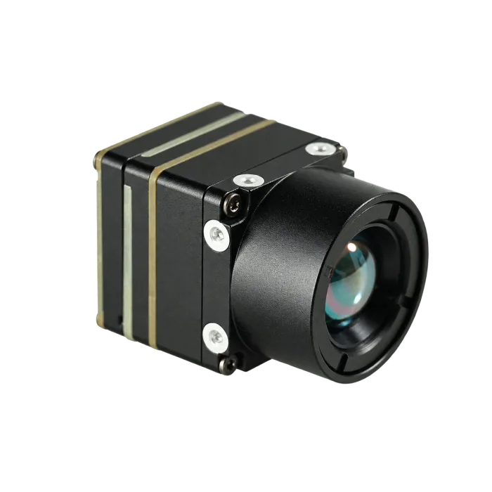
The CAMCUDA AeroMini 640 is an OEM integration module for compact civilian observation payloads. The configuration discussed here is non-radiometric, with a 9 mm lens and USB + CVBS + MIPI interface kit. Its uncooled VOx detector has 640×512 pixels, a 12 μm pitch and an 8–14 μm spectral response. The non-radiometric model has a 60 Hz default and a 30 Hz factory option; confirm the required output, firmware and host because the factory selection does not guarantee simultaneous 60 Hz output on every interface.
The manufacturer specifies NETD ≤30 mK at 25 °C, F/1.0, a module weight below 20 g and dimensions of 21×21×28 mm, with both lens and flange excluded. Typical module consumption is below 0.5 W at 25 °C; the complete kit and payload need separate mass and power budgets. The operating-temperature specification is −40 °C to +80 °C. The illustrated POWER_IN1 and POWER_IN2 pins are 5 V inputs only; do not apply 12 V or an aircraft battery bus to them. This non-radiometric version supplies thermal imagery, not calibrated temperature readings, and RAW or minimally processed output is not included as standard; request a separate customization assessment.
The table below compares five focal lengths using a hypothetical 640×512 array with 12 µm pitch. The focal lengths correspond to the current AeroMini option list, but the FOVs are ideal rectilinear calculations, not manufacturer-measured lens specifications. Distances use a fully visible 0.5 m projected dimension and the calculator’s 1.5, 6, and 12 pixel planning markers. They are geometric examples for requirements review, not measured detection, recognition, or identification ranges.
| Focal Length | Ideal FOV (H × V) | Central IFOV | 1.5-pixel Model Distance | 6-pixel Model Distance | 12-pixel Model Distance |
|---|---|---|---|---|---|
| 7 mm | 57.5° × 47.4° | 1.714 mrad | 194.4 m | 48.6 m | 24.3 m |
| 9 mm | 46.2° × 37.7° | 1.333 mrad | 250.0 m | 62.5 m | 31.3 m |
| 13 mm | 32.9° × 26.6° | 0.923 mrad | 361.1 m | 90.3 m | 45.1 m |
| 25 mm | 17.5° × 14.0° | 0.480 mrad | 694.4 m | 173.6 m | 86.8 m |
| 35 mm | 12.5° × 10.0° | 0.343 mrad | 972.2 m | 243.1 m | 121.5 m |
Model notes: FOV = 2 × atan(sensor dimension / 2f); IFOV ≈ p/f; distance R ≈ Hc × f / (N × p), with consistent length units. Calculations use full precision before rounding FOV to 0.1°, IFOV to 0.001 mrad, and distance to 0.1 m. The model excludes atmospheric loss, optical contrast transfer, noise, motion blur, occlusion, and processing effects; it assigns no success probability. Confirm actual lens FOV, focus, mechanical fit, and performance with the supplier.
View AeroMini 640 Configuration & Documentation ➔
7. Systems Engineering & Integration Checklist
Before releasing PCB fabrication runs, machining gimbal enclosures, or signing off on OEM purchase orders, engineering teams should execute this detailed system checklist:
-
1. Optical & Mission Flight Profile Validation:
- ⚙️ Define the lawful civilian observation task, required visibility, operating environment, and applicable wildlife-disturbance constraints; do not treat a geometric range as a flight instruction.
- ⚙️ Verify units, viewing geometry, visible projected subject extent, and sampling requirements; validate any classification claim with representative imagery and an explicit error criterion.
- ⚙️ Compare the current lens options using ideal FOV and sampling calculations, then confirm measured FOV, focus, distortion, and mechanical drawings.
- ⚙️ Request the lens material, transmission, coating, cleaning, and environmental-test documentation appropriate to the intended installation.
-
2. Gimbal Mechanics & Thermal Management:
- ⚙️ Calculate assembled center of gravity and inertia for the core, lens, boards, cables, mounts, and enclosure about each gimbal axis.
- ⚙️ Follow the supplier’s thermal mounting guidance and verify warm-up, steady-state temperature, and image uniformity in the assembled enclosure.
- ⚙️ Confirm connector and cable clearance, bend limits, movement range, strain relief, and the suitability of the selected vibration isolation.
- ⚙️ Validate payload mass, balance, inertia, and motor thermal loading against the required gimbal movement and stabilization conditions.
-
3. Electrical Power & Signal Interface Integrity:
- ⚙️ Confirm documented supply voltage, start-up and peak demand, ripple, transients, grounding and protection. AeroMini POWER_IN1 (16-pin pin 16) and POWER_IN2 (26-pin pins 12, 25 and 26) require 5 V only; do not apply 12 V.
- ⚙️ Select a documented video mode and compatible receiver; measure end-to-end latency and verify whether the output contains display video, uncalibrated samples, or calibrated temperature data.
- ⚙️ Verify the exact pinout, electrical levels and command protocol. The 16-pin board labels RS232_RX/TX at pins 3/4 without specifying voltage levels; the 26-pin board lists UART TX/RX at pins 19/20 at 3.3 V. These boards are not interchangeable, and USB video does not imply USB serial control.
- ⚙️ Review grounding, cable routing, shielding, and filtering with the relevant hardware guidance, then test electromagnetic compatibility in the intended assembly.
-
4. Regulatory Compliance, Software, & Supply Chain:
- ⚙️ Verify applicable export controls for the exact product classification, destination, end user, and end use; frame rate alone does not establish an exemption. Consult current BIS classification guidance where the EAR applies.
- ⚙️ Request current, model-specific origin and supply-chain documentation and assess procurement requirements for the complete system. Obtain matching mechanical drawings for the ordered 9 mm assembly; the published AeroMini STEP file represents a 7 mm version and is not complete 9 mm assembly CAD.
- ⚙️ Verify the exact host, operating system, video mode, firmware, driver or SDK version and required controls. Consult the current AeroMini product PDF and the official technical documentation folder, which lists USB-SDK.zip and the AeroMini 640/CV serial-port guide. Documentation availability does not establish compatibility with every host.
8. Deep-Dive Frequently Asked Questions
Are thermal imaging drones legally compliant for hunting and wildlife recovery operations?
Legality depends on the exact jurisdiction, species, and mission. Before deployment, verify the applicable aviation and wildlife rules, airspace restrictions, land-access permissions, and any required agency authorization. In the United States, FAA flight authorization does not replace wildlife or land-use permission; see the FAA guidance on state and local authority.
Post-shot game recovery may also be restricted or prohibited, as illustrated by Texas Parks & Wildlife’s drone guidance. Invasive-species work is not automatically authorized. Confirm the proposed activity with the responsible wildlife agency before operating. A higher-resolution thermal sensor does not establish legal permission for a mission.
What are the primary optical and resolution trade-offs between 640×512 and 1280×1024 cores for aerial game recovery?
A native 1280×1024 array has four times the pixel count of a 640×512 array. At equal pixel pitch, focal length, and perpendicular scene-plane range, ideal coverage is twice as wide and twice as high while central pixel footprint remains the same. Angular FOV follows an arctangent relationship and is not generally twice as large. Alternatively, doubling focal length with the larger array preserves ideal angular FOV and halves central IFOV.
These geometric comparisons do not guarantee species identification, survey-time savings, or an altitude that avoids disturbing animals. Compare the complete lens, module, interface, power, and mass requirements using current documentation. An illustrative 1280×1024, 16-bit, 50-frame/s stream contains 1.048576 Gbit/s of uncompressed pixel payload before overhead; neither radiometry nor support for that output follows from array size.
How does microbolometer NETD sensitivity affect wildlife detection through tree canopies?
Lower NETD can help reveal weak thermal contrast under comparable test conditions, but it does not enable a camera to see through opaque foliage or wood. A gap may reveal part of the subject; the available detail then depends on the visible extent, optics, contrast, weather, noise, and processing.
NETD is a sensitivity metric, not a guaranteed temperature-measurement accuracy or a species-identification threshold. Although 30 mK is a temperature interval of 0.03°C, a 30 mK specification does not guarantee detection of every feature at that contrast. Use representative tests of the full system, including partial occlusion; NUC and display processing cannot reconstruct a subject signal blocked from the camera.
📚 References & Further Reading
- Optical and sensitivity principles: See LYNRED’s detector range and contrast-transfer discussion and FLIR’s NETD explanation. These general sources do not validate a CAMCUDA wildlife-identification range.
- Related Guide: Hardware wiring, signal protocols, and video transmission in our guide on CVBS thermal camera module analog video integration.
- Technical Knowledge Base: Deep-dive sensor physics, radiometric calibration, and lens calculations in the CAMCUDA Thermal Imaging Guides.
- Component Sourcing: Full OEM thermal cores, uncooled LWIR modules, and lens configurations in the CAMCUDA Product Catalog.