Best IR Camera for OEM Integration: Engineering Guide to LWIR Cores & Sensor Selection
Best IR Camera for OEM Integration: Engineering Guide to LWIR Cores & Sensor Selection
Specifying the best IR camera for OEM optronics, unmanned aerial systems (UAS), automated guided vehicles (AGVs), and industrial observation starts with separating active near-infrared (NIR) imaging from passive long-wave infrared (LWIR) thermal imaging. Vendor datasheets can blur these different technologies.
An unsuitable waveband, lens or video path can leave a system short of useful scene detail in darkness, fog or industrial aerosols. Define the lighting, weather, inspection task and allowable end-to-end latency before comparing camera cores.
For aerial inspection and industrial automation builds, your hardware choices must fit the Size, Weight, Power, and Cost (SWaP-C) envelope. Spatial sampling, thermal sensitivity, dynamic range and drift stability also need to match the application; no single resolution or NETD value guarantees success.
This guide breaks down thermal radiation, microbolometer readout, optical IFOV math, dual-spectrum edge processing and practical integration. It compares a standalone LWIR core with a visible-plus-thermal AI platform so you can select the best IR camera architecture for your host and inspection requirements.
Table of Contents
- 👉 1. Spectral Discrimination: Reflected-Light NIR/SWIR vs. Passive LWIR
- 👉 2. Microbolometer Architecture: VOx vs. a-Si & NETD Benchmarks
- 👉 3. Optical Engineering: IFOV, Germanium Lenses & Johnson’s Criteria
- 👉 4. Dual-Spectrum Imaging & On-Module Edge AI
- 👉 5. Best IR Camera Comparison: Standalone Thermal Core vs Dual-Spectrum AI
- 👉 6. Electrical, Thermal & Mechanical Integration Guidelines
- 👉 7. Deep-Dive OEM Engineering FAQ
1. Spectral Discrimination: Reflected-Light NIR/SWIR vs. Passive LWIR
When you sit down to select an IR camera engine for an autonomous rig or a ruggedized pan-tilt surveillance head, the first step is sorting out the operational waveband, the underlying photon physics, and the atmospheric transmission windows. The infrared spectrum isn’t a monolith. Named band boundaries are conventions, while absorption by water vapor (H2O), carbon dioxide (CO2), ozone (O3) and other gases shapes atmospheric transmission windows.
Look at how standard optoelectronic sensor classes compare across operational bands:
| Infrared Band | Typical Imaging Waveband (μm) | Operating Principle | Atmospheric Transmission & Constraints |
|---|---|---|---|
| Near-Infrared (NIR) | Approximately 0.75–1.0 for common silicon-camera examples | Reflected-light detection with silicon CMOS; ambient or active illumination | 850/940 nm LEDs are common for dark scenes. Fog and aerosols can scatter illumination; reflectors can cause glare. |
| Short-Wave Infrared (SWIR) | Approximately 1–2.5; detector cutoff varies | Primarily reflected-light imaging; InGaAs is one detector technology | Can use ambient light, nightglow or active illumination. Haze performance depends on wavelength and atmosphere; water-absorption bands matter. |
| Mid-Wave Infrared (MWIR) | Common thermal-imaging window: 3–5 | Thermal-radiation detection; cooled photon detectors are common | Cooling requirements depend on detector design. Atmospheric transmission, sensitivity, power and service needs require system-specific evaluation. |
| Long-Wave Infrared (LWIR) | Common thermal-imaging window: 8–14 | Thermal-radiation detection with uncooled VOx or a-Si microbolometers, among other designs | Passive imaging can work without visible light. Humidity, fog, smoke and dust can still reduce contrast or transmission; LWIR is not immune to obscurants. |
Active NIR camera rigs commonly use silicon CMOS sensors with suitable NIR transmission and 850 nm or 940 nm illumination. They can be a practical low-cost option when reflected-light detail is useful. Illumination geometry, source power, surface reflectance and exposure determine the usable image.
Fog, dust and industrial exhaust can scatter the outgoing and returning light and create backscatter glare. Neither NIR nor SWIR should be treated as active-only: available ambient illumination and the detector’s spectral response also matter.
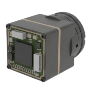
Passive Long-Wave Infrared (LWIR) systems operating in the 8.0 μm to 14.0 μm window operate on completely different physics. Per Planck’s Radiation Law, any real-world object with a temperature above absolute zero emits electromagnetic radiation. For an ideal blackbody between −40°C and +80°C (roughly 233 K to 353 K), the wavelength-domain emission peak sits in the LWIR spectrum, governed by Wien’s Displacement Law. Real-surface spectra also depend on spectral emissivity:
λmax = b / T ≈ 2898 μm·K / 300 K ≈ 9.66 μm
Because near-ambient objects emit strongly in the LWIR region, an LWIR core can form thermal images without artificial illumination. The image depends on emitted and reflected infrared radiation, surface emissivity, optics and the atmosphere, rather than visible brightness alone.
There is no blanket guarantee of visibility through fog, smoke or dust, and intense radiation or reflections can still affect an image. For practical industrial installations, see our guide on uncooled LWIR thermal modules for outdoor security and industrial monitoring.
2. Microbolometer Architecture: VOx vs. a-Si & NETD Benchmarks
Uncooled LWIR camera cores rely on a micro-machined MEMS focal plane array (FPA) known as a microbolometer. Photon detectors generate an electrical response from absorbed photons, while microbolometers are thermal detectors. When incident LWIR radiation strikes an absorber membrane, its temperature climbs, shifting its internal electrical resistance. That resistance delta is measured and converted into digital counts by the underlying Readout Integrated Circuit (ROIC).
For manufacturer background on microbolometer principles, see Sofradir/LYNRED’s uncooled infrared imaging white paper. Product specifications still need to be checked against the selected module’s documentation.
A typical pixel in an uncooled FPA uses a microscopic absorbing plate suspended over the silicon ROIC substrate by tiny lithographic legs. These legs pull double duty: they form the electrical path for signal readout and provide high thermal isolation (ultra-low thermal conductance, G), keeping pixel heat from bleeding into neighboring detectors or the backplane substrate. One material property is the Temperature Coefficient of Resistance (TCR), defined at the operating temperature in K−1 or %/K; it does not by itself establish camera sensitivity:
TCR = α = (1 / R) · (dR / dT)
In the optronics shop today, two core material technologies dominate the uncooled market:
- ⚙️ Vanadium Oxide (VOx): VOx is widely used as a temperature-sensitive resistive material in uncooled microbolometers. TCR and noise depend on the film and fabrication process. Compare measured camera NETD under stated conditions instead of inferring performance from the material name.
- ⚙️ Amorphous Silicon (a-Si): a-Si is another established microbolometer material. Process design, thermal isolation, readout, optics and image processing influence final sensitivity. A material label alone does not justify a universal NETD ranking, cost advantage or image-quality verdict.
Noise Equivalent Temperature Difference (NETD) Benchmark
NETD is the defining metric for thermal sensitivity. It represents the smallest temperature difference between a target and its background that generates a signal equal to the RMS noise floor of the camera system (an SNR of 1). The relationship is expressed as:
NETD = σS / |dS/dTBB|
Here σS is the measured RMS output noise and |dS/dTBB| is the local output response to blackbody temperature, measured in matching signal units per kelvin and operating conditions. Their ratio is in kelvin; responsivity must not be multiplied in a second time.
Compare NETD at the same scene and camera temperature, lens F-number, frame rate or integration time, noise bandwidth and processing settings. NETD is a noise-equivalent contrast measure, not an absolute temperature-accuracy specification or a guarantee of resolved detail. For the best IR camera shortlist, ask for those test conditions before comparing a single mK number. See LYNRED’s definition of NETD.
3. Optical Engineering: IFOV, Germanium Lenses & Johnson’s Criteria
Infrared optical design differs from visible lens design. Standard optical glasses such as BK7 and fused silica are unsuitable for an 8–14 μm imaging path. Suitable materials include germanium, zinc selenide and selected chalcogenide glasses; material transmission must match the operating band.
Manufacturing may use grinding, polishing, diamond turning or molding, depending on the material and design. Anti-reflection coatings, environmental protection, focus stability and optical quality must be specified for the assembly; neither diamond turning nor a particular hard coating is universal.
To compare the best IR camera lens options for a defined inspection scene, calculate the Instantaneous Field of View (IFOV). IFOV defines the angle subtended by a single pixel element in object space. The following expression is the small-angle approximation; using micrometers for pitch and millimeters for focal length gives milliradians:
IFOV (mrad) ≈ [ Pixel Pitch d (μm) / Optical Focal Length f (mm) ]
Total horizontal (HFOV) and vertical (VFOV) angles are estimated from detector pixel count and focal length for an ideal rectilinear lens. In these arctangent formulas, express pixel pitch d and focal length f in the same length unit; convert 12 μm to 0.012 mm when f is in millimeters. Convert the resulting angles to degrees as needed:
HFOV = 2 · arctan [ (Nh · d) / (2 · f) ] | VFOV = 2 · arctan [ (Nv · d) / (2 · f) ]
Johnson’s Criteria & Practical Sampling Limits
Johnson-style detection, recognition and identification criteria are historical task-performance models, not universal pixel thresholds or guaranteed operating ranges. Their application depends on the task, contrast, optics, observer or algorithm, and test method. For OEM inspection, first state what physical feature needs to be visible and validate it in representative imagery:
- ✅ Detection: Establish whether a relevant anomaly is present in the inspection scene.
- ✅ Recognition: Establish whether the available detail supports a defined category, such as one component type versus another.
- ✅ Identification: Establish whether the image supports the specific detail required by the inspection procedure. Set acceptance criteria with representative samples rather than assuming a fixed pixel count guarantees success.
For preliminary geometry, an object of width W at distance R spans approximately N pixels when the angles are small:
Npixels ≈ W / [ R · IFOV (radians) ] | Pixel footprint ≈ R · IFOV (radians)
The following calculated examples use a 640×512 array with 12 μm pitch, an ideal rectilinear lens and a perpendicular scene plane at 10 m. They describe geometry only, not a specific product’s available lenses or guaranteed resolved detail. Actual lens distortion, cropping and quoted FOV may differ:
| Example Focal Length | Calculated FOV (H×V) | IFOV | Pixel Footprint at 10 m | Scene Width at 10 m | Pixels across a 100 mm Feature at 10 m |
|---|---|---|---|---|---|
| 4.9 mm | 76.17° × 64.17° | 2.449 mrad | 24.49 mm | 15.673 m | 4.08 px |
| 9.1 mm | 45.76° × 37.31° | 1.319 mrad | 13.19 mm | 8.440 m | 7.58 px |
| 13.0 mm | 32.91° × 26.59° | 0.923 mrad | 9.23 mm | 5.908 m | 10.83 px |
| 19.0 mm | 22.85° × 18.37° | 0.632 mrad | 6.32 mm | 4.042 m | 15.83 px |
| 35.0 mm | 12.52° × 10.03° | 0.343 mrad | 3.43 mm | 2.194 m | 29.17 px |
For the focal-length/FOV relationship, see Edmund Optics’ field-of-view guide. For preliminary lens and scene-coverage checks, use the thermal imaging calculator with supported inputs. A geometric result does not predict detection probability, AI recognition performance or temperature accuracy. Confirm the selected lens and output mode, then test the required detail at the intended working distance.
4. Dual-Spectrum Imaging & On-Module Edge AI
Dual-spectrum payloads combine visible Electro-Optical (EO) imaging with LWIR imaging. In daylight, a visible sensor can provide fine spatial detail and color context. LWIR adds thermal contrast without requiring visible illumination. Each channel has limits, and weather or low thermal contrast can still obscure useful detail.
An embedded processing board can combine these feeds, but it does not require one universal CPU model or a dual-MIPI architecture. CAMCUDA AI VisionCube DT Pro is a current example with dual visible cameras, 640×512 thermal imaging and 6 TOPS AI processing. TOPS describes a processing-capacity specification, not a guaranteed frame rate, latency or number of tracks.
When choosing the best IR camera platform with onboard AI, separate documented functions from the acceptance tests your application still needs:
- ⚙️ Picture-in-Picture and Fusion: VisionCube documentation lists picture-in-picture. PIP alone does not establish pixel-registered fusion; alignment, parallax, timing and any blended overlay must be verified for the exact assembly.
- ⚙️ Thermal Correction: Confirm the selected thermal camera’s NUC/FFC behavior and any interruption to delivered video. An AI-processing rating does not establish shutterless correction or uninterrupted frames.
- ⚙️ AI Model Performance: Verify the supplied model, input resolution, preprocessing, accuracy and sustained throughput on representative civilian inspection scenes. Measure end-to-end latency, including acquisition and display.
- ⚙️ Feature Validation: Confirm which detection or tracking functions are supplied and test their behavior under scene changes. Supplier demonstration overlays are not guaranteed distance, speed, track-count or minimum-object specifications.
- ⚙️ Host Integration: Request the VisionCube-specific AI interface guide, connector definition, electrical levels, protocol and example output. Do not infer CRSF, MAVLink, autopilot compatibility or control behavior from a product-family name.
5. Best IR Camera Comparison: Standalone Thermal Core vs Dual-Spectrum AI
To help you evaluate architecture options during engineering trade studies, here is a direct comparison between an ultra-low SWaP standalone microbolometer core and an integrated dual-spectrum AI tracking platform.
| Engineering Parameter | CAMCUDA AeroMini 640 Standalone LWIR Core | CAMCUDA AI VisionCube DT Pro Dual-Spectrum AI Platform |
|---|---|---|
| Detector Architecture | Uncooled VOx thermal core | Dual visible cameras plus an LWIR thermal camera; confirm final camera BOM |
| Thermal Array Resolution | 640 × 512 pixels | 640 × 512 pixels |
| Visible Video Resolution | N/A (Thermal Only) | 1920 × 1080 at 30 Hz; dual-visible specification |
| Thermal Pixel Pitch & Spectral Band | 12 μm | 8–14 μm | 12 μm | 8–14 μm |
| Thermal Frame Rate & NETD | Non-radiometric: 60 Hz default / 30 Hz factory option. Radiometric: 25 Hz by enquiry. NETD ≤30 mK at 25 °C, F/1.0 | 50 Hz thermal. Obtain NETD and test conditions for the selected configuration |
| Onboard Processing | Thermal camera processing; no AI-inference capability asserted here | 6 TOPS AI processing; CPU model and workload performance require confirmation |
| Latency & Performance Evidence | Measure the complete selected video path with the host | Request workload-specific latency and track-capacity evidence; measure the complete application |
| Video & Control Interfaces | USB + CVBS + MIPI and Type-C + CVBS are distinct tailboards; confirm format, rate and control guide | Thermal-camera component: USB. Request the DT Pro AI/host interface guide; do not apply AeroMini pinouts or SDK |
| Power Input & Consumption | Board-specific supply. Illustrated POWER_IN1/POWER_IN2: 5 V only. Typical module power <0.5 W at 25 °C; complete kit may differ | Common processing-board reference: 9–16 V input; confirm complete-kit power and startup requirements |
| Dimensions & Mass Scope | 21 × 21 × 28 mm; <20 g, excluding lens and flange | Common board: 38 × 38 × 29 mm; 43.8 g; 25.5 × 25.5 mm mounting. These are not complete-assembly dimensions or mass |
Product Showcase: CAMCUDA AeroMini 640 Standalone LWIR Core
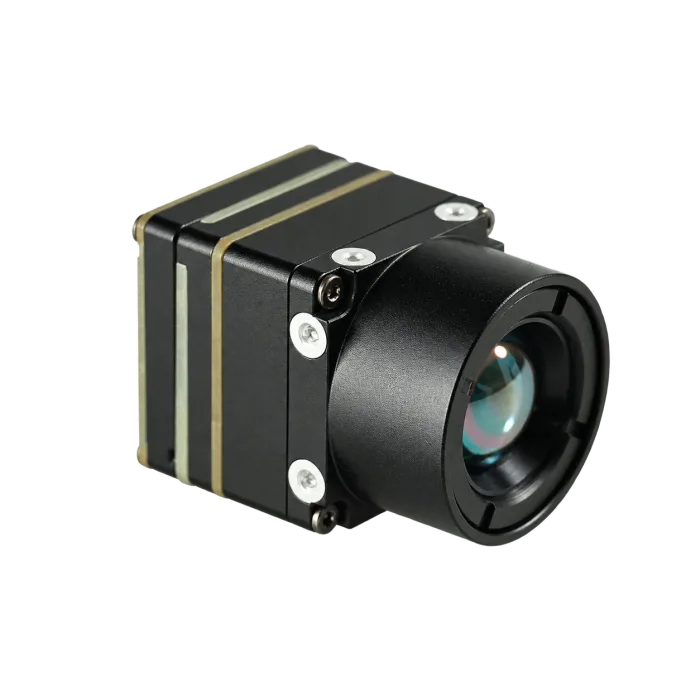
CAMCUDA AeroMini 640 Compact OEM Thermal Core
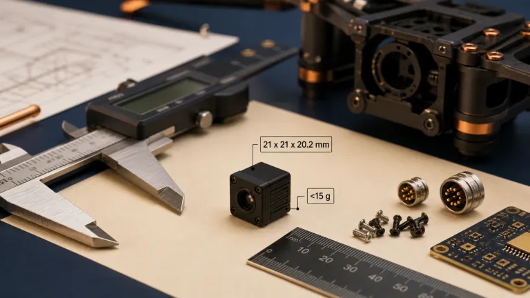
The CAMCUDA AeroMini 64060 Hz imaging is a standalone 640×512 uncooled VOx core with 12 μm pitch and NETD ≤30 mK at 25 °C, F/1.0. Non-radiometric imaging is 60 Hz by factory default or 30 Hz by factory configuration; it does not measure temperature. The radiometric version is 25 Hz and currently enquiry-only.
Published core dimensions are 21 × 21 × 28 mm and mass is <20 g, both excluding lens and flange. Typical module consumption is <0.5 W at 25 °C; the lens, tailboard, cable and host must be included in the complete payload and power budget. The photo above shows the 9 mm assembly.
The best IR camera lens depends on scene coverage and required detail. AeroMini’s current product documentation lists the following selection points; confirm the lens, camera version, interface and configuration-specific price before ordering:
- ✅ 9 mm evaluation option: Documented 48.7° × 38.6° FOV. Non-radiometric selection; radiometric availability by enquiry.
- ✅ 4 mm or 7 mm wider views: Documented FOVs are 100° × 82° and 64° × 52°, respectively. Check distortion, near-focus needs and required feature sampling.
- ✅ 13 mm or 18 mm: Documented FOVs are 31.9° × 25.7° and 24.2° × 19.5°. These, with 9 mm, are the documented radiometric enquiry options.
- ✅ 25 mm: Documented 17.5° × 14° FOV. Confirm complete lens dimensions, mass and focus behavior.
- ✅ 35 mm or 50 mm narrower views: Documented FOVs are 12.5° × 10° and 8.8° × 7°. Validate scene coverage and optical detail rather than assuming a detection range.
- ✅ Other lens enquiries: The lens table also lists 15, 60 and 75 mm for enquiry. Listed geometry does not establish current stock, radiometric availability or a complete assembly specification.
USB + CVBS + MIPI and Type-C + CVBS are separate tailboard configurations. The USB + CVBS + MIPI kit includes a cable that requires customer soldering; the Type-C kit uses its own board and cable guide. Confirm supported video formats, delivered rates, simultaneous outputs and serial electrical levels for the supplied board and firmware. Neither interface naming nor a connector shape establishes universal host compatibility.
Product Showcase: CAMCUDA AI VisionCube DT Pro with Dual Visible and 640 Thermal Imaging
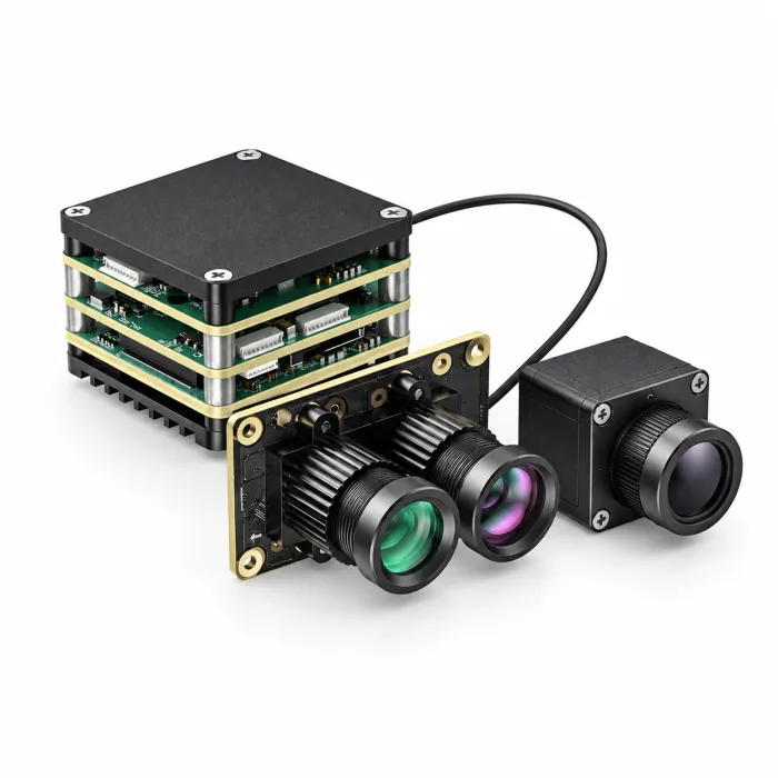
CAMCUDA AI VisionCube DT Pro
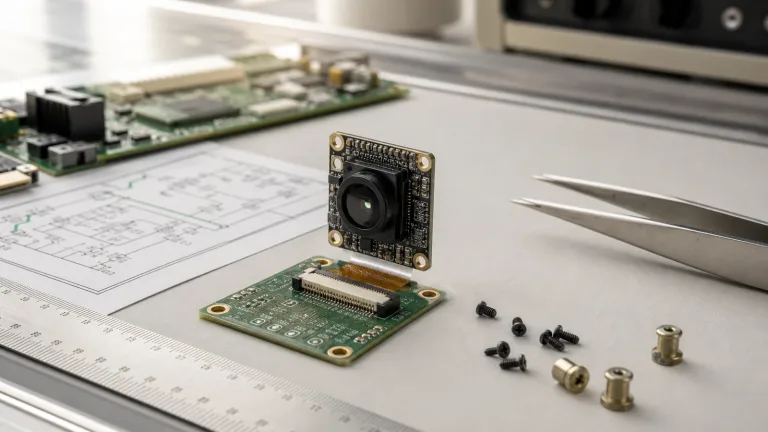
The CAMCUDA AI VisionCube DT Pro combines dual visible cameras, 6 TOPS AI processing and a 640×512 thermal camera at 50 Hz. Visible output is 1920×1080 at 30 Hz. The wide-angle visible lens is 3.9 mm; the telephoto visible lens is 12 mm. The thermal camera has 12 μm pitch and 9.1 mm optics.
The illustration above shows this multi-component arrangement. Component dimensions do not describe the assembled kit, and a product illustration is not a mechanical assembly drawing.
For civilian inspection and observation, evaluate the supplied software and AI interface against your own scenes. The current listing does not establish a CPU model, end-to-end latency, simultaneous-track capacity, minimum object size or guaranteed operating speed. PIP support does not prove calibrated image registration.
The DT Pro selection currently permits online checkout. Confirm the included cameras, processing board, cables, software, complete assembly, configuration-specific price and dispatch schedule; an enabled checkout does not state an inventory quantity or promise immediate dispatch.
| Subsystem | Parameter | Documented Value / Integration Check |
|---|---|---|
| AI & Processing | AI capacity | 6 TOPS; application throughput and model performance require testing |
| Display mode | Picture-in-picture is documented; verify alignment, timing and supplied controls | |
| AI interface | Request the DT Pro-specific protocol, connector/electrical guide and example data | |
| Visible Cameras (EO) | Optics / Component Dimensions | 3.9 mm wide + 12 mm telephoto; visible-camera component: 40.8 × 25 × 26 mm |
| Output / FOV / Sensitivity | 1920×1080 at 30 Hz; wide 72° H × 45° V; telephoto 26° H × 15° V. Supplied sensitivity: 9650 mV/lux·s, not a minimum-illumination lux rating | |
| Thermal Camera (LWIR) | Array / Optics / Interface | 640×512 at 50 Hz; 12 μm pitch; 8–14 μm; 9.1 mm optics; USB |
| FOV / Component Dimensions / Mass | 45.9° H × 36.9° V; 26 × 26 × 21.1 mm; ≤23 g, excluding lens and connectors | |
| Common Processing Board | Input / Dimensions / Mounting / Mass | 9–16 V; 38 × 38 × 29 mm; 25.5 × 25.5 mm mounting; 43.8 g. Board references only, not complete kit values |
Integration Note: The supplied brochure contains conflicting 1/2.8-inch and 1/2.6-inch CMOS entries for the dual-visible description; request the final camera BOM rather than selecting one as settled. Calibrated temperature-measurement range and accuracy are not established for DT Pro. Review the VisionCube specifications and request its matching software/interface package. AeroMini SDK resources and connector diagrams do not apply to this platform.
6. Electrical, Thermal & Mechanical Integration Guidelines
Integrating uncooled microbolometer cores and dual-spectrum AI platforms into real-world airborne, vehicular, or maritime chassis requires rigorous mechanical, thermal, and electrical practices. Validate the full assembly: an otherwise suitable core can perform poorly if supply noise, heat flow, mounting or host processing is unsuitable.
1. Power Supply Conditioning & Inrush Current Management
Power-supply noise can affect camera performance, so obtain the selected board’s input-voltage range, ripple tolerance and decoupling recommendations. Measure the supply at the module under representative load. Choose regulation, filtering and protection from the matched electrical requirements; do not assume a universal ripple limit.
Measure startup current, peak load and steady-state consumption for the complete configuration. A standalone thermal core and a VisionCube AI processing board have different requirements; do not assume a fixed inrush multiplier or startup window. Size the supply and local decoupling to the measured transient and the manufacturer’s guide.
2. Thermal Dissipation & Isothermal Mechanical Baseplates
Thermal gradients from nearby electronics can affect microbolometer stability and introduce image non-uniformity. Separate heat sources where practical, and evaluate warm-up, temperature transitions, self-heating and correction behavior in the actual enclosure. Component-level operating temperatures are not a complete-system thermal qualification.
For the best IR camera integration, define the enclosure temperature range and validate these thermal and mechanical choices:
- ⚙️ Select mounting material, contact area and fastening from the matched mechanical drawing and thermal design. A specific aluminum grade is not a universal requirement.
- ⚙️ Choose any thermal interface material from contact pressure, electrical isolation, allowable temperature, assembly tolerances and heat-flow needs; confirm compatibility with the camera housing.
- ⚙️ Provide appropriate heat paths for processing electronics and assess gradients near the thermal camera and lens. Verify optical alignment, cable strain relief and vibration behavior on the complete assembly.
3. Non-Uniformity Correction (NUC) and Shutterless Operation
Microbolometer output can drift as camera temperature changes. Non-Uniformity Correction (NUC) compensates pixel-response differences; Flat-Field Correction (FFC) may use a uniform reference such as an internal shutter, depending on the design. Gain calibration, offset updates and shutter behavior should not be treated as the same operation.
For continuous industrial monitoring, ask which correction modes the selected hardware and firmware support, what triggers a correction and whether video pauses. Measure interruptions in the delivered stream. Do not assume a fixed freeze duration or a configurable shutterless mode. The AeroMini product FAQ can guide a configuration-specific NUC/FFC enquiry; obtain separate confirmation for VisionCube DT Pro.
4. Regulatory Compliance & Supply Chain Documentation
For industrial, aerial-inspection or critical-infrastructure procurement, request origin, supplier and destination-market documentation for the exact configuration. Review applicable legal and procurement requirements with qualified support; a product description or origin statement does not guarantee compliance. Our guide on NDAA thermal camera module documentation and RFQ requirements outlines documents to request.
AeroMini Electrical Reference and Matched Assembly Documents
The following references apply only to the illustrated AeroMini USB + CVBS + MIPI tailboard, not the separate Type-C + CVBS board or VisionCube DT Pro. Match the board revision, physical connector orientation and full signal table before wiring. The schematic labels RS232_RX and RS232_TX; confirm electrical levels and any required transceiver before connecting a TTL-level UART.
The 16-pin POWER_IN1 and the separate 26-pin guide’s POWER_IN2 are 5 V inputs; do not apply 12 V. A family-level voltage entry does not override these pin-specific limits.
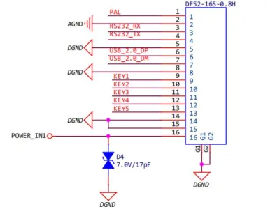
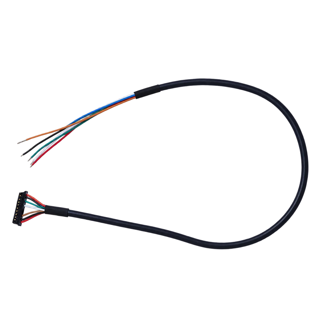
Consult the AeroMini FAQ for Linux drivers, examples and SDK resources, then confirm the supplied board, firmware, host, format and rate. These are AeroMini resources, not a verified SDK test result or a VisionCube software package.
The four-page AeroMini datasheet has no dimensioned assembly drawing. Request matched CAD for the ordered lens and tailboard; the separate 7 mm STEP reference does not cover every assembly. Request complete VisionCube DT Pro assembly dimensions and its own interface and software guides independently.
7. Deep-Dive OEM Engineering FAQ
What is the primary physical difference between an active NIR night vision camera and a true LWIR thermal IR camera?
NIR cameras form images from reflected near-infrared light, supplied by ambient illumination or an active source such as 850/940 nm LEDs. Active illumination performance depends on power, geometry, reflectance and exposure; fog or dust can create backscatter and glare.
LWIR cameras detect thermal-band radiation and can image without visible illumination. Emissivity, reflections, atmospheric transmission and scene contrast still matter. Passive operation does not guarantee visibility through obscurants or temperature-measurement capability.
How should I compare 256×192 and 640×512 thermal cores for the required scene detail?
A 640×512 array has 327,680 pixels versus 49,152 for 256×192, or about 6.67 times the total pixel count. At the same horizontal FOV it provides 2.5 times as many horizontal samples; at the same vertical FOV the ratio is about 2.67. The differing aspect ratios must be considered when matching coverage.
Total pixel count is not a linear sampling-density or range multiplier. Compare lens/FOV, pixel footprint on the required feature, optical resolution, NETD conditions, frame rate, processing and cost. A lower-resolution core may be adequate when its sampled detail meets the task; validate representative scenes rather than assuming it must fail.
Can a dual-spectrum AI tracking module be utilized directly for industrial radiometric temperature inspection?
Only if the exact configuration includes documented radiometric calibration and a supported temperature-data output. A contrast-enhanced display, color palette, NETD rating or onboard AI capability does not establish temperature accuracy.
VisionCube DT Pro’s current documentation does not establish calibrated temperature range or accuracy. AeroMini’s non-radiometric version does not measure temperature; its radiometric 25 Hz version is available by enquiry, with documented 9/13/18 mm lens options. Request calibration, accuracy conditions, emissivity/reflection compensation, data format and an acceptance test. For general measurement principles, see FLIR’s radiometry setup guidance; it does not establish CAMCUDA radiometric specifications.
What electrical and communication checks are needed when pairing a dual-spectrum module with a host controller?
Request the exact module and board revision, connector orientation, pin assignments, approved input voltage, startup/current budget, signal direction, serial electrical levels and host protocol. VisionCube’s common processing-board reference is 9–16 V, while the illustrated AeroMini POWER_IN1/POWER_IN2 pins are 5 V only; these references are not interchangeable.
Obtain the VisionCube DT Pro-specific AI interface guide and software examples, then test communications on a bench before system integration. A serial connector does not establish CRSF, MAVLink, BetaFlight or ArduPilot compatibility. The best IR camera for your project must fit the documented host interface as well as the imaging task; use a separate configuration-specific guide for AeroMini.
📚 References & Further Reading
- Radiation and Sensitivity References: NIST radiation constants and LYNRED’s NETD definition
- Optics and Measurement Background: Edmund Optics’ field-of-view guide and FLIR’s radiometry setup guidance
- Related Guide: Uncooled LWIR Thermal Modules for Outdoor Security and Industrial Monitoring
- Related Guide: NDAA Thermal Camera Module Documentation and RFQ Requirements
- Current Product Documentation: AeroMini 64060 Hz imaging and AI VisionCube DT Pro specifications; confirm configuration, documents and acceptance criteria before ordering.