How to Select the Best Thermal Camera: Engineering & Sourcing Guide
How to Select the Best Thermal Camera: Engineering & Sourcing Guide
Selecting the best thermal camera for industrial inspection, defense payloads, perimeter surveillance, or embedded OEM integration requires cutting straight through marketing fluff and getting down to the raw optoelectronic physics. In the Long-Wave Infrared (LWIR, 8–14 µm) band, performance isn’t decided by fancy spec-sheet bullet points. It’s dictated by hard optical and semiconductor realities: detector chemistry, microbolometer pixel pitch, thermal sensitivity (Noise Equivalent Temperature Difference, or NETD), lens aperture (F-number), optical transmission, and hardware-level signal processing latency. Sourcing engineers and electro-optical designers have to balance these core parameters against tough real-world constraints—shock, vibration, wide thermal swings, and stringent supply-chain compliance.
Look, in high-stakes condition monitoring and remote tactical deployments, an under-specified sensor subsystem will burn you every single time. You end up with flooded alarm logs from false triggers, useless spatial resolution at target stand-off distances, and budget-killing redesign cycles midway through system integration. This engineering and sourcing guide lays out a battle-tested blueprint for evaluating uncooled Vanadium Oxide (VOx) thermal imaging systems. From optical reach modeling using Johnson’s criteria and high-speed digital interface design (MIPI, USB, DVP, GigE) to requirements for complete handheld units and long-range observation platforms, here are the exact technical metrics you need to specify, benchmark, and procure the right thermal camera for your system.
Table of Contents
- 👉 1. Core Sensor Parameters: Microbolometer Architecture & Physics
- 👉 2. Optical Engineering: Focal Length, Aperture, and DRI Range Modeling
- 👉 3. Digital Video Pipelines, Interfaces, and Machine Vision Standards
- 👉 4. Field Hardware: Handheld & Long-Range Observation Systems
- 👉 5. Compliance, Regulatory Verification, and Sourcing Best Practices
- 👉 6. Engineering FAQ & Technical Diagnostics
1. Core Sensor Parameters: Microbolometer Architecture & Physics
Here’s the deal with thermal imaging cores: everything starts and ends with detector physics. The primary imaging engine of an uncooled thermal camera is the Focal Plane Array (FPA). In an uncooled microbolometer, an array of microscopic, thermally isolated pixel membranes absorbs incoming LWIR radiation. That absorbed photon energy heats the membrane, driving a measurable change in electrical resistance. That resistance swing is read out and digitized per-pixel by an underlying Readout Integrated Circuit (ROIC). If your sensor material or readout architecture is mediocre, no software filter on earth will save your image quality downstream.
Microbolometer Materials: Vanadium Oxide (VOx) vs. Amorphous Silicon (a-Si)
The sensing material, pixel structure, and readout design together influence signal-to-noise ratio (SNR), thermal response time, and calibration stability:
- ⚙️ Vanadium Oxide (VOx): VOx is widely used in industrial thermography and observation systems. Its Temperature Coefficient of Resistance (TCR), electronic noise and thermal time constant depend on the detector design. Compare measured NETD and motion response under matching conditions rather than treating the material name as a performance guarantee.
- ⚙️ Amorphous Silicon (a-Si): Amorphous silicon microbolometers benefit from established silicon fabrication processes and are also used in high-performance thermal imagers. Their sensitivity and response time depend on pixel construction and readout electronics; a-Si is not inherently limited to a 1.5%/K TCR or a thermal time constant above 15 ms.
Thermal Sensitivity (NETD) and Noise Floor Dynamics
Noise Equivalent Temperature Difference (NETD) defines the smallest apparent temperature delta a thermal detector can resolve before its own internal electronic noise swamps the signal. On the test bench, it’s modeled as:
NETD = Vn / (ΔVs / ΔT)
Where Vn represents the total RMS electrical noise voltage of the detector channel and ΔVs / ΔT represents the signal responsivity slope per unit change in target temperature. Ratings such as 40–50 mK or ≤20 mK should be compared at the same scene temperature, aperture, frame rate and processing conditions. Lower NETD helps resolve small thermal contrasts, but it does not guarantee sharp images or long detection range through fog, rain or humid air.
Pixel Pitch (d) Scaling and Modulation Transfer Function (MTF)
The industry migration from legacy 17 µm microbolometers to modern 12 µm pixel pitch architectures represents a massive operational leap for electro-optical packaging:
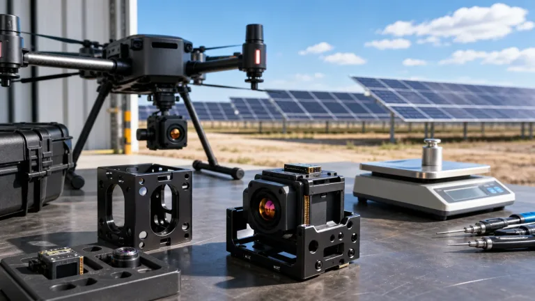
- ✅ Payload Miniaturization: Shrinking the pixel pitch from 17 µm down to 12 µm cuts the total active sensor area by roughly 50% for the same pixel matrix. At the same array format and angular sampling, a shorter focal length and smaller aperture may be possible at a fixed F-number. Actual lens mass, volume and detection range depend on the complete optical design.
- ✅ Instantaneous Field of View (IFOV): The small-angle sampling approximation is IFOV = d / f, where d is the microbolometer pitch and f is the optical focal length. At the same focal length, a 12 µm pitch gives tighter angular sampling than 17 µm; usable stand-off distance also depends on optical contrast, detector noise and the target.
- ✅ Modulation Transfer Function (MTF): Pixel pitch alone does not establish MTF. Check detector and lens MTF together when evaluating edge contrast for object classification or small industrial features.
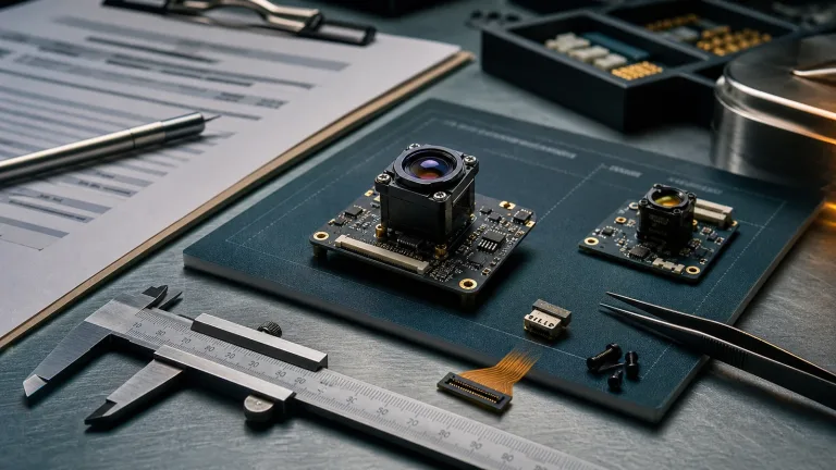
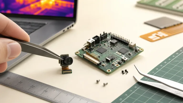
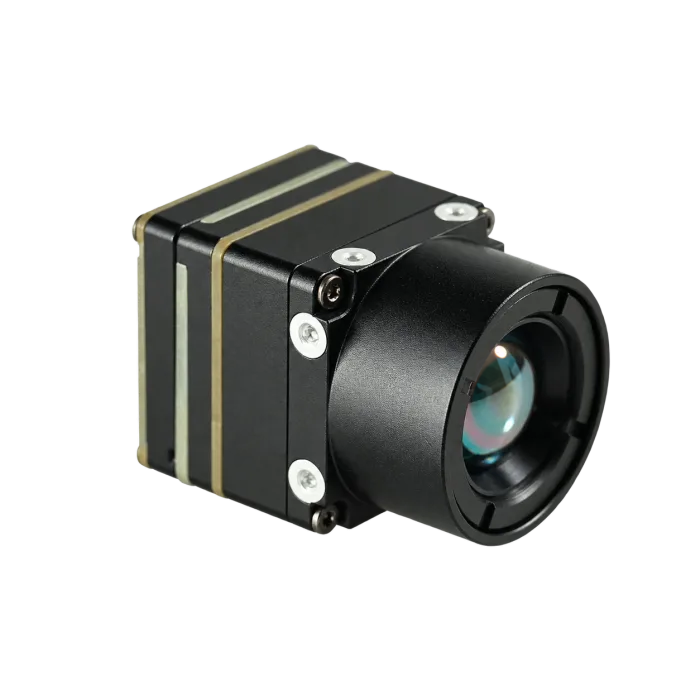
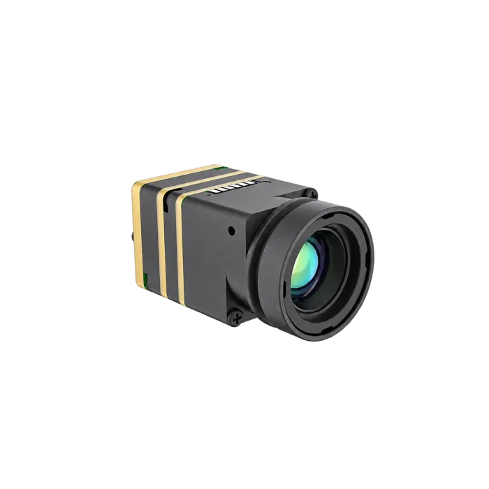
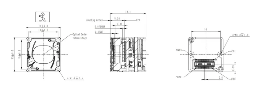
For compact automation rigs or auxiliary monitoring nodes, first define the minimum resolution, mass and power the task needs; a lower-resolution core may be sufficient. A separate 640-class OEM imaging option is CAMCUDA AeroMini 640 in its non-radiometric 9 mm USB + CVBS + MIPI configuration. It uses a 640 × 512, 12 µm VOx detector with a 60 Hz factory default or 30 Hz factory option. It shows relative heat patterns without calibrated temperature readings. Treat it as an integration component: confirm the complete lens-and-board envelope, host interface and power budget before selection.
2. Optical Engineering: Focal Length, Aperture, and DRI Range Modeling
Thermal optical assemblies operate strictly in the infrared spectrum. Standard optical glass is completely opaque to LWIR wavelengths; point an 8–14 µm sensor through standard borosilicate glass and it looks like a solid brick wall. Thermal optics use LWIR-transmitting materials such as Germanium (Ge) or Chalcogenide glass. Specify suitable Anti-Reflective (AR) coatings and, where needed, a protective coating such as Diamond-Like Carbon (DLC) for the operating environment.
Aperture Throughput (F-Number) and Energy Transmission
In thermal optics, the aperture ratio is the F-number (F/# = f / D, where f is focal length and D is the entrance pupil diameter). For the same extended scene and comparable lens transmission, image-plane irradiance (E) approximately follows:
E ∝ 1 / (F/#)2 = D2 / f2
An F1.0 optical design admits more radiation than an F1.2 or F1.4 design under the same scene and transmission assumptions. Relative irradiance falls by about 30.6% and 49.0%, respectively. As an illustrative F-number scaling estimate, a 20 mK system at F1.0 would become about 28.8 mK at F1.2 or 39.2 mK at F1.4 if other factors stayed unchanged. Verify system NETD with the chosen lens; F1.0 is not a universal requirement.
Johnson’s Criteria & Illustrative DRI Sampling
Johnson’s criteria provide a historical framework for detection, recognition and identification estimates. The numbers below are chosen solely to illustrate geometric sampling; they are not Johnson thresholds and do not predict success at any task. A full range model must state target dimensions, contrast, atmosphere, MTF and success probability:
| Illustrative DRI Task | Operational Definition | Assumed Pixels Across Target Height | Equivalent Pixel Pairs (2 Pixels per Pair) |
|---|---|---|---|
| Detection example | Target is present against the thermal background. | 3 pixels | 1.5 pixel pairs |
| Recognition example | Classify target type (human vs. animal vs. vehicle). | 12 pixels | 6 pixel pairs |
| Identification example | Discern specific details (gear worn, vehicle variant). | 24 pixels | 12 pixel pairs |
For the stated sampling assumption, estimate the distance at which a selected target dimension spans the chosen number of pixels. This is a geometric sampling estimate, not a maximum detection-range specification:
Rsample = (Selected Target Dimension × Lens Focal Length) / (Assumed Pixels × Pixel Pitch)
Let’s run the numbers for an illustrative 640×512, 12 µm core with a 70mm lens: a 1.8-meter target height spans 3 pixels at the calculated distance. This is not a specification for the current OEM modules or a guarantee that a person will be detected:
Rsample = (1.8 m × 0.070 m) / (3 × 12 × 10-6 m) = 0.126 / 0.000036 = 3,500 meters
Use the CAMCUDA Thermal Imaging Calculator for IFOV, FOV and scene-coverage planning. Its DRI assumptions use 1.5/6/12 pixels rather than this article’s illustrative 3/12/24, so do not treat its default DRI output as a reproduction of the 3,500 m example or a field-performance guarantee.
3. Digital Video Pipelines, Interfaces, and Machine Vision Standards
Raw electrical data off a microbolometer array is rough. It requires substantial on-sensor processing and calibration before you get usable image streams for an operator display or an AI inference engine. Calibrated temperature data requires a radiometric model and its documented output mode.
The Real-Time Image Processing Pipeline
Modern high-performance thermal cores run dedicated image signal processors (ISPs) to execute complex algorithmic corrections on the fly at the frame rate supported by the selected model and output mode:
- ⚙️ Non-Uniformity Correction (NUC): Due to microscopic semiconductor manufacturing variations, every single microbolometer pixel has its own unique baseline offset and gain slope. The ISP applies calibrated gain and offset corrections; shutter-based or shutterless compensation may reduce drift during operation. Confirm the update behavior and any image interruptions for the selected core.
- ⚙️ Bad Pixel Replacement (BPR): Individual microbolometer pixels can drift or fail over time. Bad-pixel correction can use a stored map or detected defects and substitute values based on neighboring pixels to reduce visible artifacts.
- ⚙️ Dynamic Range Compression & Digital Detail Enhancement (DDE): Some cores process 14-bit or 16-bit samples internally (16,384 or 65,536 code values). Display pipelines often map these values to 8-bit grayscale (256 levels) or color output. DDE and tone mapping can emphasize local contrast and edges, but their settings may also change scene appearance.
Embedded Hardware Interfaces: MIPI, DVP, USB, and Analog
Picking the right electrical interface is critical to avoiding latency bottlenecks and compute overhead on your host processor:
- ⚙️ MIPI-CSI2 & Parallel DVP: These interfaces can carry image data into a compatible host receiver. Confirm lane or bus configuration, pixel format, timing and driver support for the selected core and SoC. Neither interface guarantees RAW14, calibrated temperature data or sub-30 ms glass-to-glass latency. For a full breakdown of pinouts, hardware routing, and signal timing, dig into our technical guide on thermal camera module interfaces (USB, MIPI, CVBS, DVP).
- ⚙️ USB-C and UVC: USB-C is a connector type; UVC is a video protocol that can simplify host integration when supported. Confirm the advertised video modes and whether simultaneous streams are available. Y16 denotes a 16-bit grayscale container, not a guarantee of radiometric temperature data.
- ⚙️ Analog CVBS: CVBS can simplify connections to compatible field monitors, FPV links or legacy CCTV equipment. Common PAL and NTSC modes use 50 and 59.94 fields per second, respectively, rather than a universal 50 full frames per second. Confirm the selected standard and measure end-to-end latency; analog output is not zero-latency.
Industrial Machine Vision and Computer Vision Protocols
When you’re wiring thermal vision into automated factory floors and smart robotics, standard integration protocols are non-negotiable. Compliance with the A3 GigE Vision Standard supports standardized image transport and GenICam feature descriptions. Check IEEE 1588 Precision Time Protocol (PTP) support, triggers, network configuration and measured timing separately; GigE Vision does not by itself guarantee deterministic latency or synchronized capture.
Computer vision models can use processed thermal images or documented high-bit-depth output when available. Match the input format to the trained model and validate defect classification or perimeter tracking with representative data; image bit depth alone does not establish radiometric accuracy or optical gas-imaging capability. You can explore the latest research on infrared target tracking and multi-spectral sensor fusion over at ArXiv Computer Vision.
4. Field Hardware: Handheld & Long-Range Observation Systems
If you’re outfitting mobile inspection crews or setting up fixed perimeter posts, specify the complete optomechanical system, operator workflow and acceptance tests. The table below compares the evidence to request for portable handheld and long-range observation systems. It is a procurement checklist, not a tested product comparison. The separate AeroMini and SuperMini examples in this guide are OEM components that still need host electronics, power, a display, housing and system validation.
| System Parameter | Portable handheld system requirements | Long-range observation system requirements |
|---|---|---|
| Hardware evidence | Request photographs and a complete assembly drawing showing the lens, display, controls, battery and enclosure. | Request system photographs and assembly drawings showing the optics, viewer/display, power pack and tripod or fixed mount. |
| Sensor Technology | Confirm the detector, spectral band and whether the delivered instrument provides imaging or calibrated temperature measurement. | Confirm detector and spectral response against the scene, operating conditions and required observation task. |
| Resolution Options | Choose the pixel matrix from the smallest feature, working distance and scene coverage; validate with a sample. | Specify pixels on the target at the required distance, together with scene coverage and a field acceptance test. |
| Pixel Pitch | Use the actual pitch and focal length to calculate IFOV; pixel pitch alone does not specify image quality. | Calculate angular sampling from the proposed detector and lens; review optical MTF and focus across the field. |
| Frame Rate | Measure the delivered video rate and display latency during normal panning, including NUC interruptions. | Validate tracking at the required target motion and scan rate through the full camera, link and display path. |
| Objective Optics | Specify lens focal length, F-number, focus range and working-distance coverage; verify the quoted optical assembly. | Request the proposed focal length, aperture, transmission and focus control; require evidence for the claimed range. |
| Field of View (FOV) | Confirm horizontal and vertical coverage at the intended working distance. | Balance narrow-field detail with search coverage; verify the actual lens-and-detector FOV. |
| Thermal Sensitivity | Compare NETD at stated scene temperature, F-number and frame rate; specify radiometric accuracy separately if needed. | Request NETD conditions and low-contrast field results; sensitivity alone does not establish fog or range performance. |
| Weight Envelope | Weigh the complete handheld instrument, including lens and battery, and assess one-handed use over a shift. | Budget the complete optics, enclosure, display, battery and support equipment; evaluate balance and mounting loads. |
| Primary Applications | Mobile inspection, field survey and plant diagnostics, with radiometry specified where measured temperatures are required. | Perimeter watch, search and rescue, and long-range patrol, subject to application-specific field validation. |
Deep-Dive: Portable Handheld Inspection Requirements
Field engineers, utility maintenance crews and mobile inspection teams need a complete instrument with a readable display, usable controls, a practical battery workflow and an enclosure suited to the site. If the project is building that instrument, AeroMini 640 is an OEM imaging option to evaluate. The selected non-radiometric 9 mm module does not supply the finished handheld workflow or calibrated temperature measurements.
In the shop, flexibility matters. Match sensor sampling and optical field of view to the smallest feature at a safe working distance, then check focus, contrast and display behavior on representative equipment. For temperature reporting, require a radiometric configuration with stated accuracy and calibration conditions. For a full-shift survey, test total instrument weight, grip balance, gloved controls, display visibility, battery changes and the claimed enclosure protection as a complete assembly.
Technical Verification Priorities:
- ✅ Detector Sampling: Compare candidate resolutions at the same scene coverage and working distance; keep the minimum feature visible in a recorded acceptance image.
- ✅ Sensitivity Evidence: Request NETD test conditions and low-contrast sample imagery; require separate accuracy evidence for temperature measurements.
- ✅ Optical Fit: Confirm focal length, aperture, focus range and whether the lens is fixed or interchangeable in the delivered instrument.
- ✅ Handheld Ergonomics: Evaluate the complete instrument with its lens and battery for one-handed use, screen visibility and sustained operation.
Pre-Procurement RFQ Checklist:
- ⚙️ 1. Specify detector sampling, working distance and whether the task needs imaging or calibrated temperature measurements.
- ⚙️ 2. Select lens and focus requirements from target size, stand-off distance and scene coverage; request a configuration-specific drawing.
- ⚙️ 3. Define battery workflow, mounting accessories, and transport cases.
- ⚙️ 4. Confirm order volume, schedule, destination and compliance requirements; ask which configuration-specific supporting documents are available.
Review AeroMini OEM Configuration ➔
Deep-Dive: Long-Range Observation Requirements
For long-range observation, perimeter watch, coastal monitoring or search and rescue, start with a target definition and field acceptance plan. If the project is developing custom hardware, CAMCUDA SuperMini 640 provides a separate 640 × 512, 8 µm OEM imaging path at 50 Hz. Its compact core does not establish long-range performance; the optical assembly, display, power system, weather protection and mounting remain system-level work.
When you need to identify targets at distance, evaluate focal length, aperture, optical transmission, atmospheric conditions and target contrast together. A narrow field of view trades search coverage for angular detail, so test detection, recognition and identification as separate tasks. For prolonged viewing, assess a single-display or dual-eye arrangement with the actual operators. Measure end-to-end latency during panning, battery endurance and tripod stability; neither a frame-rate label nor a small core guarantees an effective field instrument.
Technical Verification Priorities:
- ✅ Detector Sampling: A 640 × 512 array contains 327,680 pixels; confirm how many pixels cover the target with the proposed lens and distance.
- ✅ Optical Reach: Require lens-specific FOV, aperture, transmission and focus data, followed by representative field results for the stated target and weather.
- ✅ Motion Performance: Test target motion through the sensor, processing, link and display, including dropped frames and correction interruptions.
- ✅ Viewing Ergonomics: Assess single-display and dual-eye options for comfort, eye relief, focus adjustment and total system weight during a representative shift.
Pre-Procurement RFQ Checklist:
- ⚙️ 1. Define target size, detection/recognition/identification task, scene coverage and environmental conditions for the range acceptance test.
- ⚙️ 2. Define primary operational environment (perimeter defense, coastal watch, search and rescue).
- ⚙️ 3. Specify tripod interfaces, battery packs, and field harness requirements.
- ⚙️ 4. Request the exact system datasheet, assembly and interface files, export classification, and any applicable procurement documents; confirm availability and scope.
Review SuperMini OEM Configuration ➔
5. Compliance, Regulatory Verification, and Sourcing Best Practices
Look, procuring advanced thermal imaging hardware isn’t just about reading specs—it requires staying ahead of international export regulations, defense sourcing mandates, and environmental ruggedization standards. Dropping the ball on compliance during early procurement will cost you months in customs delays or run your project straight into legal liability.
Export Controls: Frame Rate Restrictions and Dual-Use Regulations
Thermal-camera export requirements depend on the applicable jurisdiction, item classification, technical configuration, destination, end-user and end-use. For transactions subject to U.S. controls, determine whether EAR or ITAR applies rather than inferring it from frame rate alone:
- ⚙️ 9 Hz vs. 50 Hz/60 Hz Frame Rates: A rate of 9 Hz or less may affect classification, but it is not a blanket export exemption; end-user and end-use restrictions can still apply. Higher frame rates can improve motion sampling, but 50 Hz or 60 Hz alone does not determine licensing. Obtain the classification and any required authorization or end-user documentation for the actual shipment.
- ⚙️ Spatial Resolution and Configuration: Array size, detector type, optics and other characteristics can affect export classification. Do not use 640×512 resolution or a sub-20 mK NETD as a stand-alone legal threshold. Request a configuration-specific classification and verify destination and end-use requirements.
NDAA Section 889 Compliance & Sourcing Documentation
For applicable U.S. federal procurement, NDAA Section 889 and the implementing FAR provisions restrict covered telecommunications and video-surveillance equipment and certain contractor use, subject to defined exceptions or waivers. Review the covered entities, equipment, representations and contract requirements; a generic “NDAA compliant” label is not sufficient evidence. For step-by-step documentation templates and verification guidelines, check out our engineering briefing on NDAA thermal camera module North America RFQ documents.
Environmental Validation and Reliability Testing
To survive real-world field conditions, specify relevant environmental tests and obtain reports for the finished hardware configuration:
- ⚙️ Ingress Protection (IP Rating): Specify enclosure protection for the exposure: IP66 covers powerful water jets, while IP67 covers temporary immersion under defined test conditions; both include dust-tight protection. One water rating does not automatically establish the other. Request the applicable test report for the assembled unit.
- ⚙️ Thermal Shock & Operating Envelopes: Specify the required operating and storage temperatures, thermal cycling and image-stability criteria. Confirm the selected assembly’s published limits and test performance across the intended range; imaging operation and temperature-measurement accuracy may have different limits.
- ⚙️ Optical Hardening: For exposed optics, request coating durability and transmission data relevant to sand, salt fog and cleaning. DLC is one protective option; coating choice and qualification depend on the lens and environment.

Technical author: Daniel · Hardware Support; Sales contributors: Vivian, Lena and Sophie.
6. Engineering FAQ & Technical Diagnostics
What should buyers verify in thermal cameras under $400 for industrial and field use?
What specific parameters define the best thermal camera for long-range field observation?
How can engineering teams achieve real-time thermal video streaming on embedded SBCs like Raspberry Pi and NVIDIA Jetson?
How should an engineering team choose between 384×288 and 640×512 thermal resolutions?
📚 References & Further Reading
- Industry Standard: A3 GigE Vision Standard – Automated Imaging Association protocol for high-performance machine vision streaming.
- Computer Vision Research: ArXiv Computer Vision – Recent academic research on infrared object tracking, super-resolution, and multi-modal AI processing.
- Related Sourcing Guide: NDAA Thermal Camera Module North America RFQ Documents – Sourcing and compliance guidelines for federal and industrial integrators.
- Hardware Interface Guide: Thermal Camera Module Interfaces (USB, MIPI, CVBS, DVP) – Technical analysis of embedded video bus topologies and signal timing.
- OEM Documentation: AeroMini 640 – datasheet, configuration FAQ and developer resources. For the separate SuperMini core, use the SuperMini 640 / 640T product manual. Review the CAMCUDA FAQ before sending a configuration-specific RFQ.