OEM UAV Camera for Sale: Guide to EO, Thermal & AI Tracking Payloads
OEM UAV Camera for Sale: Engineering Guide to EO, Thermal & AI Tracking Payloads
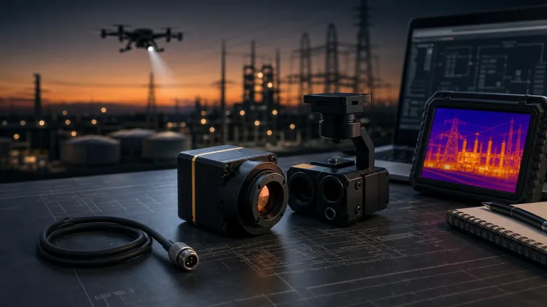
Selecting an industrial-grade uav camera for sale requires navigating real-world engineering trade-offs between optical resolving power, thermal sensitivity, onboard neural computing throughput, and uncompromising Size, Weight, Power, and Cost (SWaP-C) constraints. If you have spent any time bench-testing airframes in the shop, you know modern unmanned aerial systems (UAS) operating across tactical reconnaissance, perimeter security, critical infrastructure inspection, border surveillance, and search-and-rescue (SAR) missions can no longer lean on laggy analog downlinks or bulky companion computers bolted to the belly of an aircraft. State-of-the-art vision payloads demand tightly coupled architectures that combine high-frame-rate Electro-Optical (EO) CMOS sensors, Long-Wave Infrared (LWIR) thermal microbolometers, and dedicated hardware Neural Processing Units (NPUs) into a single, cohesive processing stack.
When sizing up an embedded uav camera for sale, looking strictly at megapixel counts or lens focal lengths will lead you down the wrong path. What actually makes or breaks an aerial system in the field comes down to deterministic edge-inference latency, hardware-level flight-controller communication protocols (like native CRSF and MAVLink), minimum target lock thresholds, and tracking loop stability when the airframe pulls high-G maneuvers. This engineering guide breaks down the underlying physics and architectures of modern EO and thermal drone vision systems, tears into embedded edge-AI tracking engines, details mission-critical avionics integration protocols, and provides full technical parameters for field-proven embedded AI tracking payloads.
Table of Contents
- 👉 1. Core Payload Architectures: Visible (EO), LWIR Thermal, and Dual-Spectrum Systems
- 👉 2. Edge-AI Integration & Onboard Target Tracking Mechanics
- 👉 3. SWaP-C Optimization & Flight Controller Avionics Integration
- 👉 4. Featured OEM UAV Camera Modules & Technical Specifications
- 👉 5. Avionics Integration, EMI/EMC Decoupling, and Flight Testing Protocols
- 👉 6. OEM Procurement & RFQ Evaluation Checklist
- 👉 7. Frequently Asked Engineering Questions (FAQ)
1. Core Payload Architectures: Visible (EO), LWIR Thermal, and Dual-Spectrum Systems
Here’s the deal: unmanned payload imaging systems break down into three primary sensor categories: Visible/Electro-Optical (EO), Long-Wave Infrared (LWIR) Thermal, and Hybrid Dual-Spectrum systems. Sourcing the right system comes down to matching fundamental sensor physics to your flight envelope, ambient lighting, and tracking requirements.
1.1 Electro-Optical (EO) Visible Sensor Physics
Visible EO camera payloads collect reflected electromagnetic energy in the visible band (roughly 400 nm to 700 nm). For aerial surveillance, high-speed mapping, and dynamic tracking, the physical sensor format and low-light signal-to-noise ratio (SNR) dictate real-world performance:
- ⚙️ Sensor Format & Pixel Pitch: Industrial 1/1.8-inch CMOS formats strike the sweet spot between physical module footprint and individual photodiode collection area. Larger pixel wells capture more photons per integration period, giving you usable target discrimination down to 0.001 lux without choking the feed with luminance noise.
- ⚙️ High Frame Rate Video Feeds: Standard 30 Hz commercial camera feeds suffer from bad motion blur and temporal aliasing the second an aircraft banks hard. Tactical EO payloads push 60 Hz to 120 Hz raw sensor output, giving tracking algorithms clean temporal data for tight frame-by-frame feature matching.
- ⚙️ Optical Field of View (FOV): Lens selection is always a balancing act between situational awareness and standoff distance. A wide lens (e.g., $109^\circ$ H-FOV at $f=4.37\text{ mm}$) delivers wide scene coverage for low-altitude close-quarters flight, while narrower glass (e.g., $57.1^\circ$ H-FOV at $f=8.45\text{ mm}$) packs pixels onto distant vehicles and personnel.
1.2 Long-Wave Infrared (LWIR) Thermal Microbolometers
Unlike visible imagers that depend on reflected ambient light, LWIR microbolometers register blackbody radiation emitted directly by objects across the 8 µm to 14 µm atmospheric transmission window. That makes LWIR thermal cores fully daylight-independent, cutting straight through total darkness, light smoke, dust, and marine haze.
Modern thermal cores run uncooled Vanadium Oxide (VOx) focal plane arrays. VOx easily outperforms legacy amorphous Silicon ($\alpha\text{-Si}$) in thermal stability and delivers a substantially lower Noise Equivalent Temperature Difference (NETD). With a tight 12 µm pixel pitch and native $640 \times 512$ resolution running at 50 Hz, uncooled VOx cores allow engineers to deploy ultra-compact optics ($f=9.1\text{ mm}$) that deliver crisp thermal contrast curves for automated target extraction. To ensure optimal hardware decoupling and sensor isolation, engineers should review the technical guidelines outlined in the IR Camera Module Drone OEM Integration Checks.
1.3 Dual-Spectrum Fusion and Hardware Picture-in-Picture (PIP)
Relying on a single sensor forces operational compromises every time: EO cameras go blind in zero-lux or heavy haze, while thermal imagers lack fine surface textures, paint markings, and optical color data. Dual-spectrum UAV camera payloads bridge that operational gap by mounting a high-definition visible CMOS sensor and an uncooled LWIR microbolometer onto a shared compute backplane.
Look, with hardware-accelerated processing onboard, dual-channel payloads output real-time Picture-in-Picture (PIP) overlays, side-by-side feeds, and instant spectral switching on command. An integrated edge AI processor can lock onto a thermal hot spot and cross-reference high-res visible imagery to verify target classification on the fly. Integrators seeking detailed operational architectures should consult the dedicated analysis on Drone Thermal Camera Applications.
2. Edge-AI Integration & Onboard Target Tracking Mechanics
Traditional aerial surveillance architectures routed analog or digital video over an RF datalink down to a Ground Control Station (GCS). The ground computer ran the tracking software and radioed steering corrections back up to the drone. In practice, that round-trip loop creates 150 ms to 350 ms of lag, dropped frames, and control stutter—making stable tracking of fast-moving targets impossible the moment RF interference kicks in.
Modern embedded camera payloads wipe out that bottleneck by running hardware Neural Processing Units (NPUs) directly inside the camera stack itself. This creates an air-gapped, zero-RF-dependent control loop with tracking latencies dropping to between 8 ms and 30 ms.
2.1 Embedded Neural Processing Units (4 TOPS to 6 TOPS)
Current onboard AI vision engines pack multi-core neural processors delivering between 4 and 6 INT8 TOPS of edge inference throughput, backed by multi-core CPU clusters (like Arm Cortex-A76 and Cortex-A55). This compute density lets the camera run heavy convolutional neural networks (CNNs) and transformer models right on uncompressed, raw MIPI-CSI2 frames before anything gets encoded or transmitted.
- ✅ Pixel-Level Target Discrimination: Onboard neural networks spot and classify people, vehicles, marine vessels, and structural points inside bounding boxes as tiny as $10 \times 10$ pixels.
- ✅ Multitarget Kinematic Tracking: Edge tracking pipelines assign unique IDs and manage state estimation for 60 to 120 dynamic targets across the frame simultaneously.
- ✅ Direct Error Vector Computation: Instead of piping heavy video to an external processor, the edge AI calculates target deviation vectors ($\Delta X, \Delta Y$) directly and feeds lightweight correction telemetry straight into the flight controller’s navigation loop.
For a broader conceptual understanding of machine learning algorithms applied to autonomous edge systems, refer to the foundational overview of Artificial Intelligence on Wikipedia.
2.2 Autonomous Tracking Modes and Dynamic Profiles
An industrial tracking payload has to hold lock through physical occlusions, perspective warps, and rapid yaw changes. Modern embedded AI cameras use several proven tracking algorithms:
- ⚙️ Reticle Locking & Close-to-Lock: The operator flags a target using ground telemetry or an RC toggle; the onboard model locks onto target spatial features and stabilizes the optical axis around the target centroid.
- ⚙️ Lost-Target Recall & Kinematic Extrapolation: When a tracked vehicle dips under tree cover, a bridge, or building shadow, an embedded Kalman filter projects velocity and trajectory vectors, holding the tracking point until the target re-emerges.
- ⚙️ High-Speed Dynamic Intercept: High-end 6 TOPS dual-spectrum engines track targets closing or moving at relative speeds up to 450 km/h, making them ideal for high-speed interceptors, fixed-wing platforms, and rapid-response VTOL drones.
- ⚙️ Route Pre-Mapping & Tripwire Surveillance: The AI engine continuously monitors user-defined coordinate corridors, automatically initiating active tracking when an unauthorized person or vehicle breaches the virtual boundary.
3. SWaP-C Optimization & Flight Controller Avionics Integration
Every gram of payload and every milliwatt of wasted power cuts into your airframe’s flight endurance, battery health, and operational radius. Squeezing maximum SWaP-C efficiency out of your build requires tight electrical and physical integration between the vision sensor and the flight avionics bus.
3.1 Direct Flight Controller Communication via CRSF and Serial Protocols
Forget the days of running bulky companion single-board computers, external protocol converter boards, and messy USB harnesses. Modern embedded AI cameras talk directly to flight controllers running BetaFlight, ArduPilot, or PX4 using standard CRSF (Crossfire) or serial MAVLink protocols.
Hooking the camera module straight up to a flight controller UART over CRSF at high baud rates integrates the payload directly into the RC architecture. That direct bus link gives the pilot or autonomous ground station full control to:
- ✅ Switch between EO, Thermal, and PIP views instantly via RC transmitter aux channels.
- ✅ Trigger active target locks, center the reticle, or fire lost-target recall right from the radio.
- ✅ Feed real-time tracking error telemetry straight into autopilot autonomous flight modes (like “Follow-Me”, “Orbit”, or “Visual Servoing”) with zero ground-loop latency.
3.2 Power Supply Conditioning and Thermal Management
Crunching 4 to 6 TOPS of neural compute inside tiny $38 \times 38\text{ mm}$ or $45 \times 45\text{ mm}$ enclosures generates real heat. Keeping your hardware alive requires clean electrical and thermal planning:
- ⚙️ Regulated DC Power Rail: Always power the camera modules from a clean, regulated 9–16 V DC rail. Never wire processing boards straight to main battery leads—inductive voltage spikes generated by motor ESC active braking will fry sensitive edge processors.
- ⚙️ Thermal Dissipation Paths: Make sure the module stack is mechanically coupled to aluminum standoffs or mounted directly in the airframe’s propwash to keep silicon temperatures well below maximum junction limits during hot-weather flights.
4. Featured OEM UAV Camera Modules & Technical Specifications
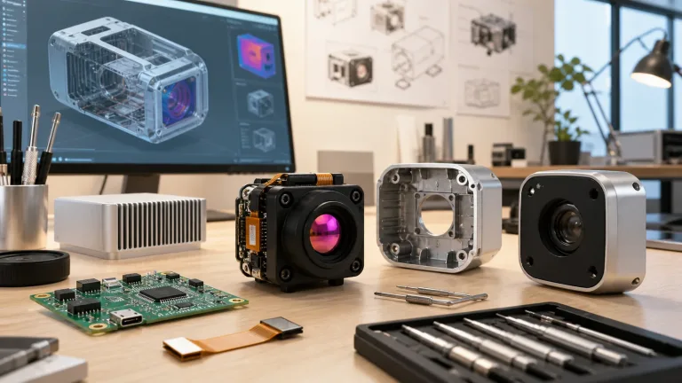
For systems integrators, drone manufacturers, and defense OEMs evaluating an OEM uav camera for sale, the following embedded tracking platforms deliver industry-leading performance across visible and dual-spectrum operational profiles.
TC01-HD 4 TOPS UAV AI Tracking Module with HD Camera
Ultra-Compact Wide-Angle EO Intelligence for Lightweight UAV & Robotics OEMs
The TC01-HD combines an ultra-compact 4 TOPS edge-AI processing stack ($38 \times 38 \times 24.5\text{ mm}$) with a wide-angle 1/1.8-inch visible CMOS camera designed specifically for compact UAV prototypes, micro-reconnaissance drones, and mobile robotics where mounting space and weight budgets are critically constrained. Delivering $2160 \times 1440$ resolution at 60 Hz, the TC01-HD executes onboard person and vehicle detection, dynamic tracking, Picture-in-Picture (PIP) rendering, and seamless CRSF flight-controller telemetry integration.
TC01-HD Technical Parameter Specifications:
| Category | Engineering Parameter | Specification Value |
|---|---|---|
| AI & Tracking Engine | Target Classification | Person and Vehicle |
| Detection Range Reference | Vehicle: 800 m; Person: 300 m (Scene-dependent reference) | |
| Minimum Target Size | $10 \times 10$ pixels | |
| Processing Latency | 30 ms reference | |
| Dynamic Tracking Speed | Up to 140 km/h | |
| Maximum Concurrent Targets | Up to 60 identified targets | |
| Display Modes | PIP (Picture-in-Picture) supported | |
| Compute & Avionics | Edge AI Processing Power | 4 TOPS Dedicated NPU |
| Control Protocol | CRSF (Crossfire Protocol) | |
| Flight Controller Compatibility | BetaFlight and ArduPilot | |
| Input Operating Voltage | 9 – 16 V DC (Regulated input required) | |
| Processing Board Size | $38 \times 38 \times 24.5\text{ mm}$ | |
| Mechanical Mounting Pattern | $25.5 \times 25.5\text{ mm}$ | |
| EO Optical Sensor | Image Sensor Format | 1/1.8-inch CMOS |
| Focal Length | $4.37\text{ mm}$ | |
| Optical Field of View (FOV) | Diagonal: $131.6^\circ$ / Horizontal: $109^\circ$ / Vertical: $57.5^\circ$ | |
| Minimum Illumination | 0.001 lux reference | |
| Sensor Resolution & Frame Rate | $2160 \times 1440$ @ 60 Hz | |
| Camera Head Dimensions | $25.5 \times 19.5 \times 19.5\text{ mm}$ |
Supply Boundary Notice: CAMCUDA supplies the TC01-HD module configuration only. Airframe, flight controller, RC receiver, ESCs, motors, datalink transmitter, ground station software, and enclosures are not included unless explicitly quoted.
TM02-SOLO T 6 TOPS UAV AI Tracking Module with 640 Thermal Camera
High-Speed Dual-Spectrum (EO + 640 LWIR) Multi-Core Tracking Powerhouse
The TM02-SOLO T represents the pinnacle of multi-spectrum aerial intelligence, combining an Arm Cortex-A76 ($2.4\text{ GHz}$) plus Cortex-A55 ($1.8\text{ GHz}$) hybrid processor delivering 6 TOPS of dedicated edge-AI compute with both a high-frame-rate 1080p @ 120 Hz EO camera and an uncooled $640 \times 512$ @ 50 Hz VOx thermal camera. Engineered for tactical defense, high-speed perimeter intercept, and all-weather search and rescue, the TM02-SOLO T performs multi-target identification and dynamic tracking up to a blazing 450 km/h relative velocity.
TM02-SOLO T Technical Parameter Specifications:
| Category | Engineering Parameter | Specification Value |
|---|---|---|
| AI & Tracking Engine | Target Classification | Person and Vehicle (Visible & Thermal Contrast) |
| Detection Range Reference | Vehicle: 400 m; Person: 170 m | |
| Minimum Target Size | $10 \times 10$ pixels | |
| Processing Latency | 8 ms supplier table reference (Sub-30 ms end-to-end) | |
| Dynamic Tracking Speed | Up to 450 km/h | |
| Advanced Tracking Modes | Reticle locking, close-to-lock, route pre-map, lost-target recall, PIP | |
| Maximum Concurrent Tracks | Up to 120 dynamic target tracks (firmware dependent) | |
| Compute & Avionics | Edge AI Compute Power | 6 TOPS Dedicated INT8 NPU |
| Main CPU Architecture | Arm Cortex-A76 @ 2.4 GHz + Cortex-A55 @ 1.8 GHz | |
| Control Protocol | CRSF (Crossfire Protocol) | |
| Flight Controller Support | BetaFlight and ArduPilot | |
| Input Operating Voltage | 9 – 16 V DC Regulated | |
| Processing Board Size | $45 \times 45 \times 26\text{ mm}$ | |
| Mechanical Mounting Pattern | $42.5 \times 42.5\text{ mm}$ | |
| Visible (EO) Channel | Sensor Format | 1/1.8-inch High Dynamic Range CMOS |
| Focal Length | $8.45\text{ mm}$ | |
| EO Field of View (FOV) | Diagonal: $66.3^\circ$ / Horizontal: $57.1^\circ$ / Vertical: $30.4^\circ$ | |
| Minimum Illumination | 0.001 lux reference | |
| Resolution & Frame Rate | $1920 \times 1080$ @ 120 Hz | |
| Camera Head Dimensions | $25.5 \times 19.5 \times 19.5\text{ mm}$ | |
| Thermal (LWIR) Channel | Thermal Detector Type | Uncooled Vanadium Oxide (VOx) Microbolometer |
| Spectral Range | 8 – 14 µm (Long-Wave Infrared) | |
| Pixel Pitch | 12 µm | |
| Thermal Focal Length | $9.1\text{ mm}$ | |
| Thermal Field of View (FOV) | Diagonal: $61.8^\circ$ / Horizontal: $47.7^\circ$ / Vertical: $38.2^\circ$ | |
| Resolution & Frame Rate | $640 \times 512$ @ 50 Hz | |
| Board Connection Protocol | High-Speed Direct MIPI Interface |
Radiometric Notice: The TM02-SOLO T thermal channel is engineered for imaging contrast and dynamic AI target tracking. Current documentation does not specify factory-calibrated absolute radiometric temperature measurement; select alternative calibrated sensors if absolute thermal metrology is required.
For broad architectural benchmarks regarding IP video transmission, low-light image processing, and industrial surveillance standards, explore the enterprise vision solutions developed by Axis Communications.
5. Avionics Integration, EMI/EMC Decoupling, and Flight Testing Protocols
Look, putting an AI vision module into an operational airframe isn’t just about plugging in connectors. You’re cramming high-frequency edge NPUs and digital CMOS sensors right next to sensitive GPS antennas, telemetry transceivers, and noisy brushless motors. If you don’t handle EMI and vibration up front, you will run into headaches during flight testing.
5.1 Electromagnetic Interference (EMI) Mitigation
High-speed MIPI-CSI2 lines running between the optical head and the NPU board, along with onboard DC-DC switching regulators, pump out RF hash. Left unshielded, they will raise the noise floor on your GNSS receiver at 1.5 GHz or degrade range on 433 MHz, 868 MHz, 915 MHz, and 2.4 GHz telemetry links.
- ⚙️ Conductive Enclosures & Shielding: Enclose the processing stack inside CNC aluminum housings or wrap flexible MIPI cables with grounded copper foil tape.
- ⚙️ Ground Planes & Filtering: Tie everything back to a clean star ground. Place high-frequency ferrite beads and low-ESR ceramic bypass capacitors on the 9–16 V DC power leads to choke off switching noise coming off the ESCs.
- ⚙️ Spatial Separation: Maintain at least 75 mm of physical clearance between the AI board and onboard GPS patch antennas or sensitive digital compasses.
5.2 Mechanical Vibration and Jitter Decoupling
High-frequency airframe vibrations (typically 100 Hz to 800 Hz) caused by motor imbalance and prop harmonics will induce rolling-shutter “jello” artifacts on CMOS sensors and disrupt microbolometer thermal stability:
- ⚙️ Mount the optical camera heads using tuned silicone or fluorosilicone vibration dampers matched to the exact payload mass.
- ⚙️ Align the camera lens optical axis directly with the payload damping plane to eliminate rotational torque moments during aggressive flight maneuvers.
5.3 Step-by-Step Flight Readiness Verification Protocol
- ⚙️ Step 1: Benchtop Power & Current Verification: Power the payload with a clean bench power supply. Measure baseline idle and peak current draw under full NPU inference and video streaming.
- ⚙️ Step 2: UART & CRSF Channel Mapping: Hook up serial communication with your flight controller software (ArduPilot or BetaFlight). Verify that RC transmitter switches correctly toggle display modes (EO/Thermal/PIP) and trigger target locks.
- ⚙️ Step 3: EMI / RF Noise Floor Sweep: Power up the camera stack and monitor your flight controller’s GPS satellite SNR and telemetry Packet Error Rate (PER). Confirm zero noise-floor elevation across your working RF bands.
- ⚙️ Step 4: Captive Flight Dynamics Check: Perform a tethered or low-altitude hover test. Confirm that motor vibration does not cause image jitter, tracking drops, or optical distortion.
- ⚙️ Step 5: Dynamic Target Engagement Flight: Fly structured test passes against moving ground vehicles at speed across varied operational slant ranges to validate target reacquisition and lost-target recall under real-world conditions.
6. OEM Procurement & RFQ Evaluation Checklist
When you’re ready to put together a formal Request for Quotation (RFQ) for an OEM uav camera for sale, avoid generic specs. Laying out clear hardware boundaries upfront ensures plug-and-play integration and eliminates back-and-forth revision delays.
Technical RFQ Checklist:
- ⚙️ Airframe Envelope & Mass Limits: Provide exact payload bay dimensions ($X \times Y \times Z\text{ mm}$), max payload mass budget (g), and mounting standoff pattern ($25.5\text{ mm}$ vs $42.5\text{ mm}$).
- ⚙️ Power Supply Specification: Detail your regulated DC rail voltage range ($9 – 16\text{ V DC}$), continuous current budget, and BEC ripple suppression rating.
- ⚙️ Optical & Sensor Configuration: State your FOV requirements (wide-angle vs telephoto), sensor requirements (EO-only vs EO/LWIR dual-spectrum), and minimum target detection size ($10 \times 10\text{ pixels}$).
- ⚙️ Autopilot Hardware & Firmware: Specify flight controller hardware, autopilot codebase (ArduPilot Copter/Plane/VTOL vs BetaFlight), and available hardware UART ports for CRSF wiring.
- ⚙️ Operational Scene Profiles: Define target closure speeds (140 km/h vs 450 km/h), maximum working distances (e.g., 800 m vehicle detection), and day/night environmental expectations.
- ⚙️ Commercial Batch Volumes: Outline prototype evaluation quantities, scheduled production batch sizes, delivery schedules, and warranty expectations covered under the standard CAMCUDA Refund Policy.
7. Frequently Asked Engineering Questions (FAQ)
How does CRSF protocol integration streamline tracking control on modern UAVs?
📚 References & Further Reading
- Industry Standard: Axis Communications – Network Video, Edge Processing, and Optical System Standards
- Academic Reference: Wikipedia – Artificial Intelligence – Comprehensive Foundations of Neural Networks and Computer Vision
- Related Integration Guide: CAMCUDA – IR Camera Module Drone OEM Integration Checks
- Application Analysis: CAMCUDA – Tactical & Industrial Drone Thermal Camera Applications
- Commercial Terms: CAMCUDA – Official Warranty, Return & Refund Policy