Infrared Drone Payload Integration: OEM Thermal Camera Core Selection Guide
Infrared Drone Payload Integration: OEM Thermal Camera Core Selection Guide
Integrating a long-wave infrared (LWIR) payload into an unmanned aerial system (UAS) requires balancing optical performance, structural dynamics, thermal management, and embedded computing. An effective infrared drone payload starts with measurable requirements for size, weight, power, and cost (SWaP-C), native spatial resolution, thermal sensitivity, and end-to-end latency. Match the selected module and lens to those requirements, then validate the complete assembly and obtain the documentation needed for procurement.
Review the mechanical envelope, lens mass and mounting, optical coatings, electrical limits, and documented video formats. These affect packaging and qualification, but none alone predicts flight endurance, gimbal stability, or companion-computer performance. Test the full payload, including its enclosure, interface boards, cables, and processing load.
For substation inspection, search and rescue, agricultural surveys, and other civil observation tasks, OEM cores offer flexibility when an engineering team needs a custom payload. Finished camera pods remain another option. A core must match the actual host interface and software stack; naming a Jetson or Raspberry Pi board, or a MAVLink-based aircraft, does not establish compatibility. This guide covers detector selection, optics, gimbal mechanics, video and control paths, environmental qualification, and procurement documents.
A native 1280 × 1024 detector requirement remains a separate selection gate throughout this guide. The current AeroMini 640 example is a 640 × 512, non-radiometric evaluation path only for applications that accept that resolution; it is not a substitute for native 1280 × 1024 capture or calibrated temperature measurement.
Technical author: Daniel · Hardware Support
Sales contributors: Vivian, Lena and Sophie
Table of Contents
- 👉 1. LWIR Detector Physics: VOx Cores, Pixel Pitch, and Thermal Sensitivity (NETD)
- 👉 2. SWaP-C Optimization and Gimbal Dynamics in Aerial Payloads
- 👉 3. Germanium Optics, F-Number Matching, and Johnson’s Criteria Calculation
- 👉 4. Digital Video Pipelines, Latency, and Companion Computer Interfacing
- 👉 5. OEM Thermal Core vs. Ground Inspection Instruments: Specifications Analysis
- 👉 6. Electromagnetic Interference (EMI), Heat Dissipation, and Airborne Enclosures
- 👉 7. Frame Rates, Export Review, and Procurement Documentation
- 👉 8. Frequently Asked Questions (FAQ) for Payload Integrators
1. LWIR Detector Physics: VOx Cores, Pixel Pitch, and Thermal Sensitivity (NETD)
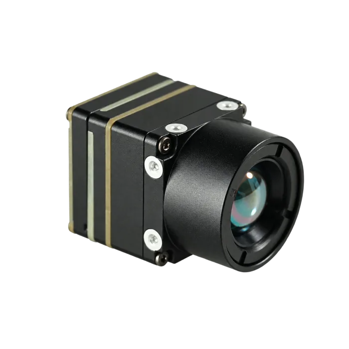
Uncooled microbolometer focal plane arrays (FPAs) are widely used in compact LWIR payloads because they avoid a cryogenic cooling assembly. Cooled infrared detectors remain suitable for some applications with different sensitivity, spectral, or imaging-speed requirements. Compare the complete camera’s mass, power, startup behavior, lifetime, and cost.
The LWIR atmospheric window supports passive imaging without visible illumination, but atmospheric transmission still varies with wavelength, humidity, weather, and path length. In a microbolometer, absorbed infrared radiation changes a thermally isolated sensing element’s temperature and resistance. Readout and processing electronics convert that response into image data. The output may be raw, corrected, display-oriented, or calibrated radiometric data; a 14-bit or 16-bit container alone does not establish temperature units or the order of correction stages.
Vanadium Oxide (VOx) vs. Amorphous Silicon (a-Si)
Vanadium oxide (VOx) and amorphous silicon (a-Si) are established thermistor material families. Their implementations evolve, so select the finished detector and camera against measured requirements rather than treating the film name as a complete performance specification:
- ⚙️ Temperature Coefficient of Resistance (TCR): TCR contributes to responsivity, but its value and the resulting signal-to-noise ratio depend on the material formulation, pixel design, bias, and readout. Request data for the actual detector.
- ⚙️ Noise: Compare NETD under matched optical, temperature, frame-rate, and processing conditions. A material label does not specify the complete camera’s noise behavior.
- ⚙️ Thermal Stability: Evaluate drift and correction behavior through the intended enclosure-temperature changes and airflow conditions. Packaging, calibration, and thermal design matter alongside the sensing material.
- ⚙️ Compare Implementations: Do not reject an a-Si camera solely on its material or assume it is cheaper, less stable, or unsuitable for aerial imaging. Use model-specific image quality, reliability, and integration evidence.
Pixel Pitch Dynamics: 12 µm vs. 17 µm
For the same native array size, reducing pixel pitch reduces the active sensor dimensions. A hypothetical native 1280×1024 array at 12 µm pitch measures 15.36 × 12.288 mm, with a diagonal of about 19.67 mm; at 17 µm, its diagonal is about 27.87 mm.
At the same array count and field of view, a smaller pitch permits a shorter focal length. At the same f-number, this also reduces the required entrance-pupil diameter. Actual lens diameter, mass, image quality, and payload balance depend on the optical prescription, housing, coatings, and mounting. A smaller pitch does not guarantee a lighter assembled payload. A 640×512 array at the same pitch has half the active width and height of 1280×1024, so it has a different field of view with the same lens.
Noise Equivalent Temperature Difference (NETD)
Noise Equivalent Temperature Difference (NETD) describes thermal sensitivity: the scene-temperature difference corresponding to the measured noise under specified test conditions. Compare values only alongside the stated f-number, scene temperature, frame rate, and processing. NETD is separate from absolute temperature-measurement accuracy, spatial resolution, and detection range:
- ⚙️ A stated NETD of ≤ 35 mK: Treat this as a model-specific sensitivity claim under its published conditions, not a universal requirement for 1280×1024 arrays or a guarantee of inspection performance.
- ⚙️ A stated NETD of ≤ 20 mK: A lower matched-condition value may help reveal small thermal contrasts. It does not mean temperature readings are accurate to 0.02°C; radiometric capability, calibration, emissivity, reflections, and target size must be evaluated separately.
Non-Uniformity Correction (NUC) and Thermal Drift Mitigation
Changes in camera and enclosure temperature can affect offset, gain, and image uniformity. Fixed-pattern artifacts can also arise from other causes, so record operating conditions and follow the supplier’s diagnostic procedure rather than attributing every band or vignette to thermal drift.
Non-uniformity correction (NUC) compensates for pixel-response differences. Depending on the design, a camera may use stored calibration tables, shutter-based flat-field correction, temperature compensation, or shutterless methods. Request the selected model’s startup and correction behavior, image interruption duration, triggering rules, and available control/status commands.
2. SWaP-C Optimization and Gimbal Dynamics in Aerial Payloads
Size, weight, power, and cost set practical limits for an airborne payload. For a civil inspection gimbal containing thermal and visible cameras and any processing electronics, budget the complete moving assembly. Lens, mounts, interface boards, enclosure, cabling, and cooling provisions all affect motor selection, stiffness, balance, and power consumption.
If the mission requires native 1280 × 1024 capture, request configuration-specific detector documentation and sample files that establish the native array, delivered frame dimensions, bit depth and processing path. A 1280-wide display, resized encoder stream or upscaled 640 × 512 image does not establish a native 1280 detector. Confirm separately whether calibrated temperature data or RAW/minimally processed output is mandatory.
Keep the optical and mechanical checks attached to that same native-1280 configuration: obtain the selected lens focal length, F-number and horizontal/vertical field of view, then a complete lens-plus-board drawing, installed mass and mounting information. Do not approve a lower-resolution core merely because it fits the gimbal. If 1280 × 1024 is mandatory, the AeroMini 640 example below fails that resolution gate and a compliant configuration still needs to be sourced and verified.
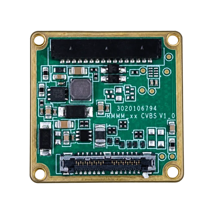
AeroMini USB + CVBS + MIPI interface board, photographed separately from the camera. Match the supplied board revision to its wiring guide; this is not the full lens-and-board assembly.
CAMCUDA AeroMini 640: a 640 × 512 OEM evaluation example
For applications that accept 640 × 512 imaging, evaluate the AeroMini 640 with a 9 mm lens and USB + CVBS + MIPI board. The selected non-radiometric version has a 60 Hz factory default or 30 Hz factory option and shows relative heat patterns without calibrated temperature readings. This configuration does not meet a native 1280 × 1024 requirement; validate image quality, host integration and the complete installed assembly before selecting it for a payload.
- Resolution & Pitch: 640 × 512 uncooled VOx detector, 12 µm pixel pitch; not native 1280 × 1024.
- Thermal Sensitivity: NETD ≤ 30 mK at 25 °C, F/1.0; this sensitivity figure is not a temperature-accuracy specification.
- Camera Version & Rate: Non-radiometric imaging: 60 Hz factory default or 30 Hz factory option. Confirm the delivered rate and each active output.
- Spectral Range: 8–14 µm LWIR.
- Power Input & Budget: The illustrated POWER_IN1 and POWER_IN2 inputs are 5 V. Published typical module consumption is <0.5 W at 25 °C; budget the full kit and host separately.
- Module Size & Mass: 21 × 21 × 28 mm and <20 g, excluding lens and flange. Obtain the complete selected lens/board envelope and installed mass.
- Video Output Paths: USB and MIPI digital paths plus analog CVBS on the selected board. Confirm format, host, firmware and simultaneous-output limits; Type-C + CVBS is a separate package.
- Control Communication: Illustrated 16-pin reference: RS232 RX/TX; 26-pin reference: 3.3 V UART TX/RX. Match board, electrical levels, transceiver, signal direction and command protocol.
- Selected Optics: 9 mm lens, published field of view 48.7° H × 38.6° V. Other lenses require their own configuration and mechanical review.
Weight, Rotational Inertia, and Center of Gravity (CoG)
A bare-core mass or housing dimension is only a starting point for gimbal sizing. Determine the mass distribution of the complete payload about each rotation axis. The simple relation below applies to a point mass at radius r, or to a distributed body when r is explicitly its radius of gyration about the selected axis:
For AeroMini, the published 21 × 21 × 28 mm dimensions and <20 g mass exclude the lens and flange. Obtain the complete selected 9 mm lens/board envelope, installed mass and mounting details before computing gimbal clearance or balance.
Here I is mass moment of inertia in kg·m², m is mass in kg, and r is in meters. For a distributed assembly, use its mass geometry or CAD inertia; shifting to a parallel axis gives I = ICoM + m·d², where d is the axis separation. Inertia affects acceleration torque. Static holding torque instead depends on imbalance under gravity, cable forces, friction, and other loads. Balance the assembly and validate motor temperature, structural resonances, and control tuning; a low bare-core mass cannot by itself guarantee low jitter or suitable motor sizing.
5 V Board Inputs and Aircraft Bus Qualification
Motor controllers and other aircraft loads can produce conducted noise, voltage dips, and transients. Match the camera’s documented operating and absolute-maximum limits to the complete bus-voltage envelope, including startup, full charge, discharge, and load changes. An advertised input range alone does not establish direct battery compatibility:
For the illustrated AeroMini references, POWER_IN1 and POWER_IN2 are 5 V inputs. Do not connect these pins to 12 V or directly to an aircraft battery. The family table’s board-dependent 5 V or 12 V entries do not override the selected pin specification; obtain the supplied board’s wiring and power requirements.
- ⚠️ Check Full-Charge Voltage: For a pack with a 4.2 V-per-cell charge limit, 6S reaches 25.2 V before transients. That exceeds a 24 V upper operating limit, so even a generic 5–24 V input specification would not approve direct 2S–6S operation. The illustrated AeroMini inputs instead require 5 V.
- ⚙️ Budget the Complete Power Path: Include any required regulation, filtering, protection, connectors, and wiring in the payload mass and power budget.
- ⚙️ Verify Noise Tolerance: Request the permitted ripple and transient limits, inrush and correction-cycle current, and recommended power circuit. Test image integrity and resets with representative aircraft loads; unspecified internal regulation or PSRR is not an EMI guarantee.
For more integration guidelines and electrical interface details, check out our comprehensive OEM Infrared Camera Module Buying Guide.
3. Germanium Optics, F-Number Matching, and Johnson’s Criteria Calculation
LWIR optics require materials with suitable transmission in the camera’s spectral band; ordinary visible-light crown glass is generally unsuitable. Germanium, zinc selenide, and selected chalcogenide glasses are possible choices. Specify transmission, image quality, focus stability, environmental durability, and coating requirements with the lens supplier. Diamond-like carbon may be useful for exposed surfaces, but it is not a universal requirement or a guarantee against rain and particle erosion.
Optical Speed: F/1.0 vs. F/1.2 Lenses
For a simple image-space irradiance comparison of the same extended scene, with matched spectral transmission, field position, and imaging geometry, irradiance scales approximately with the inverse square of f-number:
Under those matched conditions, an F/1.0 lens gives an irradiance ratio of (1.2/1.0)² = 1.44 relative to F/1.2, or about 44% more. Real lenses can differ in transmission, vignetting, aberrations, and mass. Confirm sensitivity and image quality with the selected lens; the ratio alone does not guarantee a NETD value, a fixed weight penalty, or a computer-vision accuracy improvement.
Johnson’s Criteria for Aerial Range Modeling
Johnson-style detection, recognition, and identification (DRI) criteria are empirical planning concepts based on resolving spatial detail across a stated target dimension. A cycle is a line pair, not one pixel. Sampling one cycle requires at least two pixels in an idealized model, and real optics, noise, processing, atmosphere, motion, and task criteria can require more. Use a stated test method and probability when quoting DRI performance:
- 📌 Detection: Establishing that an object or thermal anomaly is present. Define the scene, contrast, and required probability for the inspection task.
- 📌 Recognition: Assigning an object to a broad class, such as distinguishing equipment types during a survey. Validate the required detail with representative imagery.
- 📌 Identification: Resolving the specific features required by the task. A pixel count by itself does not establish this performance or identify a person or vehicle.
For a chosen pixel-sampling requirement, a small-angle geometric planning relation is:
Here f and p use the same length unit; H_c and R are in meters. n_px is the assumed pixel count across the feature. For N line-pair cycles, use n_px = 2N in an idealized two-samples-per-cycle model. This sampling assumption is not a detection guarantee.
The table is hypothetical native 1280×1024, 12 µm geometry, not an AeroMini specification, lens-availability list or measured DRI result. It assumes a 15.36 × 12.288 mm active array, an ideal rectilinear lens without crop or distortion, and a perpendicular scene plane 100 m from the camera. FOV = 2·atan(sensor dimension / (2f)); central IFOV ≈ p/f; scene span = distance × sensor dimension/f.
| Lens Focal Length | Geometric Field of View (H × V) | Central IFOV (mrad/pixel) | One-Pixel Sampling at 100 m (mm) | Scene Span at 100 m (H × V, m) |
|---|---|---|---|---|
| 9 mm | 80.95° × 68.64° | 1.333 | 133.33 | 170.67 × 136.53 |
| 19 mm | 44.02° × 35.84° | 0.632 | 63.16 | 80.84 × 64.67 |
| 25 mm | 34.15° × 27.61° | 0.480 | 48.00 | 61.44 × 49.15 |
| 35 mm | 24.75° × 19.91° | 0.343 | 34.29 | 43.89 × 35.11 |
| 50 mm | 17.46° × 14.01° | 0.240 | 24.00 | 30.72 × 24.58 |
| 100 mm | 8.78° × 7.03° | 0.120 | 12.00 | 15.36 × 12.29 |
Use the thermal imaging calculator with the actual detector dimensions, pixel pitch, focal length and working distance. Treat its FOV, IFOV and projected pixel size as geometric estimates; validate DRI requirements with representative scenes and a defined acceptance test.
For a separate supplier’s examples of unmanned-vehicle thermal payloads and OEM cores, see Workswell. Its product information is an external vendor reference, not an industry standard, an independent benchmark, or evidence of CAMCUDA features or compatibility.
4. Digital Video Pipelines, Latency, and Companion Computer Interfacing
An inspection payload may need an operator-viewing stream and a separate data path for onboard analysis. Define whether each path needs display video, corrected image counts, or calibrated temperature data, and whether the chosen model supports the paths simultaneously. Bit depth and an uncompressed transport do not by themselves prove radiometry. Measure latency across exposure/readout, camera processing, transport, host buffering, and display or analysis.
For the selected AeroMini 640, the USB + CVBS + MIPI board provides USB and MIPI digital paths plus analog CVBS. Confirm the delivered pixel formats, timing, firmware, host driver and simultaneous-output behavior. The normal kit does not establish RAW or minimally processed output; request a separate customization assessment if those are mandatory. This non-radiometric version does not provide temperature measurement. The generic interface options below are not a list of interfaces included with this AeroMini configuration.
Digital Interface Protocol Selection
Choose an interface supported by the exact camera variant and host. Confirm the electrical layer, pinout, pixel format, timing, bandwidth, driver support, and cable path; protocol names alone do not establish end-to-end performance:
- ⚙️ BT.656 / BT.1120: Digital video interface families with specified formats and timing. A supplier’s implementation must document its actual bus and data representation. Neither the name nor bus width guarantees 14/16-bit radiometric samples, buffer-free operation, or latency below 5 ms.
- ⚙️ MIPI CSI-2: An image-data transport between sensors and application processors. Check the physical layer, lane configuration, data type, clocks, and host driver. A bridge may be needed for an incompatible camera output, but its feasibility and buffering require validation. CSI-2 does not by itself provide direct GPU access or prove compatibility with a particular Jetson or Raspberry Pi board.
- ⚙️ HD-SDI / 3G-SDI: Serial video options commonly carried over 75-ohm coaxial links. For a rotating gimbal, qualify the complete transmitter, cable, connectors, slip ring, and receiver for the selected rate and format. An SDI-rated slip ring can support a suitable design, but rotation does not guarantee error-free transmission.
- ⚙️ Camera Link: A machine-vision interface that may suit characterization or an embedded design when the camera, receiver, connector, and cable requirements fit. Evaluate those constraints rather than assuming every implementation is too bulky for a gimbal.
- ⚙️ Analog CVBS: Composite video remains an option on some products. It has different image-detail and data-format limits from digital outputs and is not a substitute for a documented radiometric stream. Compare the actual camera and receiver latency, interference tolerance, and display requirements; do not assume all analog implementations are obsolete or inherently slower.
Serial Telemetry & Autopilot Integration (MAVLink)
Camera control may include palette selection, supported correction commands, zoom, or temperature queries on a radiometric model. Obtain the matching command manual and electrical specification. RS-232, RS-422/485, and logic-level UART interfaces are not electrically interchangeable; verify levels, transceivers, pinout, grounding, and isolation requirements before connecting them.
Match the supplied AeroMini board to its reference: the illustrated 16-pin guide labels RS232 RX/TX, while the 26-pin guide labels 3.3 V UART TX/RX. Check transceivers, signal direction, electrical levels and the matching serial command manual. These references do not establish RS485 or default RS422 support, USB virtual serial, or a Type-C-board pinout.
If the camera does not implement MAVLink, a compatible camera manager or custom integration may translate supported commands. Confirm the camera, flight stack, and ground station’s implemented capabilities, acknowledgments, error handling, and any vendor-specific controls. This can share an existing telemetry path where supported, but it does not automatically expose every thermal setting or establish an autonomous flight-control loop.
Start with the official AeroMini datasheet for the illustrated 16-pin and 26-pin references, then use the product’s Linux drivers, examples and SDK FAQ entry to reach the AeroMini developer resources. The FAQ identifies USB-SDK.zip as the Linux drivers, examples and SDK resource; match it to the actual board, firmware and host before use. The listed STEP reference is for the 7 mm version and does not establish the selected 9 mm assembly’s mechanical envelope.
5. OEM Thermal Core vs. Ground Inspection Instruments: Specifications Analysis
An OEM core for a custom airborne gimbal and a finished handheld viewer serve different roles. The former needs host integration; the latter can support ground observation and checking an aerial finding. Quantitative temperature verification requires documented radiometry and accuracy, so do not infer inspection measurements from a thermal-viewing description alone.
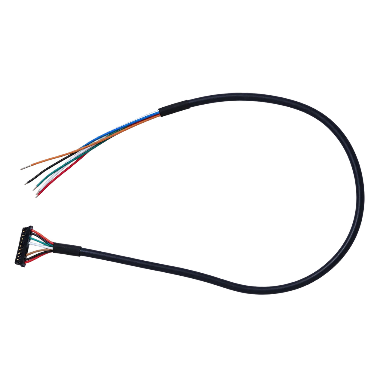
OEM component reference: the AeroMini USB + CVBS + MIPI cable requires customer soldering. This is a cable photograph, not a finished handheld instrument or a wire-color pinout.
OEM integration reference and finished-handheld requirements
A complete ground inspection instrument needs its own display, controls, power system, enclosure and verified field workflow. The adjacent photograph shows a wiring cable for an AeroMini OEM kit, not a handheld instrument. Use the checklist below to request evidence for any finished handheld candidate; none of these complete-device capabilities follows from selecting the AeroMini core.
- Native Resolution: Request the actual detector array and pixel pitch for the proposed instrument; distinguish these from display pixels and enlarged output.
- Detector & Spectral Band: Confirm the supplied detector technology and documented spectral response for that exact instrument.
- Thermal Sensitivity: Request NETD with test temperature, F-number and applicable rate. If temperature readings are required, also obtain radiometric accuracy and calibration evidence.
- Capture, Display & Recording: Verify each operating frame rate, recording/export format and observed delay in the intended field workflow.
- Lens & Focus: Confirm the delivered lens, F-number, field of view, focus operation and any supported lens changes.
- Finished Package: Obtain complete dimensions and mass including lens and battery, documented enclosure protection, battery runtime and charging requirements.
- Field Acceptance: Test the screen and controls, image retrieval and required ground-verification procedure. Specify whether qualitative observation or calibrated temperature measurement is needed.
The comparison below separates a current 640 × 512 OEM evaluation example from the evidence required for a finished handheld instrument. AeroMini 640 does not satisfy a native 1280 × 1024 requirement, and its selected non-radiometric version does not measure temperature. No finished handheld product capability is established by the OEM example.
| Parameter | AeroMini 640: selected OEM example | Finished handheld: evidence to request |
|---|---|---|
| Intended Architecture | OEM core for a custom payload; requires host, power integration and enclosure. | Complete portable instrument with verified display, controls, power system and enclosure. |
| Sensor Type | Uncooled VOx microbolometer. | Document the detector technology of the exact instrument. |
| Array Resolution | 640 × 512 native array; does not meet a native 1280 × 1024 requirement. | Confirm native detector dimensions separately from display or exported image size. |
| Pixel Pitch | 12 µm. | Obtain the detector pixel pitch for the supplied model. |
| Spectral Band | 8–14 µm LWIR. | Obtain the documented spectral response. |
| Thermal Sensitivity (NETD) | ≤30 mK at 25 °C, F/1.0. | Obtain NETD and its test conditions; temperature accuracy requires separate evidence. |
| Frame Rate | Non-radiometric: 60 Hz factory default / 30 Hz factory option; verify each active output. | Confirm capture, display and recording rates plus observed workflow delay. |
| Selected / Delivered Optics | Selected 9 mm lens: 48.7° H × 38.6° V published field of view. | Confirm delivered focal length, F-number, field of view and focus operation. |
| Video Interfaces | USB and MIPI digital paths; analog CVBS on the selected board. Confirm format, host, firmware and simultaneous-output behavior. | Verify the built-in display, recording and data-export paths needed for field work. |
| Control Interface | Illustrated 16-pin: RS232 RX/TX; 26-pin: 3.3 V UART TX/RX. Match levels, transceiver and command protocol. | Verify buttons, menus and any documented remote-control interface. |
| Operating Power | Illustrated POWER_IN1 / POWER_IN2: 5 V inputs; never infer aircraft-bus compatibility from the family table. | Confirm battery system, approved external input, charging and runtime test conditions. |
| Module / Finished-System Mass | <20 g excluding lens and flange; obtain complete installed-assembly mass. | Obtain complete-device mass including lens, battery and required accessories. |
| Dimensions | 21 × 21 × 28 mm excluding lens and flange; request the exact 9 mm lens/board assembly drawing. | Obtain complete enclosure dimensions, handling clearances and documented protection rating. |
6. Electromagnetic Interference (EMI), Heat Dissipation, and Airborne Enclosures
An enclosed airborne payload needs thermal and electromagnetic qualification as an assembly. Evaluate image uniformity, frame integrity, communications, and camera temperature with representative enclosure conditions, power loads, radios, and motor operation. An enclosure or a shielded cable alone does not establish performance.
Thermal Conductive Dissipation in Sealed Pods
Uncooled cores still dissipate heat, but power consumption and allowable case temperature are model- and operating-mode-specific. Build the thermal budget from the selected camera, interface boards, and processor, including startup and transient loads. A sealed pod needs an assessed path for heat rejection; an ingress-protection rating is not a thermal-performance rating.
AeroMini lists typical module consumption below 0.5 W at 25 °C; this is not a complete-kit or worst-case payload ceiling. Measure the selected module, board, host and other loads through startup and operation. Its −40 to +80 °C operating range is a module statement, not proof of sealed-gimbal thermal performance, enclosure protection or weather certification.
Where permitted by the camera’s integration guide, a conductive cooling path can transfer heat to the enclosure. Review these items with the mechanical and thermal design:
- ⚙️ Thermal Interfaces: Use the designated contact surfaces and supplier-approved mechanical limits. Select interface material by thermal resistance, thickness, compression, electrical isolation, and environmental requirements; do not press pads onto unspecified components.
- ⚙️ Heat Rejection: Evaluate any chassis heat path under the worst expected ambient temperature, solar loading, and low-airflow conditions, including operation on the ground. Propeller wash or forward flight is not a guaranteed cooling source.
- ⚙️ Temperature Uniformity: Follow the camera and lens supplier’s mounting and thermal recommendations. Check image drift and focus across temperature changes; arbitrary thermal isolation of the lens or sensor can conflict with the intended design.
Electromagnetic Interference (EMI) Mitigation
Transmitters, switching power electronics, and high-speed digital circuits can couple interference into a payload or its neighbors. GNSS reception may also be affected by emissions from the payload. Identify the actual sources, cable routes, return paths, and susceptibility of the installed system rather than assuming one radio-frequency configuration.
Image artifacts, dropped frames, or resets may come from power integrity, signal integrity, software, or electromagnetic coupling. Investigate them systematically. The following are design review points, with implementation taken from the applicable hardware documentation:
- ⚙️ Enclosure and Bonding: Assess shielding continuity, seams, apertures, connector entry points, and specified bonding surfaces. Coatings and joints affect electrical contact; simply choosing anodized aluminum does not create a verified shield.
- ⚙️ Harness Design: Match cable type, impedance, shielding, termination, routing, and bend radius to the selected interface and moving assembly. Verify the installed link with representative motor and radio activity.
- ⚙️ Return-Path Design: Review power returns and signal references using the board and camera integration guides. Avoid routing high-current motor returns through sensitive circuitry, but do not arbitrarily split reference planes or disconnect required returns. Confirm the final arrangement by measurement.
7. Frame Rates, Export Review, and Procurement Documentation
For procurement, establish the exact camera model and configuration, origin, destination, end user, and intended civil end use. Ask the supplier and the responsible compliance team for the applicable jurisdiction, classification, and shipment documentation under current rules. A thermal-camera description does not by itself establish whether a product is subject to the EAR, ITAR, or another country’s controls. The BIS classification guidance explains why item-specific technical information matters.
9 Hz and 50 Hz: Imaging Requirements and Document Review
Separate the imaging requirement from the export review. Frame rate influences how often images update, while motion blur and total delay also depend on detector response, acquisition timing, processing, and transport. For purchasing, request the classification and document requirements for the exact offered configuration:
- ⚙️ Lower Frame Rates: A 9 Hz stream updates about every 111 ms, which may limit a moving-scene workflow but does not by itself make stabilization or observation impossible. It is not a universal export exemption: EAR §744.9 includes restrictions involving certain cameras at or below 9 Hz. Obtain the applicable review rather than assuming minimal paperwork.
- ⚙️ Higher Frame Rates: A 50 Hz stream has a 20 ms frame period and can provide more frequent image updates. It does not guarantee blur-free imagery or 20 ms end-to-end latency. Neither 50 Hz alone nor a marketing label assigns an ECCN or makes an end-user certificate universally mandatory. Request the classification, any required authorization, and buyer/supplier document requirements for the actual transaction.
The selected non-radiometric AeroMini configuration is 60 Hz by factory default, with a 30 Hz factory option. Those rates are separate from the generic 9 Hz and 50 Hz examples above; confirm the delivered rate on each intended output and review the actual transaction’s documentation.
Buyer Requirements and Section 889 Documentation
If a buyer invokes Section 889 or related procurement restrictions, identify the actual contract clauses and requested representations. FAR 52.204-25 addresses defined covered telecommunications and video-surveillance equipment and services; it is not a blanket certification for every thermal component. Obtain model-specific manufacturer, origin, supply-chain, and compliance information requested by that buyer, and have the responsible procurement team review it. This guide does not establish any featured product’s eligibility or promise an “NDAA Declaration of Conformity.”
Use the CAMCUDA Support Center to request the matching technical and procurement documents. The CAMCUDA Privacy Policy concerns personal-data handling and does not establish export classification or procurement eligibility.

8. Frequently Asked Questions (FAQ) for Payload Integrators
How do I select an OEM thermal module that avoids overloading a multi-rotor brushless gimbal?
Budget the complete moving assembly, including lens, enclosure, mounts, interface boards, cables, and cooling. Calculate inertia about each gimbal axis and check balance, motor torque and temperature, structural resonances, and controller tuning. Inertia affects acceleration torque; static holding torque depends on imbalance and other loads. A lightweight core alone cannot eliminate jitter. Match the power path to the camera’s documented limits: a 6S pack charged to 4.2 V per cell reaches 25.2 V, so a 5–24 V input specification does not justify direct connection or automatic removal of external regulation.
For AeroMini, <20 g and 21 × 21 × 28 mm exclude the lens and flange; obtain the selected 9 mm assembly’s full mass and dimensions. Its illustrated POWER_IN1 / POWER_IN2 inputs require 5 V, so design the power path for those specific inputs.
What digital video interface is best for connecting an infrared drone core to an onboard companion computer?
Choose a camera output that the host can receive with a documented electrical interface, pixel format, timing, and driver. BT.1120 and CSI-2 names do not guarantee radiometric data or a fixed latency, and an FPGA bridge needs its own feasibility and timing checks. Measure the full camera-to-application delay. For a rotating connection, qualify the selected SDI or other link with its actual slip ring and cabling. Camera control through MAVLink requires implemented commands and compatible camera-manager, flight-stack, and ground-station support.
The selected AeroMini board has USB + CVBS + MIPI paths; confirm the actual format, firmware and host support. It does not establish BT.1120, SDI, Camera Link, calibrated radiometry or RAW output. Consult the AeroMini SDK FAQ for the matching developer-resource entry.
How does a 50 Hz frame rate affect aerial thermography, and what are the export implications?
A 50 Hz stream provides a new frame every 20 ms, compared with about 111 ms at 9 Hz. More frequent updates can help with moving scenes, but detector response, acquisition timing, stabilization, and pipeline delay still matter. Frame rate alone does not determine export classification or document requirements, and 9 Hz is not a universal exemption. Obtain the exact model’s classification and the documents required for its origin, destination, end user, and civil end use before procurement and shipment.
A 50 Hz rate is not universally critical; select the rate against the measured workflow. The current non-radiometric AeroMini example is 60 Hz by factory default or 30 Hz by factory option, not a 50 Hz product claim.
How do I calculate the required lens focal length for human and vehicle detection using Johnson’s Criteria?
Start with the observed critical dimension and an explicitly defined sampling requirement. For small angles, n_px ≈ f·H_c/(p·R), using the same units for f and p and the same units for H_c and R. A line-pair cycle requires at least two samples in an idealized model, so cycles cannot be substituted directly for pixels. For the hypothetical native 1280×1024, 12 µm array in Section 3, a 25 mm lens gives about 34.15° × 27.61° geometric FOV, 0.480 mrad central IFOV, and 48 mm per pixel on the stated plane at 100 m. These are sampling calculations, not human or vehicle detection guarantees. Validate any DRI requirement with representative scenes and a stated test method.
The native-1280 geometry does not make AeroMini 640 a native-1280 camera. For its selected 9 mm lens, the separately published field of view is 48.7° H × 38.6° V; do not substitute the hypothetical 1280-array result.
📚 References & Further Reading
- Industry Standard: MIPI CSI-2 Specification • Mobile Industry Processor Interface Alliance
- External Vendor Example: Workswell Thermal Imaging Products • Separate supplier information, not an industry standard or CAMCUDA capability verification
- Related Guide: OEM Infrared Camera Module Buying Guide • Technical Sourcing Parameters
- Product Documentation: CAMCUDA Engineering Support & Downloads • Request documents for the selected model and transaction
- Privacy & Data: CAMCUDA Privacy Policy • Personal-data handling information