Infrared temperature measurement: radiometry explained
A radiometric thermal camera estimates surface temperature from a calibrated infrared signal. Reliable results depend on the camera configuration, target emissivity, reflected radiation, optical path and measurement conditions.
In this article
What is radiometric infrared temperature measurement?
Radiometric thermography estimates temperature from a calibrated infrared signal. A thermal image shows spatial differences in detected radiation; a radiometric measurement also needs the camera’s response model, calibration data and the relevant scene parameters. For an opaque target, the result concerns its surface under the stated measurement conditions.
The measurement chain is scene radiation → optics and detector → digital signal → radiometric calibration → scene compensation → temperature estimate. Image palettes and automatic contrast can make a scene easier to interpret, but they do not establish the units of a pixel. Likewise, a 16-bit capture format does not establish a temperature-conversion formula. See RAW thermal data and Y16 before designing the host software.
Choose the exact radiometric configuration and verify its temperature-data interface. Resolution, NETD, a shutterless mode or a RAW output option alone does not establish calibrated temperature measurement.
Research basis: Yu et al., Section 2, pp. 879–880 [1]. Calibration traceability context: NIST [2].
Single-band, total-radiation and two-colour methods
The review distinguishes brightness/radiance temperature, total-radiation temperature and two-colour temperature. These are useful physical categories, but the signal model must match the instrument’s actual spectral response. An 8–14 µm camera integrates a finite wavelength band; it does not collect all thermal wavelengths.
| Approach | Information used | Condition to check |
|---|---|---|
| Brightness or band-radiance temperature | A calibrated signal in a specified spectral band, referenced to blackbody radiation. | Apparent temperature and corrected surface temperature differ when emissivity, reflected radiation or the path are not accounted for. |
| Total-radiation model | The ideal blackbody’s emission integrated over all wavelengths. | The Stefan–Boltzmann relationship uses absolute temperature. A finite-band thermal camera needs its own spectral-response and calibration model. |
| Two-colour / ratio thermometry | The relationship between calibrated signals in two infrared bands. | Any cancellation of emissivity depends on the emissivity ratio and other model assumptions. Different path transmission, reflections and low signal can still affect the result. |
Two-colour thermometry is not obtained by changing a palette or combining a visible camera with one thermal camera. It requires suitable spectral measurements and their calibration. The CAMCUDA configurations compared below are published as LWIR modules; an 8–14 µm band label is not evidence of a two-band ratio-thermometry function. [1, pp. 878–880]
Why a thermal pixel contains more than target emission
A camera can receive radiation emitted by the target, radiation reflected by its surface and radiation contributed by the intervening path. A protective window or added optic can introduce further transmission and emission terms. The relative contributions depend on the setup. [3]
One way to express the band-sensitive response is:
S = F( ∫ R(λ) · Lscene(λ) dλ ; camera state )Here R(λ) represents the effective spectral weighting and Lscene(λ) the radiance reaching the instrument. The function and operating state represent the real camera’s response, gain, offsets and relevant temperature dependence. This is a conceptual model, not a universal SDK conversion equation. Its implementation depends on the delivered device and calibration. [1, p. 880] [4]
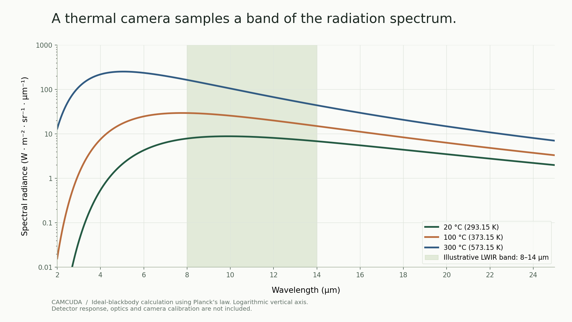
The review explicitly notes that the all-wavelength σT⁴ law cannot be substituted directly for a band-limited camera response. Its bTⁿ expression is a fitted model over a specified range. A fitted exponent, polynomial or lookup table is not a universal physical conversion from grayscale to Celsius. [1, p. 880]
Blackbody calibration: geometry, fitting and validation
The paper describes an extended-source method and a distant point-source method. In the extended-source arrangement, a reference blackbody fills the calibration field. The point-source arrangement relates an unresolved source’s radiance, projected area and distance to irradiance at the entrance pupil. These geometries should not be interchanged without the corresponding model. [1, p. 879]
The full-field condition is about that calibration arrangement. It does not mean every practical inspection target must fill the entire image. The useful question in a measurement is whether the selected region receives sufficient radiation from the target, with focus, optical spread and surrounding contributions controlled. Also, the paper’s point-source inverse-square relation is not an inverse-square correction to the temperature of a resolved surface.
Lookup tables and fitted curves
A lookup table stores a calibrated relationship between signal and reference temperature; interpolation supplies intermediate values. A fitted model approximates that relationship with a selected function. Either approach needs appropriate calibration samples and validation. Neither a table nor a polynomial is inherently a guarantee of low or high accuracy.
Three samples may determine three fitted parameters mathematically, but that does not demonstrate measurement performance between samples, across the image or across ambient conditions. High-order fits can also behave poorly outside their validated region. Check residuals and independent validation points rather than selecting a model only by its fit order. [1, pp. 879–880]
What to establish for the assembled system
- Reference: the blackbody’s calibration, effective emissivity, uniformity and uncertainty.
- Geometry: the source size, focus, distance, viewing angle and measurement region.
- Operating state: gain/range, warm-up, module temperature, firmware, lens and any added window.
- Validation: independent temperature points, spatial variation, repeatability and relevant environmental changes.
NUC or a shutter correction addresses detector non-uniformity; it does not, by itself, establish a new traceable radiometric calibration. NIST’s calibration work highlights uncertainty evaluation and optical point-spread effects as part of the measurement procedure. [2] [5] Read the related calibration, NUC and FFC terms.
The error sources to control before quoting a temperature
| Factor | What can change | Practical check |
|---|---|---|
| Emissivity & reflection | A low-emissivity surface can reflect a substantial part of the surrounding radiation. | Establish suitable surface parameters and reflected apparent temperature. Do not use one material setting for every finish or viewing condition. |
| Atmospheric path | The path can attenuate target radiation and contribute its own radiation. | Check distance, humidity and air temperature where relevant to the measurement setup. |
| Added window or optic | Transmission and temperature of an external element can alter the received signal. | Use verified LWIR transmission data and the appropriate compensation or system calibration. |
| Target size & focus | Pixels can contain mixed target/background signals; optical spread adds another contribution. | Validate the measurement region at the intended distance and focus. A single geometric pixel is not an accuracy specification. |
| Ambient state & gain | Warm-up, module heating and a changed range can alter the applicable response. | Test the intended enclosure and measurement ambient range with the selected gain/range. |
| Data interpretation | A word may represent grayscale, encoded temperature or another documented quantity. | Confirm the exact format, metadata and SDK conversion for the delivered firmware. |
Emissivity and path compensation follow the scene model described in FLIR’s measurement documentation; spatial and optical uncertainty also require attention. These checks do not imply that every CAMCUDA model exposes every compensation parameter through the same API. [3] [5]
NETD, accuracy and resolution describe different things
NETD describes sensitivity to small temperature differences under stated test conditions. Temperature accuracy describes how closely a measurement corresponds to a reference within its specified conditions. An uncertainty budget also considers the reference, scene parameters, optics, spatial mixing and repeatability. A 40 mK NETD figure cannot be read as a ±0.04 °C temperature-accuracy claim.
Detector resolution describes the physical array. It is separate from an upscaled video stream and from the size of a target that can be measured reliably. For example, a 12 µm pixel with a 15 mm lens has an approximate on-axis IFOV of 0.8 mrad: at 10 m, about 8 mm of geometric sampling per pixel. This calculation excludes blur, focus, target contrast and the required measurement region; it does not establish an 8 mm accurate-measurement spot.
Use the thermal imaging calculator for geometric coverage estimates, then validate the actual measurement setup. A camera’s detector rate, encoded-video rate and fresh calibrated temperature-update rate must likewise be confirmed separately.
CAMCUDA radiometric thermal camera module comparison
The table compares currently published CAMCUDA configurations, checked on 30 October 2026. These are product-page specifications, not results of an independent side-by-side laboratory test. A family option applies only when that radiometric configuration is supplied. Older document revisions can describe a different assembly or firmware.
The table scrolls horizontally on small screens. Object-temperature ranges are separate from ambient operating limits.
| Model / measurement boundary | Native array / pitch | Published object-temperature ranges | Published accuracy & conditions | Data path & rate scope | Integration decision |
|---|---|---|---|---|---|
| AirTiny213 mm core[P1] | 256 × 192 / 12 µm | −20 to +150 °C; +50 to +550 °C | Typical ±2 °C or ±2%, whichever is greater. Measurement ambient −10 to +70 °C is listed separately; confirm complete test conditions. | DVP / VOSPI / MIPI / USB options. ≤25 Hz detector rate; match the adapter, data mode and conversion. | Compact 256-array radiometric integration; confirm the delivered optics and board. |
| SuperMini 640TUltra-light core[P2] | 640 × 512 / 8 µm | −20 to +150 °C; +100 to +650 °C | Typical ±2 °C or ±2% of reading; ambient −20 to +60 °C. The page does not define a greater-of rule. | 30 Hz thermographic model. CDS3 / MIPI temperature-data paths; optional matched USB board. | 640-array thermography with a compact core; account for supply rails, interface timing and parsing. |
| ThermoCore 640 — listed Type-C radiometric configuration[P3] | 640 × 512 / 12 µm | −20 to +150 °C | Not specified in the supplied current datasheet. Request configuration-specific accuracy and calibration evidence. | Radiometric USB UVC / RAW 14- or 16-bit listing; 25 Hz. Confirm the actual host buffer and temperature conversion. | USB RAW integration where the matched SDK and numerical data path can be verified. |
| ThermoCore IP 384Radiometric Ethernet[P4] | 384 × 288 / 17 µm | −20 to +150 °C; 0 to +550 °C | Not specified on the current public product page. Confirm the delivered calibration. | Ethernet and radiometric SDK. Main H.264 stream: 720 × 576 at 25 fps; this is not the native array or a temperature-update guarantee. | Networked monitoring; specify the numerical temperature API and alarm requirements. |
| AeroMini 640 — radiometric enquiry option[P5] | 640 × 512 / 12 µm | −20 to +550 °C family listing; confirm calibrated sub-ranges | Numerical accuracy requires confirmation for the offered radiometric configuration. | 25 Hz radiometric listing. Interface, SDK and RAW format require confirmation; imaging-kit interfaces cannot be assumed. | Separate configuration/availability enquiry; identify the complete measured-data path before selection. |
| SuperMini 640 — imaging-only comparison[P2] | 640 × 512 / 8 µm | No temperature measurement | Not applicable to thermometry. The 640T specification does not apply. | 50 Hz imaging model; BT.656 / MIPI imaging paths. | Thermal imaging where calibrated temperature data is not required. |
Accuracy wording is preserved by model. Where a current public page does not state accuracy or an interface, it is marked for confirmation rather than inferred from another product. A published typical accuracy is not the uncertainty of every field installation.
Which integration path should you investigate?
- A compact 256 × 192 design: investigate AirTiny2, then match its lens, board and temperature mode. View configuration →
- A 640 × 512 thermographic core: investigate SuperMini 640T when its documented data path and power requirements fit the host. View configuration →
- A radiometric USB RAW design: investigate the listed ThermoCore 640 configuration, with a sample buffer and SDK confirmation. View configuration →
- A networked inspection system: investigate ThermoCore IP 384, confirming the temperature-data API separately from H.264 video. View configuration →
For AeroMini, separate the available non-radiometric imaging configuration from the radiometric enquiry path. For SuperMini, specify 640T when temperature data is required. For a USB or network design, confirm both the numerical data format and control/compensation API before choosing the host architecture.
Browse the official Download Center for matched specifications, drawings and SDK material, or use the CAMCUDA enquiry form to confirm the delivered configuration.
What the review does—and does not—establish for an OEM module
Yu and colleagues connect measurement theory, radiometric calibration and examples of commercial instruments. The most useful integration lesson is to treat the camera, calibration and measurement scene as one system. The review is a strong starting point for understanding the chain; its historical product tables are not a current market ranking or an equivalence test between research cameras and OEM modules. [1]
Its discussion of superframing, MicroScan and HDR concerns specific instrument designs. InfraTec, for example, describes HDR acquisition with different integration times and filters. Such acquisition and calibration mechanisms are different from changing a colour map or selecting a wider displayed temperature scale. None of those research-camera features is established for the CAMCUDA modules in this comparison merely because they appear in the review. [1, pp. 880–883] [6]
Similarly, two-colour methods need suitable measurements and assumptions; an improved result reported for a particular experiment cannot be transferred to another detector, material or working distance. Validate the actual application rather than transferring a percentage from a research example.
A verification checklist before an OEM design freeze
- Define the measurement. Record the target material and finish, temperature span, smallest measurement region, working distance and required accuracy.
- Freeze the configuration. Identify the exact radiometric model, lens, board, gain modes, firmware and host SDK. Obtain the corresponding calibration and format documents.
- Validate the assembled optical path. Include the final window, enclosure, focus and heat path. Check warm-up and relevant ambient conditions.
- Test against a suitable reference. Use a documented blackbody arrangement and independent validation points across the required range. Record spatial variation and repeatability.
- Verify the data pipeline. Check units, metadata, timestamps, correction events and actual fresh-temperature delivery. Distinguish a repeated display image from a new sample.
- Record the conditions with the result. Keep the configuration, compensation settings, reference information and measurement conditions with each acceptance record.
This is a proposed integration verification plan, not a claim that a new CAMCUDA test campaign was performed for this article. For firmware-specific operations, follow the matching product manual and SDK.
Questions about infrared temperature measurement
Can a non-radiometric thermal camera measure temperature?
Not from its thermal image alone. Calibrated temperature measurement requires an appropriate radiometric model, calibration information and data path. A visually useful image or a RAW grayscale output does not establish those capabilities.
Does lower NETD mean better absolute temperature accuracy?
No. NETD describes thermal sensitivity under stated conditions. Absolute measurement performance also depends on calibration, emissivity, reflections, optics, the measurement region and the environment.
Can I convert any Y16 value directly to degrees Celsius?
No. Y16 specifies a sample container, not universal units. Use the delivered mode’s format and SDK documentation to determine whether its words are grayscale, encoded temperature or another quantity.
Does a radiometric camera correct emissivity automatically?
Not necessarily. Determine which compensation parameters the delivered firmware and SDK expose, and supply appropriate values for the actual scene. Radiometric capability alone does not establish automatic material identification.
Is SuperMini 640 the same thermographic model as 640T?
No. The current product page distinguishes imaging-only SuperMini 640 at 50 Hz from thermographic SuperMini 640T at 30 Hz. Select the model before applying temperature ranges or data-conversion instructions.
Can an 8–14 µm module perform two-colour thermometry?
Not merely because it covers that wavelength interval. Two-colour thermometry needs appropriately separated spectral measurements, their calibration and a justified model. The module’s ordinary LWIR band specification does not establish that function.
Related concepts and engineering resources
For practical calculations, continue to the thermal imaging calculator. For implementation topics, browse Engineering Guides and the Download Center.
Sources, scope and document versions
- Yu Shuang, Zhang Runqi, Li Gen, Li Yating, Xu Heding, Hong Wenqing and Su Lan. Temperature Measurement Based on Infrared Thermal Imaging / 基于红外热成像的温度测量技术. Infrared Technology, 2026, 48(7): 877–885. The supplied full paper was reviewed; this article is an original engineering synthesis and does not reproduce its figures or product tables.
- NIST. Radiation Thermometry. Reference blackbodies and calibration traceability.
- FLIR. Thermographic measurement techniques, Section 12. Scene parameters, reflected apparent temperature and atmospheric/optical contributions.
- NIST. Technical Note 1621. Detector-based radiance responsivity and integration of Planck radiance. The blackbody chart here is an independent calculation using exact SI constants.
- Lane, B. M. and Whitenton, E. P. Calibration and Measurement Procedures for a High Magnification Thermal Camera. NISTIR 8098, 2016. DOI: 10.6028/NIST.IR.8098.
- InfraTec. HDR – Simultaneous Mapping of Wide Temperature Ranges. A manufacturer example of a specific HDR instrument architecture.
Model-specific CAMCUDA references
- [P1] CAMCUDA AirTiny213 mm core. Current public configuration and comparison source. Product information · USB adapter schematic
- [P2] CAMCUDA SuperMini 640TUltra-light core. Current public configuration and comparison source. Product Manual V1.0.0 (January 2026 edition) · Mechanical drawing
- [P3] CAMCUDA ThermoCore 640 — listed Type-C radiometric configuration. Current public configuration and comparison source. Integration datasheet (26 × 26 mm reference core)
- [P4] CAMCUDA ThermoCore IP 384Radiometric Ethernet. Current public configuration and comparison source. Integration datasheet
- [P5] CAMCUDA AeroMini 640 — radiometric version. Current public configuration and comparison source. AeroMini640 datasheet / family reference
Product-page comparison checked 30 October 2026. Confirm the serial/configuration-specific calibration, firmware and interface with the supplied documentation. This page reports published specifications and an engineering reading of the cited sources; it does not report new product-performance measurements.