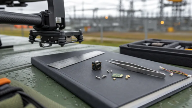
Drones with Thermal Imaging: OEM Payload Selection & Integration Guide
Drones with Thermal Imaging: OEM Payload Selection & Integration Guide
The rapid evolution of uncooled Long-Wave Infrared (LWIR) sensor technology has completely upended airborne surveillance, perimeter security, industrial utility inspection, and search-and-rescue (SAR) missions. For hardware architects and UAV systems engineers, integrating thermal imaging into an airframe is no longer about slapping on an overpriced, locked-down commercial payload pod. Modern uncooled Vanadium Oxide (VOx) focal plane arrays deliver full 640×512 resolution at a tight 12 μm pixel pitch in sub-miniature form factors. This lets you build custom sensor rigs that squeeze maximum flight endurance out of your battery packs while keeping your Size, Weight, Power, and Cost (SWaP-C) budget locked down.
Here’s the deal: getting an OEM thermal core to actually work reliably on an unmanned aerial vehicle (UAV) is a balancing act of nasty engineering trade-offs. You are juggling optical field-of-view (FOV), Instantaneous Field of View (IFOV), sensor thermal sensitivity (Noise Equivalent Temperature Difference, or NETD), signal processing pipeline latency, electrical communications (analog CVBS vs. digital MIPI/DVP), and high-frequency motor vibration isolation. If you mess up your power filtering or get lazy with mechanical damping, your thermal feed will turn into a blurry, noisy mess the second your brushless motors spin up. This guide breaks down the exact hardware engineering principles, physics calculations, and integration blueprints you need to spec, mount, and deploy OEM thermal cores for industrial, tactical, and sub-250g drone platforms.
Table of Contents
- 👉 1. Sensor Physics & LWIR Detector Architecture for UAVs
- 👉 2. SWaP-C Engineering: Payload Optimization & Sub-250g Compliance
- 👉 3. Optical Engineering & Johnson’s Criteria Range Calculation
- 👉 4. Video Transmission Pipelines: Analog CVBS vs. Embedded Digital Streams
- 👉 5. Mechanical, Thermal, and Electrical Integration Strategies
- 👉 6. Edge AI Target Detection and Radiometric Measurement
- 👉 7. OEM Thermal Core Benchmark: W640-TIF-K1 vs. AeroMini 640
- 👉 8. Step-by-Step OEM Payload Integration Checklist
- 👉 9. Technical FAQ for UAV Thermal Payload Engineers
1. Sensor Physics & LWIR Detector Architecture for UAVs
Airborne thermal imaging operates squarely within the Long-Wave Infrared (LWIR) atmospheric transmission window (8 to 14 μm). Look, standard visual-light electro-optical (EO) cameras rely on reflected ambient sunlight or active illumination bouncing off a target. LWIR sensors don’t care about ambient light. They passively detect raw blackbody radiation emitted by anything with a temperature above absolute zero (−273.15 °C). On an active drone mission, this physics profile cuts straight through atmospheric smoke, dense fog, dust storms, and pitch-black conditions without giving away your aircraft’s position with an IR illuminator.

Microbolometer Physics: Vanadium Oxide (VOx) vs. Amorphous Silicon (a-Si)
At the center of any modern thermal drone payload sits an uncooled microbolometer focal plane array (FPA). In this array, every single pixel is a microscopic suspended membrane made of an IR-absorbing material held above a silicon substrate by micro-machined isolation legs. When LWIR radiation hits that membrane, its temperature climbs by fractions of a millikelvin, which directly changes the electrical resistance of the underlying thermistor material.
When you are evaluating cores for aerospace applications, Vanadium Oxide (VOx) is the clear winner over legacy amorphous Silicon (a-Si) for several core physical reasons:
- ✅ Temperature Coefficient of Resistance (TCR): VOx delivers a significantly higher TCR (typically −2% to −3% per Kelvin). That means you get a much stronger voltage delta per millikelvin of target temperature change compared to a-Si. For drone pilots, this yields superior thermal sensitivity (NETD ≤ 40 mK to ≤ 50 mK at f/1.0), allowing the sensor to pick up minute thermal differences under 0.04 °C across low-contrast surfaces like open water, dense forest canopies, or uniform concrete tarmac.
- ✅ Low 1/f Flicker Noise: VOx material physics exhibit much lower low-frequency flicker noise. When your drone is whipping around on a rapid yaw or sweeping across a massive perimeter, low 1/f noise prevents horizontal streaking, rolling bands, and fixed pattern noise across your video feed.
- ✅ Wafer-Level Packaging (WLP): Modern WLP manufacturing lets fabricators build 12 μm pixel pitch arrays in featherweight footprints. Shrinking pixel pitch down to 12 μm allows a full 640×512 array to fit on an active sensing area of just 7.68 × 6.144 mm. That cuts down the physical diameter and glass weight of the required Germanium optics dramatically.
Readout Integrated Circuit (ROIC) and Onboard Signal Processing
Those microscopic resistance shifts across the VOx grid are measured by a Readout Integrated Circuit (ROIC) bonded directly under the detector array. Before that raw electrical signal ever leaves the core as a usable composite video signal or digital bus, it passes through several onboard hardware processing steps:
- ⚙️ Bias Pulse & Analog Integration: Highly stable constant-current or constant-voltage pulses bias each pixel during the integration window, collecting charge across onboard sample-and-hold capacitors.
- ⚙️ High-Precision Digitization (ADC): Onboard 14-bit or 16-bit analog-to-digital converters digitize the tiny charge levels, preserving the full dynamic range of the thermal landscape without clipping cold skies or hot targets.
- ⚙️ Non-Uniformity Correction (NUC): Semiconductor manufacturing variations mean every single microbolometer pixel has slightly different baseline resistance and gain curves. Two-point factory calibration matrices normalize these differences across the entire operational temperature envelope.
- ⚙️ Bad Pixel Replacement (BPR): Dead, drifting, or noisy pixels are flagged at the hardware level and continuously interpolated from healthy neighboring pixels in real time.
- ⚙️ Dynamic Detail Enhancement (DDE) & AGC: The core maps the wide-dynamic-range 14-bit infrared sensor data into an 8-bit visual stream (256 shades of grey or false-color palettes) using contrast-preserving histogram equalization algorithms. This keeps hot human targets crisp and recognizable without washing out cool ground terrain.
In-Flight Non-Uniformity Correction (NUC) and Shutter Management
In the shop, we see this all the time: an engineer tests a thermal core on a bench and it looks flawless, but five minutes into flight the image degrades into a hazy screen of horizontal lines. That happens because microbolometers drift as the drone’s battery, avionics, and ESCs heat up the internal airframe, and prop-wash rapidly cools the camera housing from the outside.
To eliminate this spatial drift, thermal cores execute periodic NUC calibrations using an internal electromechanical shutter blade. The shutter drops into the optical path for 200 to 500 milliseconds, presenting an isothermal black surface to the FPA to re-zero pixel offset baselines. But on an autonomous drone mission or high-speed manual approach, an unexpected shutter freeze during final descent or target tracking can cause a crash or loss of tracking. Cores like the CAMCUDA W640-TIF-K1 feature intelligent threshold-based shutter routines that minimize calibration freeze intervals while keeping thermal imagery razor-sharp across dynamic flight regimes.
2. SWaP-C Engineering: Payload Optimization & Sub-250g Compliance
In UAV engineering, weight is your absolute enemy. Every single gram of unnecessary payload eats away at battery flight time, forces your propulsion system to draw higher continuous amps, and pushes you into larger, more expensive airframe classes. Even more critically, payload mass dictates whether your drone falls under heavy commercial regulations or stays inside the sub-250g category. Under FAA Part 107 (US) and EASA Open Category A1/C0 (Europe), aircraft weighing strictly under 249 grams All-Up-Weight (AUW) bypass complex pilot licensing, remote ID mandates, and operational safety distance restrictions.
Sub-250g All-Up-Weight (AUW) Mass Budget Breakdown
Building a sub-250g thermal quadcopter that actually delivers professional 640×512 imaging requires strict mass partitioning. Every screw, wire harness, ESC capacitor, and carbon plate must be budgeted down to the tenth of a gram:
- ⚙️ Carbon Fiber Frame & Fasteners: ~45 to 55 g
- ⚙️ Brushless Motors (1404 / 1504 size) & Propellers: ~45 to 50 g
- ⚙️ Avionics Stack (AIO Flight Controller + 20A ESC + ELRS RX): ~15 to 20 g
- ⚙️ 5.8 GHz Analog Video Transmitter (VTX) & Antenna: ~8.5 g
- ⚙️ Flight Battery (High-Energy Density 2S/3S 850–1100 mAh LiPo/Li-Ion): ~65 to 75 g
- ✅ Allocated Payload Margin for Thermal Core & Mount: 50 to 60 g
That leaves you with a razor-thin 50 to 60-gram window for your entire thermal payload system—including the lens, internal electronics, ruggedized chassis, and wiring harness. The CAMCUDA W640-TIF-K1 thermal core hits an all-up mass of exactly 56.5 g with its factory-fitted 9 mm Germanium optic and aluminum enclosure installed. This tight weight profile allows OEM engineers to build a fully capable, compliant sub-250g tactical reconnaissance drone without stripping out resolution or structural integrity.
Power Rail Architecture and Electrical Efficiency
Thermal FPAs are sensitive analog detectors. If your electrical architecture is sloppy, the massive 24 kHz to 48 kHz switching noise generated by your brushless motor ESCs will bleed directly into the core’s microbolometer bias rails, manifesting as ugly scrolling lines on your video downlink. Here is how to engineer your power rails cleanly:
- ✅ Wide-Voltage Direct Battery Integration: Modules engineered with wide input voltage regulators—such as the 5–18 V DC input on the W640-TIF-K1—can run straight off unregulated 2S, 3S, or 4S flight battery packs. Bypassing external DC-DC buck-boost boards eliminates 5 to 10 grams of extra PCB weight and removes a secondary switching regulator noise source entirely.
- ✅ Thermal Core Power Dissipation ($P_d$): In sealed drone canopies or micro-gimbal pods where passive airflow is restricted, you must select cores that draw under 0.8 W. Running a 0.8 W core on an 850 mAh 3S LiPo pack draws roughly 72 mA, which accounts for less than 3% of your total flight power budget during a 20-minute mission.
3. Optical Engineering & Johnson’s Criteria Range Calculation
You cannot use standard visible-light glass for LWIR thermal imaging. Common optical glasses like BK7 or fused silica act like solid brick walls to infrared wavelengths between 8 and 14 μm. Instead, drone thermal optics are precision-ground from single-crystal Germanium (Ge) or specialized chalcogenide glass matrices. These lenses require Anti-Reflective (AR) and Diamond-Like Carbon (DLC) hard exterior coatings to maximize photon transmission while surviving high-speed prop-wash dust and sand impacts, conforming to standards established by optical institutions like Optica.
Calculating Instantaneous Field of View (IFOV)
Instantaneous Field of View (IFOV) represents the exact spatial angle captured by a single pixel on the focal plane array. It is the core mathematical metric you use to figure out your drone’s ground resolution at any flight altitude or standoff distance ($D$):
$$\text{IFOV (mrad)} = \left(\frac{\text{Pixel Pitch } d}{\text{Focal Length } f}\right) \times 1000$$
Let’s run the real numbers for a 12 μm ($0.012\text{ mm}$) pixel pitch sensor equipped with a 9 mm focal length Germanium lens:
$$\text{IFOV} = \left(\frac{0.012\text{ mm}}{9.0\text{ mm}}\right) \times 1000 = 1.33\text{ mrad}$$
Now, calculate your single-pixel ground footprint (Ground Sampling Distance) from an operational flight ceiling of 100 meters ($D = 100\text{ m}$):
$$\text{Spot Size} = D \times \left(\frac{\text{IFOV}}{1000}\right) = 100\text{ m} \times 0.00133 = 0.133\text{ m} = 13.3\text{ cm per pixel}$$
Johnson’s Criteria Target Calculations (1.8 m Human Target)
Johnson’s Criteria defines the statistical probability (at a standard 50% confidence level) of detecting, recognizing, and identifying targets based on the number of resolved line pairs (cycles) projected across the target’s critical dimension. For a standard 1.8-meter upright human target, the calculated operational standoff distances for a 640×512, 12 μm core with a 9 mm optic are detailed below:
| Resolution Level | Johnson Cycle Criteria | Pixels Across Target | Calculated Standoff (9 mm Optic) | Real-World Operational Meaning |
|---|---|---|---|---|
| Detection | 1.5 cycles | 3.0 pixels | 900 m | Pilot flags an anomalous heat blob distinct from background clutter. |
| Recognition | 6.0 cycles | 12.0 pixels | 225 m | Pilot confirms object type (human biped vs. deer vs. small vehicle). |
| Identification | 12.0 cycles | 24.0 pixels | 113 m | Detailed posture, gear, or held items can be distinguished. |
Note: Real-world operational range will fluctuate depending on atmospheric attenuation (relative humidity, fog density, airborne smoke particulate) and the actual thermal differential (ΔT) between the target and its surrounding background.
4. Video Transmission Pipelines: Analog CVBS vs. Embedded Digital Streams
Selecting your core’s video interface dictates your entire avionics architecture, onboard compute hardware, flight latency, and RF downlink setup. Drone payloads generally fall into one of two camps: zero-latency analog baseband links or high-bandwidth digital processing pipelines.
For an in-depth hardware breakdown of board-level differential routing, impedance matching, and pinout assignments, check out our technical teardown on thermal camera module interfaces (USB vs MIPI vs CVBS vs DVP).
| System Architecture Metric | Analog CVBS Core (e.g., W640-TIF-K1) | CAMCUDA AeroMini 640 | CAMCUDA AeroMini 640 |
|---|---|---|---|
| Signaling Format | Baseband composite (PAL/NTSC, 1.0 Vp-p into 75 Ω) | Digital board; confirm DVP/MIPI configuration against PDF pinout | USB; confirm protocol and host driver |
| Pipeline Latency | < 5 ms (Direct real-time scanout) | Not specified; measure the complete configured pipeline | Not specified; measure the complete configured pipeline |
| Onboard Compute Overhead | Zero (Connects straight to 5.8 GHz VTX) | High (Requires FPGA or SoC with video encoder) | Moderate (SBC running Linux / UVC host stack) |
| Wiring Harness Complexity | 3 conductors (Video, Ground, Power) | Use the 26-pin connector diagram | Use the 16-pin USB/CVBS connector diagram |
| Radiometric Temperature Data | No (8-bit AGC visual stream only) | 25 Hz radiometric build only, with 9 / 13 / 18 mm; confirm data format | 25 Hz radiometric build only, with 9 / 13 / 18 mm; confirm data format |
| Ideal Drone Mission Profile | Fast tactical scouting, manual FPV piloting, SAR | Edge AI target tracking, industrial radiometric mapping | Tethered inspection drones, test bench rigs |
When you are building a fast-response scouting drone or sub-250g tactical rig, analog CVBS remains unbeatable. You solder the module’s 3-pin lead (Video, Power, Ground) straight to a high-power 5.8 GHz analog transmitter (like a TBS Unify Pro32 or Rush Tank). The video reaches your pilot goggles with sub-5ms latency, giving them the split-second reaction times needed for low-altitude maneuvering. For pre-flight electrical checks and ground loop diagnostics, review our engineering checklist on IR camera module drone OEM integration checks.
5. Mechanical, Thermal, and Electrical Integration Strategies
Drones are brutally harsh operating environments. High-frequency motor vibrations, rapid airspeed changes, and extreme thermal swings will ruin your thermal image quality if your mounting mechanics are poorly thought out.
Mechanical Vibration Isolation and Harmonic Damping
Brushless drone motors spinning at 15,000 to 30,000 RPM generate nasty high-frequency vibrations between 200 Hz and 600 Hz. These mechanical vibrations translate directly into the microbolometer’s suspended membranes, causing microphonic blurring and image artifacts across your feed.
- ⚙️ Silicone Isolator Selection: Mechanically isolate the thermal core from the airframe using tuned silicone damping balls. For payload modules weighing 50 g to 100 g, use soft silicone isolators rated between 30A and 40A Shore durometer. If you go too stiff (over 60A durometer), high-frequency motor harmonics punch right through the dampeners. If you go too soft, the camera will wobble during aggressive yaw maneuvers.
- ⚙️ Inertial Center of Gravity (CG) Alignment: If you are mounting the core on a 2-axis or 3-axis brushless gimbal, align the physical center of gravity of the camera housing perfectly with the motor pitch and roll pivot points. An unbalanced payload forces gimbal motors to draw excess holding current, creating parasitic heat and risking in-flight motor step loss.
Thermal Dissipation Inside Enclosed Drone Canopies
Even though uncooled VOx cores don’t need heavy cryogenic coolers, maintaining stable ambient thermal conditions around the housing is critical for measurement repeatability and preventing excessive NUC shutter cycles:
- ⚙️ Conductive Thermal Coupling: Use high-conductivity thermal pads (3.0 to 6.0 W/m·K) to bridge the aluminum core housing directly to the drone’s carbon fiber frame or aluminum mounting brackets, using the airframe as a natural heatsink.
- ⚙️ Prop-Wash Aerodynamic Baffling: Never expose the bare Germanium lens barrel directly to open, turbulent prop-wash. Cold, pulsating airflow over the front element creates sharp localized temperature deltas that trigger constant NUC shutter cycles. Mount your optical core inside an aerodynamically shielded cowling with controlled internal venting.
6. Edge AI Target Detection and Radiometric Measurement
Modern commercial and defense drone systems are increasingly integrating onboard edge-AI processors (such as the NVIDIA Jetson Orin Nano, Raspberry Pi Compute Module 4, or Hailo-8 M.2 accelerators) alongside digital thermal cores to run real-time computer vision pipelines autonomously.
Raw 14-Bit Pixel Streaming vs. 8-Bit Visual Feeds
Standard visual cameras output 8-bit RGB frames. Digital thermal modules, on the other hand, output raw 14-bit or 16-bit uncompressed digital numbers (DN) representing the raw infrared radiation flux striking each microbolometer pixel. Radiometric cores map these raw digital values directly to absolute temperature figures using factory calibration polynomials stored in onboard EEPROM.
When feeding thermal video into onboard neural networks (like YOLOv8 or customized MobileNet models), piping the raw 14-bit stream or an algorithmically enhanced 8-bit stream processed via Contrast Limited Adaptive Histogram Equalization (CLAHE) gives you distinct operational advantages:
- ✅ Total Lighting Invariance: Thermal-trained neural networks run with identical object classification accuracy in direct midday glare, under deep shadows, and in total zero-lux darkness.
- ✅ Sharp Thermal Edge Extraction: Heat-emitting objects (human bodies, running engines, high-voltage transformers) provide high-contrast boundaries against cool backgrounds, allowing lightweight convolutional networks to hit mean Average Precision (mAP) scores over 92% with low compute overhead.
- ✅ Automated Radiometric Threshold Triggers: Companion processors continuously scan the 14-bit array to execute autonomous flight behaviors over MAVLink (for example, ordering the flight controller to lock into an autonomous loiter pattern if any surface temperature in a substation exceeds 85 °C).
7. OEM Thermal Core Benchmark: W640-TIF-K1 vs. AeroMini 640
Choosing between a purpose-built, ultra-low-latency analog composite module and a modular digital/radiometric core comes down to your aircraft’s specific mission profile, avionics architecture, and weight budget.

W640-TIF-K1 640×512 Uncooled VOx CVBS Thermal Imaging Module
The W640-TIF-K1 is an ultra-compact uncooled VOx thermal imaging core engineered specifically for FPV scout drones, sub-250g UAVs, and direct analog video transmission payloads. Featuring a factory-fitted 9 mm Germanium lens, 60 Hz frame rate, and a direct 3-pin SMD interface with wide 5–18 V power input, it provides high-resolution 640×512 thermal imaging without requiring complex companion boards or digital decoders.
640 × 512
12 μm VOx
≤40 mK
56.5 g (Total)
Key Engineering Specifications (W640-TIF-K1)
| Detector Type | Uncooled Vanadium Oxide (VOx) Focal Plane Array |
|---|---|
| Active Array Resolution | 640 × 512 pixels |
| Spectral Band | 8 to 14 μm (LWIR) |
| Detector Frame Rate | 60 Hz |
| Optics & Field of View | 9 mm factory-fitted fixed lens (46.2° × 37.7° FOV, 1.33 mrad IFOV) |
| Human Range (1.8m Target) | Detection: 900 m | Recognition: 225 m | Identification: 113 m |
| Video Output & Pinout | Analog CVBS (PAL), 3-pin SMD 1.25mm pitch (Pin 1: CVBS, Pin 2: GND, Pin 3: Power) |
| Input Voltage & Power | 5–18 V DC wide-voltage input | ≤ 0.8 W power consumption |
| Operating Envelope & Shock | −20 °C to +60 °C | 80 g @ 4 ms mechanical shock rating |
| Physical Dimensions | 43.3 × 26 × 35 mm (Total mass: 56.5 g) |
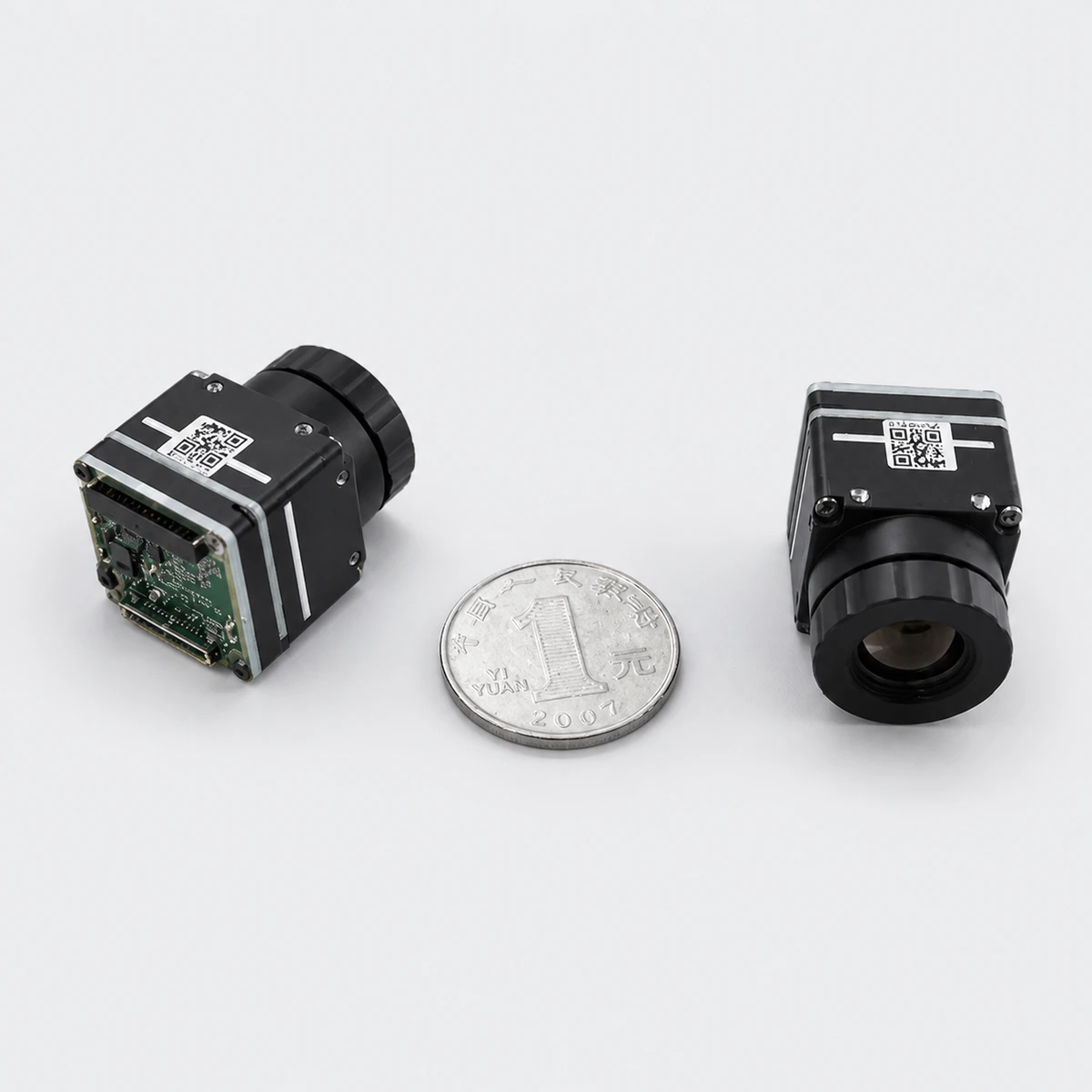
CAMCUDA AeroMini 640 · 640 × 512 / 12 μm thermal module
CAMCUDA AeroMini 640 combines a 640 × 512 VOx detector, 12 μm pixels and an 8–14 μm LWIR response. Dimensions are 21 × 21 × 28 mm and weight is under 20 g, both excluding lenses and flanges. Typical power is below 0.5 W at 25 °C. Choose 60 Hz non-radiometric imaging or 25 Hz radiometry; radiometric lenses are limited to 9, 13 and 18 mm with a −20 to +550 °C measurement range.
AeroMini 640 specification source: CAMCUDA MINI640 Integrated EN PDF. The 9 mm lens is specified at 48.7° × 38.6° H × V, F/1.0. Non-radiometric online lens options are 4, 7, 9, 13, 18, 25, 35 and 50 mm. The 7 mm FOV is 64° × 52°; the 18 mm FOV is 24.2° × 19.5°. The PDF also lists 15, 60 and 75 mm reference entries. Non-radiometric units ship at 60 Hz by default, with a 30 Hz factory option at the same price. The 25 Hz radiometric version is currently available for enquiry only, with 9, 13 or 18 mm lenses and an interface to be confirmed.
| Detector | Uncooled VOx |
|---|---|
| Resolution | 640 × 512 pixels |
| Pixel pitch | 12 μm |
| Spectral response | 8–14 μm |
| Frame rate | Non-radiometric: 60 Hz default; optional 30 Hz factory configuration. Radiometric: 25 Hz; availability enquiry only. |
| NETD | ≤50 mK at 25 °C, F/1.0; ≤40 mK optional |
| F-number | F/1.0 |
| Polarity | White hot / Black hot |
| Supply voltage | 5 V or 12 V, according to configuration; illustrated connector power pins: 5 V |
| Typical power at 25 °C | <0.5 W |
| Digital video | YUV, USB, BT.656 |
| Analog video | CVBS, PAL, NTSC |
| Serial communication | UART, RS232, RS422 |
| Dimensions | 21 × 21 × 28 mm, without lenses and flanges |
| Weight | <20 g, without lenses and flanges |
| Measurement range | −20 °C to +550 °C, radiometric version |
| Radiometric lens options | 9 / 13 / 18 mm only |
| Operating temperature | −40 °C to +80 °C |
| Storage temperature | −50 °C to +85 °C |
| Humidity | 5–95%, non-condensing |
Compare AeroMini 640 lenses and request a configuration quote →
Key Engineering Specifications (AeroMini 640)
| Detector | Uncooled VOx |
|---|---|
| Resolution | 640 × 512 pixels |
| Pixel pitch | 12 μm |
| Spectral response | 8–14 μm |
| Frame rate | Non-radiometric: 60 Hz default; optional 30 Hz factory configuration. Radiometric: 25 Hz; availability enquiry only. |
| NETD | ≤50 mK at 25 °C, F/1.0; ≤40 mK optional |
| F-number | F/1.0 |
| Polarity | White hot / Black hot |
| Supply voltage | 5 V or 12 V, according to configuration; illustrated connector power pins: 5 V |
| Typical power at 25 °C | <0.5 W |
| Digital video | YUV, USB, BT.656 |
| Analog video | CVBS, PAL, NTSC |
| Serial communication | UART, RS232, RS422 |
| Dimensions | 21 × 21 × 28 mm, without lenses and flanges |
| Weight | <20 g, without lenses and flanges |
| Measurement range | −20 °C to +550 °C, radiometric version |
| Radiometric lens options | 9 / 13 / 18 mm only |
| Operating temperature | −40 °C to +80 °C |
| Storage temperature | −50 °C to +85 °C |
| Humidity | 5–95%, non-condensing |
8. Step-by-Step OEM Payload Integration Checklist
To avoid blowing up components on the bench or getting jittery video on maiden flights, follow this field-tested engineering workflow when integrating an OEM thermal core:
- ⚙️ Optical Range & Target IFOV Modeling: Calculate your target IFOV from your intended operational ceiling and target dimensions. Confirm whether a wide 9 mm lens (wide-area search) or a telephoto optic (high-standoff powerline inspection) is necessary.
- ⚙️ SWaP-C Mass Partitioning: Weigh every subsystem on a digital scale. If you are targeting sub-250g compliance, verify that your thermal core and mounting hardware don’t exceed the 56.5 g margin.
- ⚙️ Power Rail Isolation & Filtering: If using a wide-voltage core (5–18 V), wire directly to clean battery power or a filtered VTX output. For digital cores requiring regulated 3.3 V / 5 V rails, ensure linear regulator ripple stays under 30 mVp-p to prevent microbolometer banding.
- ⚙️ Mechanical Damping & Center of Gravity: Balance the thermal module along both pitch and roll axes of your gimbal. Fit 30A–40A Shore durometer silicone damping isolators to filter out 200–600 Hz frame harmonics.
- ⚙️ Thermal Coupling & Wind Baffling: Apply thermal gap pads between the core housing and carbon airframe. Ensure the Germanium lens assembly is shielded inside an aerodynamic nosecone to prevent prop-wash turbulence from inducing NUC shutter loops.
- ⚙️ RF Grounding & EMI Verification: Ground the core’s metal chassis to common ground. Check that digital clocks don’t desensitize nearby 1575.42 MHz GPS L1 or 915 MHz / 2.4 GHz RC receivers.
- ⚙️ Downlink & Interface Verification: For analog CVBS, verify clean PAL/NTSC decoding on field monitors. For digital DVP/MIPI pipelines, verify V4L2 device drivers and test 14-bit radiometric pixel capture in Linux.
- ⚙️ Direct OEM Engineering Consultation: For custom lens calibrations, STEP CAD models, pinout documentation, or volume RFQs, reach out to the applications team at the CAMCUDA OEM engineering inquiry desk.
9. Technical FAQ for UAV Thermal Payload Engineers
What are the practical tradeoffs between analog CVBS and digital interfaces on UAV thermal payloads?
📚 References & Further Reading
- Industry Standard: Optical coatings and Germanium lens transmission standards governed by Optica.
- Industry Benchmark: Industrial thermographic standards and handheld LWIR sensor architectures by Hikmicro.
- Related Guide: IR Camera Module Drone OEM Integration Checks & Pre-Flight Diagnostics.
- Related Guide: Thermal Camera Module Interface Selection: USB vs MIPI vs CVBS vs DVP.
- OEM Engineering Support: Contact the technical payload integration team at CAMCUDA OEM Engineering & RFQ Portal.