Infrared Camera Drone Integration Guide: Choosing SWaP-C Thermal Cores for UAV Payloads
Infrared Camera Drone Integration Guide: Choosing SWaP-C Thermal Cores for UAV Payloads
Designing an autonomous or remote-piloted infrared camera drone requires balancing optical physics, embedded electronics, high-speed signal processing, and aerodynamic flight dynamics. As commercial, industrial, and defense unmanned aerial vehicle (UAV) applications evolve from routine aerial photography to mission-critical asset inspections, long-range search and rescue (SAR), precision agriculture, pipeline leak detection, and tactical surveillance, payload engineers face demanding technical trade-offs. Standard consumer-grade and closed commercial drone payloads often impose rigid software stacks, non-customizable optical assemblies, unoptimized physical footprints, and prohibitive replacement costs. Building a bespoke, high-performance thermal payload demands a rigorous understanding of Size, Weight, Power, and Cost (SWaP-C) constraints, sensor architectures, video bus transport latency, and thermal target acquisition modeling.
Here’s the deal: integrating an OEM uncooled long-wave infrared (LWIR) core empowers engineering teams to fine-tune the field of view (FOV), noise equivalent temperature difference (NETD), digital/analog interface protocols, and real-time image signal processing (ISP) pipelines to exact operational mandates. Whether your mission profile dictates an ultra-lightweight 23.1-gram core for sub-250-gram high-endurance quadcopters or a megapixel 1280×1024 high-definition sensor for sub-millimeter industrial thermography from safe standoff altitudes, selecting the appropriate thermal engine governs the entire system’s mass balance, electrical architecture, and operational success. This comprehensive engineering guide explores the technical parameters, optical calculations, protocol trade-offs, and hardware integration strategies required to design, interface, and deploy OEM thermal camera modules onto advanced unmanned aerial platforms.
Table of Contents
- 👉 1. Understanding SWaP-C Constraints in UAV Thermal Payload Design
- 👉 2. Uncooled Microbolometer Sensor Architecture: Resolution vs. Pixel Pitch
- 👉 3. Thermal Optics Selection, IFOV Calculations, and Johnson’s Criteria
- 👉 4. Data Interface & Protocol Engineering: CVBS, UVC, MIPI, and Digital Streams
- 👉 5. Custom Thermal Payloads vs. Locked Commercial Drone Ecosystems
- 👉 6. Technical Evaluation: CAMCUDA FlexMini 640 vs. HR-1280
- 👉 7. Step-by-Step Payload Integration & NUC Calibration Checklist
- 👉 8. Frequently Asked Questions (FAQ)
1. Understanding SWaP-C Constraints in UAV Thermal Payload Design
Payload integration on multirotors, fixed-wing aircraft, and vertical take-off and landing (VTOL) systems is strictly governed by the SWaP-C framework: Size, Weight, Power, and Cost. Every single gram added to the airborne assembly reduces total flight endurance exponentially, increases motor loading, and limits maneuverability. Excessive electrical power draw shortens flight battery life and generates parasitic internal heat that can distort thermal readings.
In the shop, payload engineers quickly learn that mass and balance rule everything. When you hang an infrared payload under a lightweight airframe, you are not just mounting a camera; you are adding an inverted pendulum that the flight controller and gimbal stabilization loops must continuously stabilize against wind gusts, motor vibrations, and dynamic flight maneuvers.
Weight and Gimbal Dynamics
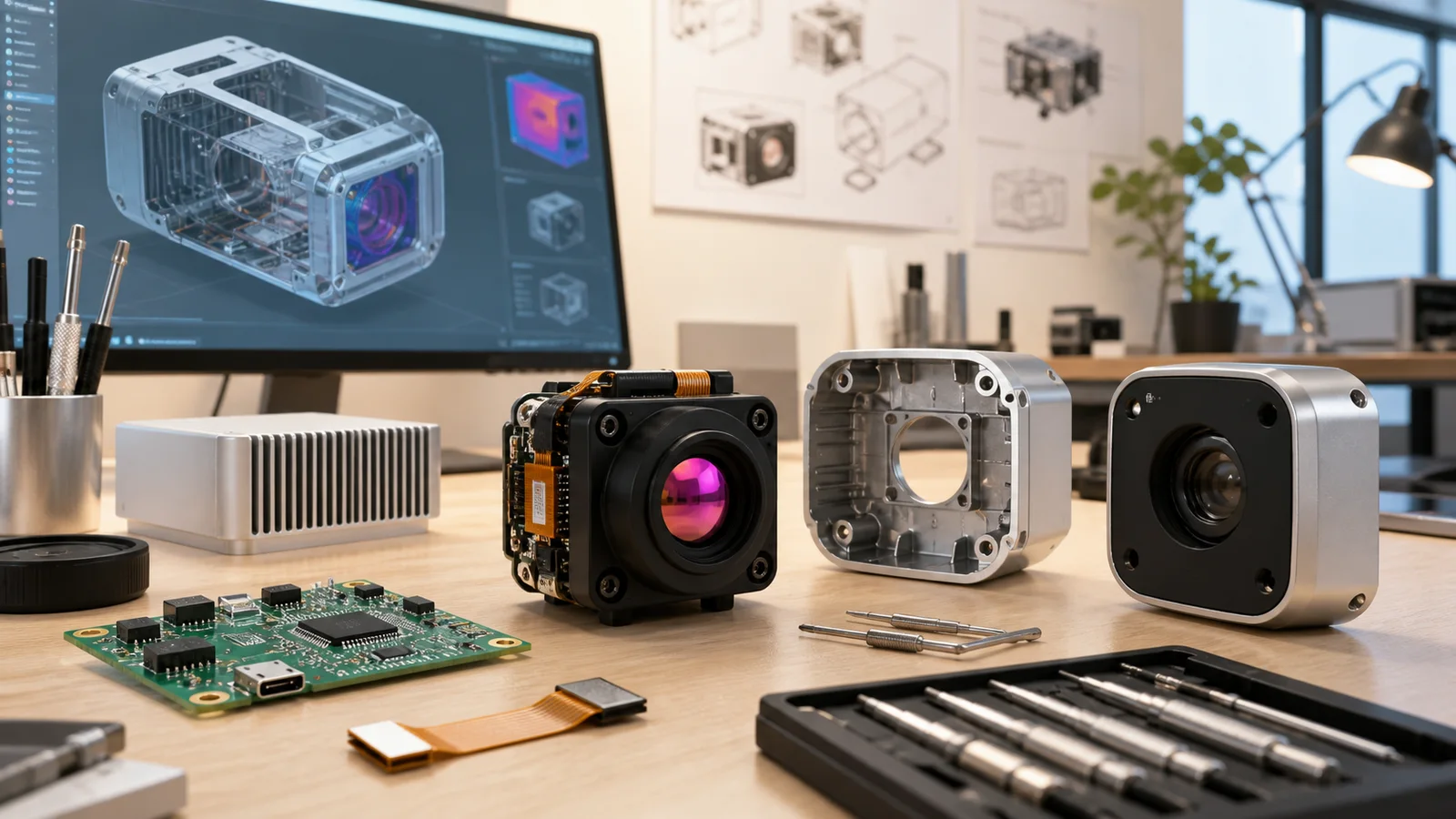
Mass directly governs the inertia and center of gravity (CoG) of 2-axis and 3-axis brushless gimbals. In aerial thermography, maintaining image stability is paramount, especially when working with high optical magnification or narrow instantaneous fields of view (IFOV). Gimbal stabilization systems must continuously counteract angular jitter, wind gusts, and airframe vibrations to keep angular pointing error below half of the sensor’s pixel projection:
Angular Error ≤ IFOV / 2
When engineering a payload, module mass divides the hardware landscape into two key operational classes:
- ⚙️ Micro-Cores (20 g to 30 g range): Modules such as the 23.1 g class allow system architects to deploy compact, direct-drive brushless gimbals equipped with lightweight motors (such as 2204-size or 2208-size). These motors consume less than 1.5 to 2.0 W of continuous power during stabilization, significantly preserving the main flight battery while keeping the overall takeoff mass below critical regulatory thresholds (such as the FAA / EASA 249-gram category).
- ⚙️ High-Resolution / Long-Range Cores (60 g to 100 g range): Megapixel sensors require sturdier carbon-fiber gimbal cages, precision counterweights, and higher-torque motors. While adding mass, they deliver the structural stability necessary to carry heavy multi-element Germanium optics without inducing mechanical resonance during high-speed forward flight.
Power Management and Parasitic Thermal Dissipation
Thermal camera cores integrated into UAVs must interface cleanly with erratic power rails, which can fluctuate from raw 2S LiPo voltages (6.0 V to 8.4 V) up to 6S or 12S industrial battery buses (22.2 V to 50.4 V). Utilizing thermal cores equipped with wide-input internal switching regulators (e.g., 5–24 V DC) reduces the requirement for external voltage regulation circuitry, trimming auxiliary wiring and point-of-load converter mass.
Uncooled microbolometers are exceptionally sensitive to thermal gradients within the gimbal shell. An inefficient onboard power supply that dissipates excessive heat (e.g., >2 W) inside a sealed enclosure introduces non-uniform temperature profiles across the focal-plane array (FPA). This induced thermal drift degrades measurement accuracy and forces frequent Non-Uniformity Correction (NUC) shutter events. Selecting modules that maintain reference power consumptions below 0.7 W ensures minimal self-heating, allowing passive conductive dissipation through the gimbal chassis without requiring heavy active cooling fans.
2. Uncooled Microbolometer Sensor Architecture: Resolution vs. Pixel Pitch
At the center of an airborne thermal system is the uncooled Vanadium Oxide (VOx) microbolometer focal-plane array. Unlike photon detectors that require bulky cryocoolers (such as InSb or MCT detectors operating at 77 Kelvin), VOx microbolometers detect electromagnetic radiation in the Long-Wave Infrared (LWIR) atmospheric transmission window (8 to 14 μm) by measuring the temperature-induced change in electrical resistance across micro-machined bridge pixels suspended over a silicon Readout Integrated Circuit (ROIC).
Pixel Pitch Dynamics: 12 μm vs. Legacy 17 μm Arrays
Modern aerial thermal imaging has transitioned from legacy 17 μm detector designs to advanced 12 μm fabrication nodes. Reducing the pixel pitch from 17 μm to 12 μm delivers direct mechanical and optical benefits for UAV integration:
- ✅ Reduced Focal Length for Equivalent Optical Magnification: For a given field of view, a 12 μm sensor requires a lens with an optical focal length that is approximately 30% shorter than that needed by a 17 μm sensor. Because optical mass scales cubically with aperture diameter and focal length, this reduction significantly shrinks the mass and volume of expensive Germanium or Chalcogenide optical elements.
- ✅ Smaller Sensor Footprint: The physical dimensions of a 640×512 array on a 12 μm pitch measure only 7.68 mm × 6.14 mm (diagonal ~9.83 mm), compared to 10.88 mm × 8.70 mm for a 17 μm array. This compact active area enables ultra-compact housing designs measuring 35 × 35 × 35 mm or smaller.
- ✅ Lower Aerodynamic Drag: Smaller optical front elements minimize aerodynamic drag on high-speed fixed-wing and VTOL airframes, extending line-of-sight range and battery endurance.
Thermal Sensitivity: Noise Equivalent Temperature Difference (NETD)
Thermal sensitivity is quantified by Noise Equivalent Temperature Difference (NETD), expressed in milliKelvins (mK). NETD represents the temperature difference that produces a signal-to-noise ratio (SNR) of unity at the detector output. In aerial applications, atmospheric moisture, ground dust, and high flight altitudes attenuate infrared radiation, lowering target thermal contrast.
Sensors with an NETD of ≤30 mK to ≤35 mK (tested at 25°C with an F/1.0 aperture) provide the contrast resolution needed to distinguish micro-thermal anomalies. This performance is vital in challenging industrial and search operations, including identifying subsurface delamination in wind turbine blades, pinpointing loose terminal connections in high-voltage transmission towers, detecting moisture ingress under roofing membranes, and locating lost hikers in dense forest canopies. For broader context on infrared thermography standards and industrial methodologies, review Wikipedia’s reference on thermography, or consult the sensor architectures provided by CAMCUDA OEM thermal imaging solutions.
3. Thermal Optics Selection, IFOV Calculations, and Johnson’s Criteria
Matching the lens focal length to the operational flight profile is critical when designing an infrared camera drone. An improper optical selection results in either insufficient ground coverage (field of view too narrow) or an inability to resolve targets at safe standoff altitudes (instantaneous field of view too coarse).
Instantaneous Field of View (IFOV) and Ground Resolution
The Instantaneous Field of View (IFOV) defines the angular spatial resolution of a single detector pixel projected through the optical train into object space, calculated as:
IFOV (mrad) = Pixel Pitch (p) / Focal Length (f) = 12 μm / f (mm)
The resulting spatial spot size or Ground Sample Distance (GSD) at a slant range or flight altitude D is:
Spot Size (S) = D × IFOV
For instance, pairing a 12 μm pixel detector with a 9.1 mm focal length lens yields:
IFOV = 12 μm / 9.1 mm ≈ 1.318 mrad
At a flight altitude of 100 meters, each pixel covers a ground footprint of 13.18 cm × 13.18 cm. Stepping up to a 35 mm lens narrows the IFOV to 0.34 mrad, resolving a tight 3.4 cm ground footprint from the exact same 100-meter standoff distance.
Empirical Range Calculations: Johnson’s Criteria
Thermal target acquisition is modeled using Johnson’s Criteria, which calculates the number of resolved line pairs (or pixel cycles) required across a target’s critical dimension for Detection, Recognition, and Identification (DRI). For a standard human target profile (1.8 m × 0.5 m with a 0.75 m critical dimension):
- 🎯 Detection (2 pixels across critical dimension): The operator can distinguish that an object is present in the scene against the thermal background.
- 🎯 Recognition (8 pixels across critical dimension): The operator can determine the class of the target (e.g., distinguishing a human from a quadruped animal or a light vehicle).
- 🎯 Identification (12.8 pixels across critical dimension): The operator can discern specific features (e.g., identifying clothing type, tools carried, or specific vehicle classifications).
The table below summarizes standard DRI distance estimations across various factory-installed focal lengths using a 12 μm VOx sensor:
| Focal Length | Horizontal × Vertical FOV | IFOV (Spatial Resolution) | Human Detection (2 px) | Human Recognition (8 px) | Human Identification (12.8 px) |
|---|---|---|---|---|---|
| 4.1 mm | Extra-Wide Angle | ~2.92 mrad | ~398 m | ~99 m | ~50 m |
| 4.9 mm | 76.2° × 64.2° | 2.45 mrad | 476.0 m | 119.0 m | 60.0 m |
| 9.1 mm | 45.8° × 37.3° | 1.31 mrad | 884.7 m | 221.2 m | 110.6 m |
| 13.0 mm | 33.0° × 26.6° | 0.92 mrad | 1,263.9 m | 316.0 m | 158.0 m |
| 19.0 mm | 22.9° × 18.4° | 0.63 mrad | 1,847.2 m | 461.8 m | 230.9 m |
| 35.0 mm | 12.5° × 10.0° | 0.34 mrad | 3,402.8 m | 850.7 m | 425.4 m |
4. Data Interface & Protocol Engineering: CVBS, UVC, MIPI, and Digital Streams
Connecting the LWIR core to the drone’s avionics, gimbal slip-rings, and edge-compute processors requires selecting the right electrical interface. Look, your choice of interface directly dictates system latency, computational overhead, and whether you can extract true per-pixel radiometric temperature data in real time.
1. CVBS (Composite Video Baseband Signal – Analog)
Analog CVBS video (PAL or NTSC) remains a primary standard for piloting and low-latency First-Person View (FPV) flight. With an inherent latency of under 20 ms, the raw video feed routes straight from the core into 5.8 GHz analog video transmitters without incurring frame buffer compression delays. This near-zero latency gives manual pilots responsive visual feedback when flying close to transmission lines, tree lines, or structural obstacles during close-quarters SAR flights. However, CVBS output is strictly limited to standard analog display resolutions and cannot transport digital per-pixel temperature matrices across the physical cable.
2. USB UVC (Universal Video Class)
USB UVC offers standardized digital plug-and-play capability with embedded Linux companion computers (such as NVIDIA Jetson Orin Nano, Raspberry Pi Compute Module 4, or Rockchip SBCs). Operating through standard Video4Linux2 (V4L2) kernel drivers, UVC interfaces enable developers to ingest 50 Hz thermal video streams and extract 14-bit or 16-bit radiometric metadata without writing custom low-level device drivers, accelerating time-to-market for custom payload builds.
3. MIPI CSI-2 & BT.656 / BT.1120 Parallel Digital Buses
For advanced deep-learning vision pipelines (such as real-time onboard human/vehicle target tracking via YOLO or custom CNNs), MIPI CSI-2 and BT.1120 parallel buses provide high-speed, direct memory access (DMA) into the host processor’s Image Signal Processor (ISP). This direct bus architecture eliminates USB host controller bottlenecks, minimizes CPU overhead, and delivers full-frame 14-bit/16-bit radiometric depth at 50 Hz with sub-frame transmission latency.
4. SDI & CameraLink Industrial Digital Standards
For high-definition payloads and defense-grade gimbals, interfaces such as HD-SDI and CameraLink route uncompressed digital video through multi-channel slip-rings into high-bandwidth COFDM or tactical IP datalinks. These standards provide robust EMI immunity against high electrical noise generated by powerful drone ESCs, motor phase leads, and telemetry radios.
5. Custom Thermal Payloads vs. Locked Commercial Drone Ecosystems
Engineering departments often face a build-versus-buy decision: procure a commercial-off-the-shelf (COTS) turnkey enterprise drone or engineer a custom modular payload around an OEM thermal core. Turnkey systems offer quick initial flights, but they present major operational and architectural bottlenecks down the line.
The Architectural Limitations of Locked Platforms
- ⚙️ Software and API Restrictions: Turnkey enterprise platforms often lock raw radiometric streams inside proprietary encrypted containers. This forces teams to rely on vendor cloud platforms or restricted mobile SDKs that prevent low-latency edge AI integration.
- ⚙️ Fixed, Inflexible Optical Configurations: Most commercial enterprise drones feature fixed wide-angle thermal lenses (typically 9 mm to 13 mm equivalent). They cannot be swapped for telephoto optics (such as 35 mm, 50 mm, or 100 mm), making safe, high-altitude standoff inspection impossible.
- ⚙️ High Unit Bill of Materials (BOM) & Replacement Costs: When deploying drone fleets, proprietary replacement payloads cost thousands of dollars per unit. Building around OEM cores cuts payload BOM costs by 40% to 60%, drastically reducing fleet maintenance overhead.
- ⚙️ Regulatory & Supply Chain Compliance: Institutional, utility, and defense contractors increasingly require strict supply chain transparency and NDAA compliance. Developing an in-house payload with an open OEM module ensures hardware traceability and eliminates unauthorized backchannel data transmission risks.
6. Technical Evaluation: CAMCUDA FlexMini 640 vs. HR-1280
To support diverse payload requirements, CAMCUDA offers two distinct OEM uncooled LWIR thermal imaging platforms: the ultra-lightweight, low-power CAMCUDA FlexMini 640 and the high-definition megapixel CAMCUDA HR-1280.
Product Showcase: CAMCUDA FlexMini 640 LWIR Thermal Camera Module
The CAMCUDA FlexMini 640 is an ultra-compact, high-performance OEM thermal core engineered for lightweight UAV gimbals, sub-250g drone builds, and SWaP-constrained industrial payloads. Featuring an uncooled VOx 640×512 focal plane array with a 12 μm pixel pitch and an exceptional thermal sensitivity rating (≤30 mK reference NETD), the CAMCUDA FlexMini 640 delivers sharp, high-contrast imagery at a smooth 50 Hz frame rate. Weighing only 23.1 grams and consuming less than 0.7 W of power, it preserves precious battery capacity and enables extended flight endurance.
Key Technical Specifications
| Detector Array | Uncooled VOx Focal-Plane Array |
|---|---|
| Resolution | 640 × 512 pixels |
| Pixel Pitch | 12 μm |
| Spectral Response | 8 – 14 μm (LWIR) |
| Thermal Sensitivity (NETD) | ≤30 mK reference (@25°C, F/1.0) |
| Frame Rate | 50 Hz |
| Power Consumption | <0.7 W reference consumption |
| Input Voltage | 5 – 24 V DC wide-voltage input |
| Video Output Options | CVBS (Analog, <20 ms latency), USB UVC, or MIPI |
| Module Weight | 23.1 g |
| Operating Temperature | -20°C to +60°C |
| Factory-Installed Optics | 4.1 mm, 4.9 mm ($518.31), 9.1 mm ($423.10), 13 mm, 19 mm, 35 mm |
The factory-fitted lens design ensures optical alignment and structural rigidity in high-vibration drone environments. The rear-interface configuration supports both rapid FPV piloting via CVBS analog pins and direct AI edge compute integration via USB UVC and MIPI.
Product Showcase: CAMCUDA HR-1280 High-Resolution LWIR Thermal Camera Module
The CAMCUDA HR-1280 is a high-definition 1280×1024 uncooled VOx thermal imaging core designed for advanced UAV payloads, long-range aerial surveillance, border patrol, and high-precision infrastructure thermography. Packing over 1.3 million active thermal pixels on a 12 μm pitch with ≤35 mK sensitivity, it delivers four times the spatial resolution of standard 640×512 sensors. This allows inspection drones to identify millimeter-scale structural defects and capture detailed thermographic maps from safe standoff distances.
Key Technical Specifications
| Detector Array | Uncooled VOx Microbolometer |
|---|---|
| Resolution | 1280 × 1024 pixels (Megapixel HD Thermal) |
| Pixel Pitch | 12 μm |
| Spectral Band | 8 – 14 μm (LWIR) |
| Thermal Sensitivity (NETD) | ≤35 mK @25°C, F#1.0 |
| Frame Rate | 50 Hz |
| Input Operating Voltage | 5 – 24 V DC |
| Digital Video Output | BT656 / BT1120 / SDI / CameraLink (No CVBS) |
| Serial Control Bus | RS232 / RS485 / RS422 |
| Bare Module Mass | 68 g (without lens) |
| Physical Dimensions | 35 × 35 × 35 mm (without lens) |
| Interchangeable Lens Matching | 9 / 13 / 19 / 25 / 35 / 50 / 75 / 100 mm options |
| Compliance | NDAA statement available on request |
The HR-1280 is engineered for heavy-lift multirotor and fixed-wing tactical platforms requiring broad digital connectivity (BT1120, SDI, CameraLink) and long-range telephoto lens matching (up to 100 mm optics) for stand-off target tracking and large-scale industrial photogrammetry.
7. Step-by-Step Payload Integration & NUC Calibration Checklist
Successfully integrating an uncooled thermal imaging core into an airborne UAV gimbal requires careful mechanical, electrical, optical, and software engineering. Follow this structured checklist to ensure mission-ready performance:
Phase 1: Mechanical Mount & Optical Co-Axial Alignment
- ⚙️ Static Mechanical Balancing: Mount the thermal core and lens within the gimbal inner yoke. Adjust the physical center of gravity (CoG) along the pitch and roll axes until the payload stays neutrally balanced with gimbal motor power turned completely off. This reduces motor heating and avoids stabilization jitter during high-G flight maneuvers.
- ⚙️ Multi-Sensor Co-Axial Boresighting: When pairing the thermal core alongside an electro-optical (EO) visible zoom camera or laser rangefinder (LRF), align their optical axes using an optical collimator or a distant terrestrial thermal reference target to ensure synchronized dual-sensor tracking.
- ⚙️ Vibration Isolation: Isolate the payload gimbal assembly using tuned silicone damping balls (durometer 30A to 50A) matched to the airframe’s dominant motor and propeller harmonic frequencies (typically 80 Hz to 200 Hz).
Phase 2: Electrical Wiring, Ground Isolation & EMI Shielding
- ⚙️ Clean Power Distribution: Power the thermal core using an isolated DC-DC step-down buck regulator fed directly from the main power distribution board. Place ferrite chokes and low-ESR ceramic capacitors on the 5–24 V DC power input lines to filter out switching noise from Electronic Speed Controllers (ESCs).
- ⚙️ Ground Loops: Maintain a star-ground configuration between the thermal core, gimbal controller, companion SBC, and video transmitter to eliminate ground loops that cause horizontal noise banding across analog CVBS video feeds.
- ⚙️ High-Flex Slip-Ring Wiring: Route digital video lines (MIPI CSI-2, USB, or SDI) through high-speed, shielded miniature slip-rings to prevent signal degradation and eliminate mechanical cable wrapping during continuous 360-degree yaw rotation.
Phase 3: Serial Communication & Telemetry Control
- ⚙️ Baud Rate & Command Setup: Configure UART / RS232 / RS485 communication lines between the flight companion computer and the thermal module. Implement standard telemetry commands for digital zoom, thermal color palette selection (e.g., White Hot, Black Hot, Ironbow, Rainbow), and radiometric temperature thresholds.
- ⚙️ Raw Radiometric Stream Handling: If using USB UVC or MIPI buses, ensure the host operating system kernel handles 14-bit/16-bit uncompressed Y16 pixel formats cleanly, routing raw pixel streams directly to GPU memory for real-time edge processing.
Phase 4: Non-Uniformity Correction (NUC) & Dynamic Shutter Management
Because uncooled microbolometers drift as ambient temperatures fluctuate during flight (e.g., climbing through cool thermal inversion layers), the sensor must execute Non-Uniformity Correction (NUC) using an internal mechanical shutter or an advanced shutterless calibration algorithm.
- ⚙️ Pre-Flight Warm-Up NUC: Allow the thermal module to run for 3 to 5 minutes prior to takeoff. During this initial thermal stabilization phase, configure the internal shutter to cycle every 60 to 90 seconds.
- ⚙️ In-Flight Shutter Management: In fast-moving tracking scenarios or automated waypoint mapping missions, an unexpected mechanical shutter click freezes the video stream for 200–500 ms, which can disrupt real-time computer vision tracking. Configure the core’s control firmware to execute NUC based on ambient temperature delta triggers (ΔT ≥ 1.5°C) or initiate calibration sweeps via companion software commands during non-critical flight legs.
8. Frequently Asked Questions (FAQ)
Why should engineering teams integrate an OEM thermal module instead of buying a locked commercial enterprise infrared camera drone?
What video interfaces and protocols are best suited for UAV thermal camera integration?
How do lens focal length and IFOV affect drone inspection and target detection ranges?
📚 References & Further Reading
- Industry Standard: Wikipedia – Microbolometer Sensor Overview
- Industry Standard: Wikipedia – Infrared Thermography Principles
- Related Guide: CAMCUDA Technical Downloads & Interface Documentation
- Product Overview: CAMCUDA OEM Thermal Imaging Solutions
- Engineering Support: Submit an Integration RFQ & Technical Consultation Request