Drones with Infrared Cameras: OEM Thermal Module Selection Guide
Drones with Infrared Cameras: OEM Thermal Module Selection Guide
Building drones with infrared cameras requires balancing Size, Weight, Power, and Cost (SWaP-C) against the mission. Public-safety search, utility inspection and agricultural surveys place different demands on optical detail, thermal sensitivity and onboard processing. When an enclosed commercial camera is too heavy or lacks the required interface, an embedded OEM long-wave infrared (LWIR) module offers another integration path. Evaluate the complete payload, including optics, interface boards, cabling, power conversion and enclosure, rather than comparing bare-core figures alone.
A mission-ready thermal payload needs more than a sensor attached to an airframe. For the modules compared here, integration combines an uncooled Vanadium Oxide (VOx) focal plane array, suitable pixel pitch and optics, a low-latency video pipeline, and a validated thermal and mechanical package. This guide compares the featured AeroMini 640 with SuperMini 640 / 640T. The main AeroMini reference is the 9 mm non-radiometric configuration; SuperMini imaging and thermographic models are treated separately.
Table of Contents
- 👉 1. Thermal Imaging Fundamentals for Aerial Platforms
- 👉 2. SWaP-C Optimization: Core Mass, Pixel Pitch, and Thermal Envelopes
- 👉 3. Digital Video Pipelines, Electrical Interfaces, and Low Latency
- 👉 4. Optics Selection and Johnson Criteria DRI Calculations
- 👉 5. OEM Thermal Core Benchmark: CAMCUDA SuperMini 640 / 640T vs. CAMCUDA AeroMini 640
- 👉 6. Radiometric Temperature Measurement vs. High-Frame-Rate Imaging
- 👉 7. Power Delivery, Thermal Dissipation, and Mechanical Integration
- 👉 8. Frequently Asked Questions (FAQ)
1. Thermal Imaging Fundamentals for Aerial Platforms
The modules compared here operate in the 8–14 µm LWIR band. Unlike visible cameras, they can show thermal contrast without visible illumination. The Stefan–Boltzmann relation, j* = εσT4, describes total emitted power per unit area: ε is emissivity, σ the Stefan–Boltzmann constant and T absolute temperature in kelvin. A thermal camera measures a limited spectral band, including emitted and reflected radiance modified by the atmosphere. Fog, rain, vegetation and smoke can reduce useful contrast or obscure targets; thermal imaging does not guarantee visibility through them.
An uncooled microbolometer focal plane array (FPA) absorbs LWIR radiation on thermally isolated elements above a silicon Readout Integrated Circuit (ROIC). The absorbed energy changes the sensing material’s resistance. VOx and amorphous-silicon microbolometers are both used in thermal imaging; the modules discussed here use VOx. Compare the complete detector, optics, readout and processing through published NETD, temporal response, frame rate and power. Material choice alone does not establish a universal noise or response-time advantage.
Thermal sensitivity is commonly expressed as Noise Equivalent Temperature Difference (NETD), in millikelvins (mK). It is the scene-temperature difference that produces a signal equal to the RMS output noise under specified measurement conditions:
NETD (K) ≈ σsignal / |∂S/∂T|; NETD (mK) = 1000 × NETD (K)
Here, σsignal is RMS output noise and ∂S/∂T is the measured signal change per kelvin of scene temperature. Compare the same optics, target temperature, bandwidth and processing settings. AeroMini publishes NETD ≤30 mK and SuperMini ≤40 mK, both at 25 °C and F1.0. Lower NETD can help reveal weaker thermal contrast under comparable conditions, but it does not by itself establish detection range. Optical throughput, detector/readout design and processing also affect useful image detail.
Pixel-to-pixel response differences and temperature drift can create fixed-pattern noise (FPN). Non-Uniformity Correction (NUC) compensates for these differences. Shutter-based and scene-based correction are approaches used in thermal imaging, but supported methods and controls depend on the module and firmware. Shutter correction may briefly hold the image. AeroMini provides supported NUC/FFC settings, including automatic triggering behavior, through its PC software. Validate warm-up, airflow changes and representative motion before flight; do not assume either family offers arbitrary shutterless controls or uninterrupted output.
2. SWaP-C Optimization: Core Mass, Pixel Pitch, and Thermal Envelopes
Size, Weight, Power, and Cost (SWaP-C) shape payload design. Added mass changes thrust requirements, balance and power demand. Its effect on endurance depends on the airframe, propulsion system, battery and flight profile.
For a sub-500 g platform, evaluate an additional 50 g in the complete mass, center-of-gravity and propulsion budget, then measure endurance and motor temperature under the intended flight profile. Sensor volume and balance also affect gimbal motor sizing, bearing loads and housing drag. Bare-core mass excludes hardware that can dominate the finished payload.
Moving from 12 µm to 8 µm pixel pitch can reduce the focal length needed for the same array resolution and angular coverage. That change brings useful design opportunities, with limits:
- ✅ Optics Miniaturization: For a fixed array resolution and FOV in the same projection, focal length f scales with pixel pitch d. The ratio 8/12 = 2/3 means a 33.3% shorter focal length. At fixed f-number, the entrance pupil also becomes smaller. Lens mass has no universal cubic scaling rule: element thickness, material, lens count, distortion correction and mounting design all matter.
- ✅ Gimbal Inertia and Dynamic Response: The point-mass relation I = mr2 illustrates how mass m and distance r from the rotation axis affect inertia. A real payload has distributed mass. Choose gimbal motors and their current budget using the full assembly and measured dynamic load, rather than assuming a smaller core guarantees a particular current saving.
- ✅ Thermal Dissipation Budgets: Low core power helps, but the enclosure and electronics still need a validated heat path. SuperMini publishes ≤0.5 W typical core power at 25 °C, excluding the expansion board. AeroMini publishes <0.5 W typical module power at 25 °C. Check the complete-kit load and thermal gradients; these figures do not establish cooling sufficiency.
If you are planning a fresh multi-spectral or thermal airframe build, take a spin through our infrared camera module OEM buying guide for deep-dive hardware selection rules.
3. Digital Video Pipelines, Electrical Interfaces, and Low Latency
Aerial integration needs a defined latency budget and a video format the host can receive. Pilot displays and onboard vision impose different requirements on capture, buffering, processing and transmission. Measure the whole pipeline under representative load. Neither interface bandwidth nor nominal frame rate alone establishes end-to-end delay.
OEM modules offer configuration-dependent digital and analog paths. Match each path to the delivered board, firmware, receiver and operating system:
- ⚙️ MIPI CSI-2: SuperMini specifies a 2-lane path. A compatible receiver and driver must accept the selected camera format over the MIPI D-PHY physical link. Hardware DMA can reduce copying on a supported host, but does not establish sensor-to-memory latency. Confirm lane timing, packing, buffers and delivered frame rate. Standard AeroMini output is not RAW/minimally processed video; MIPI availability does not change that boundary.
- ⚙️ 8-Bit LVCMOS / Parallel BT.656: Match clocking, signal voltage, synchronization and pixel packing to the receiver. SuperMini documents 8-bit LVCMOS/BT656 paths and a separate 640T CDS3 format. These labels do not establish one interchangeable timing scheme or a standard-definition stream for every mode. Check the model-specific manual and actual firmware timing before PCB or FPGA implementation.
- ⚙️ USB UVC (Universal Video Class): UVC can simplify evaluation when the device mode and host stack match. Confirm pixel format, resolution, frame rate and controls in the intended operating system. The AeroMini documentation folder lists USB manuals, PC software and USB-SDK.zip; the product FAQ describes Linux drivers, examples and SDK resources there. These are AeroMini resources, not proof of SuperMini compatibility. Measure capture, processing and display delay on the finished pipeline.
- ⚙️ Analog CVBS (Composite Video): CVBS supports compatible analog capture, display or radio equipment. It does not carry the calibrated per-pixel temperature words discussed below. Latency depends on the complete camera, radio and display chain. SuperMini’s core CVBS pin requires an external video-buffer IC; AeroMini buffering and wiring depend on the selected board. Verify signal integrity with the actual harness and moving assembly.
| Interface protocol | Latency validation | Host workload | Typical integration task |
|---|---|---|---|
| MIPI CSI-2 (SuperMini: 2 lanes) | Measure sensor-to-host and full display delay | Receiver/driver/DMA and buffer-path dependent | Embedded capture and onboard vision with a matched host |
| 8-bit parallel / BT656 | Measure the configured clock, buffering and receiver path | FPGA or capture-controller implementation dependent | Custom parallel capture or video-encoder integration |
| USB 2.0 UVC | Measure the delivered mode on the chosen OS | UVC stack, copying and processing dependent | Evaluation and host-supported USB capture |
| Analog CVBS | Measure the camera, radio/capture and display chain | Capture/encoding/display implementation dependent | Compatible analog video equipment; no calibrated temperature words |
4. Optics Selection and Johnson Criteria DRI Calculations
Lens selection balances Field of View (FOV) against the number of samples across a distant feature. Wide coverage may suit surveying and broad-area search; a narrower lens can place more pixels across a distant inspection target. This trade-off must also account for distortion, optical sharpness, stabilization and the actual target orientation.
The Instantaneous Field of View (IFOV) approximates the near-axis angular pitch of one detector sample. It is a useful sampling estimate, rather than a complete measure of optical resolving power:
IFOV (mrad) ≈ d (µm) / f (mm)
Here, d is pixel pitch in micrometers and f is focal length in millimeters. A smaller nominal IFOV puts more samples across the same distant feature. Lens modulation transfer, diffraction, distortion and sampling still affect resolved detail. Use the manufacturer’s published optical FOV; do not replace it with a simple pinhole estimate.
Johnson criteria provide historical observer-based reference thresholds for detection, recognition and identification. A published discussion of the criteria gives nominal 50% observer thresholds of about 1, 4 and 6.4 line pairs across a critical target dimension. One line pair corresponds to two sampled pixels in this simplified planning convention:
- ⚙️ Detection reference: 1 line pair / 2 pixels. A nominal threshold for noticing that an object is present.
- ⚙️ Recognition reference: 4 line pairs / 8 pixels. A nominal threshold for recognizing the broad target class.
- ⚙️ Identification reference: 6.4 line pairs / 12.8 pixels. A nominal threshold for distinguishing more specific target characteristics.
For the illustrative calculations below, choose a critical target dimension Hc = 0.75 m. This is an explicit example input, not an asserted standard human dimension. The geometry-only range R for a specified number of pixels across that feature is:
R (m) ≈ 1000 × Hc (m) × f (mm) / [Npixels × d (µm)]
Npixels is the chosen sample count across Hc; the factor 1000 accounts for the mm/µm units. These calculated ranges are not empirical results or predictions of a particular human-observer success probability. Atmosphere, thermal contrast, optics, stabilization, processing, NUC and viewing conditions remain outside this calculation. Explore different assumptions with the thermal imaging calculator, checking its presets because they may differ from this example. For environmental limitations, see outdoor field thermal imaging.
5. OEM Thermal Core Benchmark: CAMCUDA SuperMini 640 / 640T vs. CAMCUDA AeroMini 640
Match electrical interfaces and mechanical constraints to the platform’s operating profile. The comparison below covers two current featured OEM LWIR families: AeroMini 640, using its 9 mm non-radiometric configuration as the main reference, and the separate SuperMini 640 imaging / 640T thermographic models. Confirm the complete delivered configuration before committing the payload design.
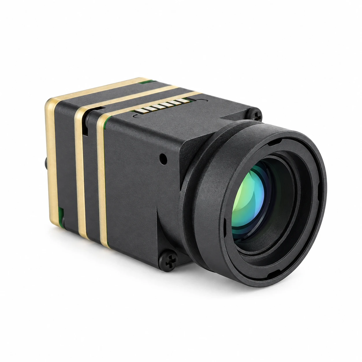
Product Showcase: CAMCUDA SuperMini 640 / 640T
640 × 512 | 8 µm Pixel Pitch | <3.5 g Core, Excluding Optics and Boards | ≤0.5 W Typical Core Power at 25 °C
CAMCUDA SuperMini 640 / 640T uses a 640 × 512, 8 µm VOx detector. The 13 × 13 × 13.4 mm dimensions and <3.5 g mass exclude optics and expansion boards; ≤0.5 W is typical core power at 25 °C, excluding the expansion board. SuperMini 640 provides 50 Hz imaging. SuperMini 640T provides 30 Hz thermography over model-specific CDS3 or MIPI paths, with ranges of −20 °C to +150 °C and 100 °C to +650 °C. The photo is a lens-equipped family appearance reference. Lens, interface and supplied items require configuration review and quotation.
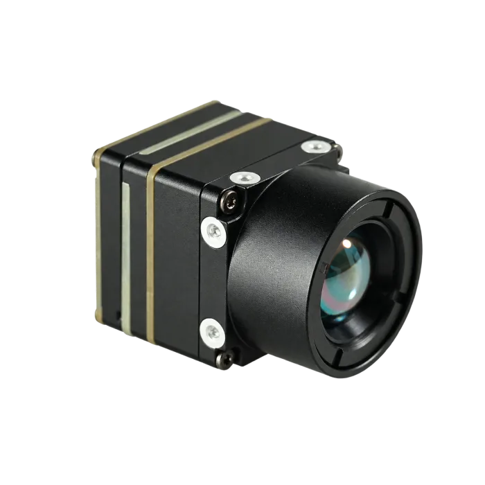
Product Showcase: CAMCUDA AeroMini 640 · 9 mm
640 × 512 | 12 µm Pixel Pitch | ≤30 mK NETD at 25 °C, F1.0 | 60 Hz Default / 30 Hz Factory Option
CAMCUDA AeroMini 640 uses a 640 × 512, 12 µm VOx detector. The 9 mm non-radiometric reference has a published 48.7° × 38.6° FOV, 60 Hz factory default and an optional 30 Hz factory configuration at the same price. Typical module consumption is <0.5 W at 25 °C. The <20 g mass and 21 × 21 × 28 mm dimensions exclude lens and flange. Choose the USB + CVBS + MIPI or Type-C + CVBS tailboard for the intended host; confirm the complete assembly and delivered output mode. Standard output is not RAW/minimally processed video.
For procurement specifications and volume RFQ parameters, check our thermal camera suppliers OEM RFQ checklist.
Comprehensive Engineering Specifications Comparison
| Specification parameter | CAMCUDA SuperMini 640 / 640T | CAMCUDA AeroMini 640 · 9 mm non-radiometric reference |
|---|---|---|
| Detector array type | Uncooled VOx microbolometer FPA | Uncooled VOx microbolometer FPA |
| Array resolution | 640 × 512 pixels | 640 × 512 pixels |
| Pixel pitch | 8 µm | 12 µm |
| Spectral range | 8–14 µm (LWIR) | 8–14 µm (LWIR) |
| Thermal sensitivity (NETD) | ≤40 mK at 25 °C, F1.0 | ≤30 mK at 25 °C, F1.0 |
| Reference dimensions | 13 × 13 × 13.4 mm; core only, excluding optics and boards | 21 × 21 × 28 mm; excluding lens and flange |
| Reference mass | <3.5 g; core only, excluding optics and boards | <20 g; excluding lens and flange |
| Frame refresh rate | 640 imaging: 50 Hz; 640T thermographic: 30 Hz | Non-radiometric: 60 Hz default / 30 Hz factory option |
| Power consumption | ≤0.5 W typical core power at 25 °C, excluding expansion board | <0.5 W typical module power at 25 °C; verify complete-kit budget |
| Supply voltage input | MAIN_POWER 3.8–5.2 V plus 3.28–3.32 V and 1.78–1.82 V rails; follow startup timing | Board dependent; illustrated POWER_IN1/POWER_IN2 are 5 V only, never 12 V |
| Video outputs | Model-specific 8-bit LVCMOS/BT656, 640T CDS3 and 2-lane MIPI; BT656/MIPI not simultaneous | USB + CVBS + MIPI or Type-C + CVBS package; confirm board/firmware/host mode |
| Electrical connector | Hirose DF40C-30DP-0.4V(51), 30-pin bare-core interface | Illustrated 16-pin USB/CVBS and 26-pin MIPI/DVP references; Type-C uses its matched guide |
| Temperature measurement | 640: none; 640T: −20…+150 °C / 100…+650 °C; typical ±2 °C or ±2% at ambient −20…+60 °C | None in this non-radiometric reference; separate 25 Hz radiometric version is currently enquiry-only |
Optical Assembly Options & Illustrative DRI Calculations
CAMCUDA SuperMini 640 / 640T Athermal Lens Lineup (8 µm Pitch)
The current SuperMini product page lists these F1.0 athermal lens configurations. Their FOV and IFOV figures are published optical specifications. Validate focus and the complete assembly across the intended temperature and vibration conditions:
- ⚙️ 3.7 mm Focal Length: 90.0° × 68.2° FOV | 2.16 mrad IFOV (wide angular coverage; validate suitability for the mission).
- ⚙️ 6.1 mm Focal Length: 46.6° × 37.6° FOV | 1.31 mrad IFOV (broader-area observation; validate suitability for the mission).
- ⚙️ 8.7 mm Focal Length: 40.0° × 32.2° FOV | 0.92 mrad IFOV (more samples across a distant feature; validate suitability for the mission).
- ⚙️ 11.0 mm Focal Length: 24.9° × 20.0° FOV | 0.73 mrad IFOV (narrower angular coverage; validate suitability for the mission).
CAMCUDA AeroMini 640 Lens Examples & Calculated Sampling Ranges (12 µm Pitch)
The following five lens examples use the current AeroMini published FOV, d = 12 µm and the illustrative Hc = 0.75 m. IFOV and ranges are calculated from unrounded focal length and pitch; range columns use 2, 8 and 12.8 pixels. Values are geometry-only planning estimates, not tested human DRI or probability guarantees. Wide-angle edge sampling can differ from the nominal near-axis IFOV. Lens listings do not imply stock availability; confirm the exact non-radiometric assembly when ordering.
| AeroMini focal length | Published FOV H × V | Nominal IFOV | Range at 2 pixels | Range at 8 pixels | Range at 12.8 pixels |
|---|---|---|---|---|---|
| 4 mm | 100° × 82° | 3.00 mrad | 125.0 m | 31.3 m | 19.5 m |
| 9 mm | 48.7° × 38.6° | 1.33 mrad | 281.3 m | 70.3 m | 43.9 m |
| 13 mm | 31.9° × 25.7° | 0.92 mrad | 406.3 m | 101.6 m | 63.5 m |
| 25 mm | 17.5° × 14° | 0.48 mrad | 781.3 m | 195.3 m | 122.1 m |
| 35 mm | 12.5° × 10° | 0.34 mrad | 1,093.8 m | 273.4 m | 170.9 m |
6. Radiometric Temperature Measurement vs. High-Frame-Rate Imaging
Before locking in a core, you need to answer one critical architectural question: do you need qualitative visual contrast, or calibrated absolute temperature data?
High-Frame-Rate Imaging Cores (CAMCUDA SuperMini 640 & CAMCUDA AeroMini 640)
SuperMini 640 offers 50 Hz imaging; AeroMini non-radiometric offers a 60 Hz factory default or 30 Hz factory option. Higher frame rate can improve temporal sampling, but motion blur, judder and tearing also depend on detector response, integration time, processing, synchronization and display. Match the delivered format and settings to the host. SuperMini lists grayscale stretching, local contrast, temporal/spatial noise reduction and detail/edge enhancement. Standard AeroMini is not a RAW/minimally processed source. Test image quality and transport delay at the required aircraft motion and scene contrast.
Radiometric Cores (CAMCUDA SuperMini 640T)
Calibrated temperature data is needed when an inspection requires quantitative readings. Qualitative images can still help locate relative anomalies in electrical, solar or building surveys. Decide whether the task requires temperature measurement, then validate emissivity, reflected surroundings, atmospheric effects and the model’s supported measurement workflow.
The CAMCUDA SuperMini 640T supports ranges of −20 °C to +150 °C and 100 °C to +650 °C, with typical accuracy ±2 °C or ±2% of reading at ambient −20 °C to +60 °C. CDS3 carries YUV422 image data plus temperature data. Its MIPI path uses RAW8 packets that the host reassembles, low byte first, into 16-bit image and temperature words. RAW8 describes transport packing, not a generic raw-radiance stream. Appendix 2 of the model’s manual gives these temperature conversions:
SuperMini 640T ND mode: T (°C) = (TEMP + 7000) / 30 − 273.2
SuperMini 640T HD mode: T (°C) = (TEMP − 4600) / 10 − 273.2
TEMP is the decoded received temperature value. Use the actual configured ND or HD mode, as specified in the SuperMini 640T temperature-conversion appendix; do not infer it from the value’s magnitude. These formulas do not extend the calibrated ranges or apply to SuperMini 640 imaging or AeroMini. The 640T’s specified rate is 30 Hz; validate capture, word reconstruction, conversion and inspection motion on the selected host.
AeroMini’s separate 25 Hz radiometric version is currently out of stock and available for supply enquiry only, with documented 9/13/18 mm lenses. It is not the online-purchasable non-radiometric 9 mm reference used in this comparison. Confirm its accuracy, interface and data format independently.
7. Power Delivery, Thermal Dissipation, and Mechanical Integration
Clean power delivery and stable mounting are essential parts of a thermal payload. Validate electrical behavior with motors and transmitters active, then repeat image-quality checks across the intended temperature and vibration conditions.
Power Supply Filtering and Noise Rejection
Supply noise can degrade thermal-image quality and stability. Measure rail tolerances and noise at the module connector during startup, steady operation and motor-load changes. The table below applies only to SuperMini 640 / 640T bare cores. Consult the 30-pin connector orientation and signal table and power requirements; expansion boards can change the external supply interface.
| SuperMini bare-core electrical path | Published voltage specification | Published noise / integration requirement |
|---|---|---|
| MAIN_POWER | 3.8–5.2 V; typical 5.0 V | Maximum noise: 10 mV p-p at the core connector |
| +3.3 V rail | 3.28–3.32 V | Maximum noise: 10 mV p-p at the core connector |
| +1.8 V rail | 1.78–1.82 V | Maximum noise: 1 mV RMS over 1 Hz–50 kHz |
| UART control | 1.8 V logic | TX/RX are core-referenced; use appropriate level translation for non-compatible host logic |
Select regulators, decoupling and any filters to meet the chosen module’s limits at the connector. Validate noise and transient behavior under actual motor and transmitter loads. For SuperMini, follow the manual’s t1/t2/t3 startup timing definitions, with each interval >200 µs. A universal LC/LDO topology or fixed regulator PSRR figure cannot establish compliance.
For AeroMini, use the current board-specific integration references: the illustrated 16-pin USB/CVBS and 26-pin MIPI/DVP POWER_IN1/POWER_IN2 pins are 5 V inputs, never 12 V. Their diagrams are electrical pinouts, not physical mating-view drawings. They do not apply to the Type-C board or SuperMini. The Type-C package needs its matched wiring guide; verify connector orientation, serial levels and supplied board revision before power-up.
Mechanical Mounting and Thermal Conduction
SuperMini 640 / 640T publishes ≤0.5 W typical core consumption at 25 °C, excluding the expansion board. The small core footprint concentrates that heat; boards and other payload electronics add to the enclosure load. Apply the following checks to the actual lens, carrier and housing assembly:
- ⚙️ Conductive Heat Path: Provide a controlled heat path through approved mounting surfaces. Validate enclosure temperature, thermal gradients and warm-up stability. Interface-material conductivity alone does not establish the finished thermal resistance; avoid applying pressure or paste to unspecified core surfaces.
- ⚙️ Protect the Optical Assembly: Avoid stressing the lens barrel. Use the mounting features and loading limits in the drawing for the ordered assembly. The SuperMini bare-core drawing excludes optics and boards; its separate 6.1 mm assembly drawing has a different scope. AeroMini’s shared STEP resource is the 7 mm version, not complete-assembly CAD for the 9 mm reference. Request the matched drawing before enclosure manufacture.
- ⚙️ Connector Strain Relief: SuperMini’s DF40C 30-pin connector belongs to its bare-core interface. Provide retention and strain relief consistent with the approved board and mechanical drawing, then validate the assembly under representative vibration and handling. Do not transfer this connector or retention layout to AeroMini’s different tailboards.
8. Frequently Asked Questions (FAQ)
What is the fundamental difference between night vision and true thermal infrared for drones?
Visible and near-infrared night-vision systems rely on available or actively supplied light. Their useful range depends on illumination and atmospheric transmission. LWIR thermal imaging detects thermal radiance without visible illumination, using the 8–14 µm band in the modules compared here.
Thermal contrast and range still change with the scene, weather and obstructions. Thermal imaging does not see through solid walls or dense vegetation, and smoke transmission depends on conditions. Day and night performance need not be identical.
How do engineers interface embedded thermal cores with drone autopilots and edge computers?
Choose the video receiver and control bridge for the actual module, board and firmware. AeroMini offers configuration-dependent USB/CVBS/MIPI options and its own documentation and SDK; standard output is not RAW. SuperMini requires its documented parallel or MIPI receiver, three supply rails and 1.8 V UART. Its BT656 and MIPI outputs cannot operate simultaneously.
A companion controller or camera manager must translate supported ground-station commands into the module’s documented serial commands. ArduPilot, PX4 or MAVLink use does not establish native CAMCUDA MAVLink support. Validate palette, NUC and zoom controls only where the selected firmware exposes them, and measure the full capture/control pipeline.
Should our drone integration use an imaging-only core or a radiometric core?
Use imaging-only SuperMini 640 at 50 Hz or AeroMini non-radiometric at 60 Hz default / 30 Hz factory option when the task needs visual thermal contrast. Frame rate alone does not eliminate motion blur or transport delay.
Choose SuperMini 640T at 30 Hz when calibrated temperature data is required. Its ranges are −20 °C to +150 °C and 100 °C to +650 °C, with typical ±2 °C or ±2% accuracy at ambient −20 °C to +60 °C. Validate the model-specific CDS3/MIPI path and measurement setup. AeroMini’s separate 25 Hz radiometric version is currently out of stock and supply-enquiry only, with 9/13/18 mm lenses; it is not the imaging configuration described above.
📚 References & Further Reading
- Industry Standard: MIPI D-PHY Physical Layer Specification for Embedded Vision Systems
- Johnson Criteria: Research discussion of observer thresholds and range-model assumptions
- Related Guide: Embedded Infrared Camera Module OEM Buying Guide
- RFQ Framework: Thermal Camera Suppliers OEM RFQ Checklist
- Application Deep Dive: Outdoor Field Thermal Imaging and Atmospheric Mitigation
Technical author: Daniel · Hardware Support
Sales contributors: Vivian, Lena and Sophie