high definition thermal camera core: 4 Practical Reliable Handoff Notes for Compact Payloads
Engineering handoff memo for compact LWIR payloads
high definition thermal camera core: 4 Practical Reliable Handoff Notes for Compact Payloads
high definition thermal camera core discussions often start with resolution, but the sample usually succeeds or fails at the handoff: video output, control path, mechanical envelope, documents, and the real field workflow the core is supposed to serve.
Technical author: Daniel · Hardware Support
Sales contributors: Vivian, Lena and Sophie
Quick answer
A high definition thermal camera core should not be evaluated by pixel count alone. For OEM payloads, ask whether the module gives enough thermal detail for the mission, whether the selected board’s video and control paths match the host system, whether the module can physically fit with lens and cable clearance, and which configuration-specific documents procurement needs. CAMCUDA’s Featured AeroMini 640 is a 640 x 512 uncooled LWIR core with distinct USB + CVBS + MIPI and Type-C + CVBS tailboard choices. Its 21 x 21 x 28 mm and <20 g references exclude lens and flange. Non-radiometric imaging is 60 Hz by default or 30 Hz by factory configuration; the 25 Hz radiometric version requires an availability enquiry. Evaluate the selected assembly as part of the payload.
high definition thermal camera core decisions fail when the handoff is too late
The buyer moment is not dramatic. An embedded systems engineer has a compact payload bracket on screen. A procurement manager has asked for sample pricing. The application lead says the image needs to look sharper than the low-resolution prototype. Someone writes, “please quote a high-definition thermal core,” and the request moves forward before anyone has named the video path or the module envelope.
That is where sample delays begin. A 640-class core can be the right direction and still arrive with the wrong assumptions. The host processor may expect USB during evaluation but the field recorder expects analog video. The mechanical team may check the bare module body but forget the lens, connector, cable bend, enclosure window, and service access. Compliance review may start only after the sample works, which is late for buyers who need documentation before internal purchasing approval.
For a high definition thermal camera core project, capture the handoff before the sample order: what detail the operator needs, which host and receiver use the image, what the complete assembly may weigh and occupy, and which documents let purchasing approve it. This engineering handoff memo gives those decisions four notes that the application, electronics, mechanical and procurement teams can review together.
Industry examples support that systems view. BAE Systems’ 2023 discussion of its Athena 1920 high-definition thermal camera core frames core-level imaging around demanding use cases. INO’s HDISCC infrared space camera core belongs to an Earth-observation application context. NVIDIA’s Automate 2025 industrial AI coverage discusses sensing, vision and processing within industrial workflows. These are separate industry examples; their specifications and capabilities do not establish CAMCUDA performance or interface compatibility.
Topic lab: turn a high definition thermal camera core brief into an acceptance plan
Start with a short handoff sheet for the compact payload. The application lead records the target, working distance, scene width and detail needed for a useful field image. Electronics adds the host, receiver, recording route and required video/control modes. Mechanical adds the full assembly envelope, cable exit and mass allowance. Procurement adds the configuration, quantity, destination and documents required before the sample can become an approved part.
Use those inputs to agree on a small acceptance plan: capture the representative scene through the intended lens; test the selected output, format and rate on the actual host; check the recorder or downlink independently of the USB bench preview; and measure the assembled lens, tailboard and cable clearances against the bracket. Record pass criteria, the person responsible for each check and any unresolved assumption before ordering.
The result is a reviewable decision about one configuration. Keep the sample’s model, imaging or radiometric version, factory rate, lens, board and firmware with the test record. A change to the lens, host, receiver or enclosure reopens the affected check. The four notes below explain what belongs in that handoff so higher definition remains useful through integration.
Four handoff notes before selecting a high definition thermal camera core
1. Define what “high definition” must improve in the field
Resolution is not a mission by itself. A payload buyer may want sharper utility inspection images, better target separation in outdoor field monitoring, more usable thermal detail for an AI vision input, or a stronger visual record for a service report. Each use case changes the lens/FOV discussion, working distance, scene width, and acceptable frame behavior.
The handoff note should translate image quality into a field sentence. For example: “The module will support low-altitude utility-yard patrol where the operator needs live thermal detail across equipment rows and enough scene context for later review.” That gives the supplier a stronger basis for lens and module review than “quote a high-resolution core.” It also helps decide whether a 640 x 512 uncooled LWIR path is justified or whether a lower-resolution sensing module is enough. Use the thermal imaging calculator for a preliminary geometry check, then validate the selected lens and target in the intended scene. A geometry estimate does not guarantee detection, recognition or temperature-measurement performance.
2. Lock the video and control path before the bracket is frozen
A high definition thermal camera core does not help if its output cannot be used by the host system. AeroMini’s USB + CVBS + MIPI kit includes a wiring cable that requires customer soldering. The separate Type-C + CVBS kit includes its own wiring cable and a USB-C data cable. Select the board, then confirm the actual video format, delivered frame rate and serial control path with the host. The illustrated 16-pin USB/CVBS schematic labels its control signals RS232_RX and RS232_TX; those labels do not define the separate Type-C board. CVBS can matter for legacy displays, recorders, analog transmitters, embedded systems and UAV video handoffs, but the complete receiver path still needs a bench test.
A realistic mistake is to approve a USB bench sample while the field build still depends on composite video. The engineer sees a good image on a development laptop; the payload team later discovers that the recorder or downlink expects analog input. If analog video is part of the project, write it plainly: “Confirm CVBS output for the selected board and our receiver during RFQ,” then name the receiver, recorder, format and latency expectation. A factory camera rate does not establish simultaneous output rates or compatibility across every interface.
3. Measure the module as an assembly, not as a catalog photo
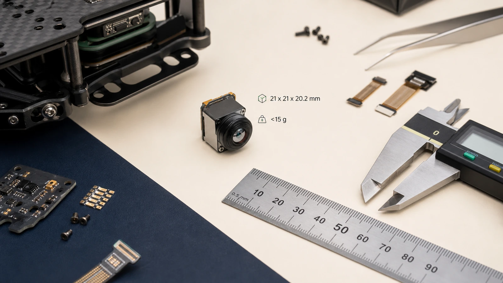
AeroMini’s published 21 x 21 x 28 mm dimensions and <20 g weight exclude the lens and flange. Those references are useful when screening compact UAV payloads, robotics heads, outdoor field devices and OEM products where space is already contested. Freeze the bracket against matched CAD for the selected lens, tailboard and mounting, with the complete assembly mass confirmed separately. The current AeroMini datasheet does not provide a dimensioned assembly drawing; its interface illustrations cannot supply the missing clearances.
The handoff should include lens projection, connector direction, cable bend radius, host PCB location, enclosure window thickness, bracket wall, vibration isolation, and service access. This is especially important when the core moves from a lab bench to a drone payload or outdoor field unit. A 21 mm core can still lose the mechanical argument if the cable exits into a bracket wall.
4. Put procurement documents into the technical review
Europe and North America buyers often need datasheets, matched assembly drawings, electrical interface references, product specifications and compliance-related materials before a sample can become an approved part. If the project requires an NDAA statement, request the applicable materials for the exact configuration, destination market and intended use. Document availability and procurement eligibility need review; a generic module description does not establish either.
Do not treat documentation as a post-sample admin task. Ask during RFQ, and tie the request to the exact model, lens, firmware, interface path, destination market, and intended use. That careful wording prevents a common failure: engineering likes the sample, but purchasing cannot move because the document package was never requested.
Attach the current AeroMini datasheet and the product FAQ’s Linux driver, examples and SDK guidance to the review. The FAQ identifies resources for AeroMini; match them to the actual board, firmware, host, output format and rate before use. Resource availability alone does not prove the software will run on a particular host. On the illustrated connectors, POWER_IN1 on the 16-pin connection and POWER_IN2 on the 26-pin connection are 5 V inputs only; do not apply 12 V to either. Use the matched Type-C board guide for that separate configuration.

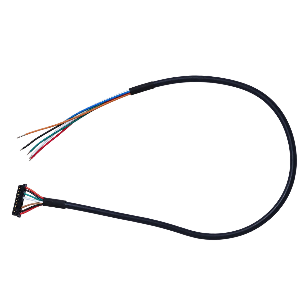
high definition thermal camera core selection chart for compact payloads
| Decision area | What to confirm | Useful RFQ evidence | Risk if skipped |
|---|---|---|---|
| Image requirement | What higher definition must improve | Mission, working distance, target size, scene width | Paying for resolution that does not solve the field problem |
| Output path | Selected AeroMini board, USB/CVBS path, format, rate and recording route | Host board, receiver, recorder, display, latency expectation | Good bench image, failed field handoff |
| Control path | Board-specific serial electrical levels, connector and command workflow | Processor platform, matched board guide, firmware and software resources | No clean way to configure or control the core |
| Mechanical fit | Module, lens, connector, bracket, cable, window | Payload envelope, bracket sketch, cable exit, weight target | A compact core that cannot assemble reliably |
| Procurement | Documents and market requirements | Datasheet, matched assembly CAD, interface reference, configuration-specific compliance/NDAA review request | Sample works but approval stalls |
Featured product facts: AeroMini 640 as the primary high definition thermal camera core path
CAMCUDA AeroMini 640 is the primary comparison for this compact-payload handoff: a 640 x 512 uncooled LWIR core with lens and tailboard choices that need to be specified together. Lower-resolution sensing remains useful when the mission, power budget or cost target does not justify a 640-class image. Start with the field requirement, then compare the complete configurations.
| Product model | CAMCUDA AeroMini 640 |
|---|---|
| Detector type | VOx uncooled infrared detector |
| Resolution | 640 x 512 |
| Pixel pitch | 12 um |
| Spectral range | 8–14 um |
| Non-radiometric frame rate | 60 Hz factory default; 30 Hz factory option. Imaging only, without temperature measurement. |
| Radiometric frame rate | 25 Hz; availability enquiry only. Confirm measurement requirements and the selected configuration. |
| NETD | ≤30 mK at 25 °C, F/1.0 |
| Tailboard choices | USB + CVBS + MIPI, or Type-C + CVBS. Confirm the supplied board and its connection guide. |
| Digital and analog video | Board- and firmware-dependent format/rate; confirm the actual USB, CVBS or MIPI host path. Do not assume simultaneous outputs at the factory camera rate. |
| Control | Board-specific serial interface; the illustrated 16-pin USB/CVBS schematic labels RS232_RX and RS232_TX. |
| Illustrated power inputs | POWER_IN1 on the 16-pin connection and POWER_IN2 on the 26-pin connection: 5 V only. Use a separate matched guide for Type-C. |
| Typical module power | <0.5 W at 25 °C; complete-kit consumption may differ. |
| Dimensions, excluding lens and flange | 21 x 21 x 28 mm; request matched CAD for the complete assembly. |
| Weight, excluding lens and flange | <20 g; confirm the selected assembly mass separately. |
| Operating temperature | −40 °C to +80 °C |
Use the internal paths for the next decision: compare thermal imaging cores, review thermal modules, check uncooled thermal modules, find documents in support downloads, and send final questions through CAMCUDA contact.
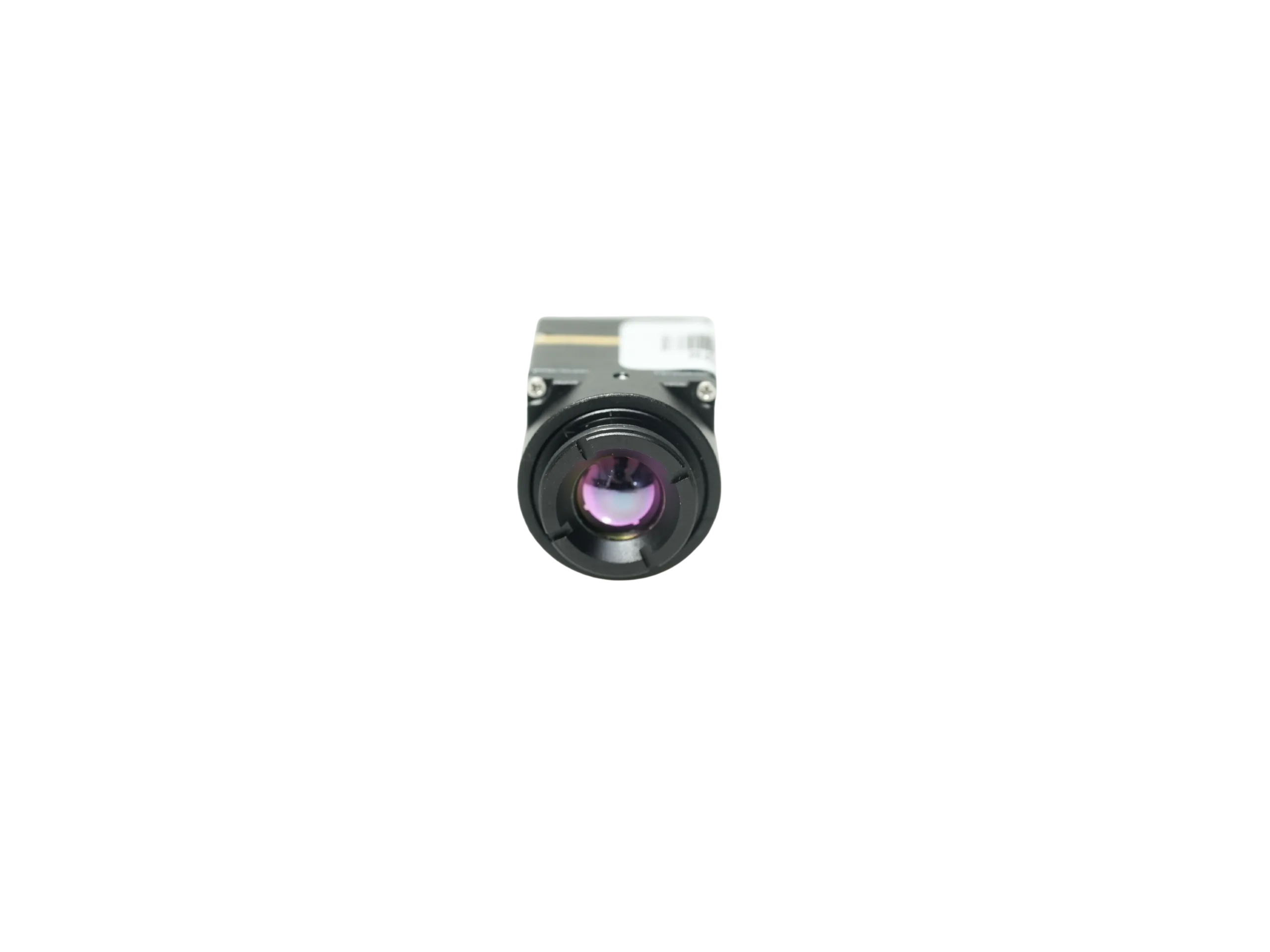
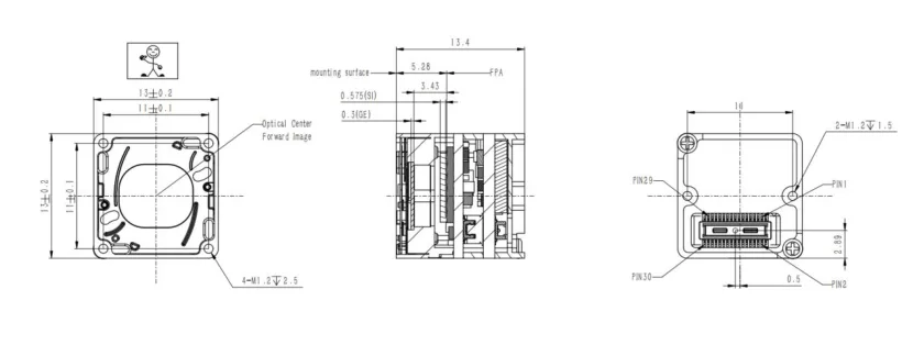
For a separate bare-core comparison, CAMCUDA SuperMini 640 / 640T uses a 640 x 512, 8 um detector with NETD ≤40 mK at 25 °C, F/1.0. SuperMini 640 is 50 Hz imaging-only; 640T is 30 Hz thermographic. Its 13 x 13 x 13.4 mm dimensions and <3.5 g weight exclude optics and boards, and typical core power is ≤0.5 W at 25 °C, excluding the expansion board. The smaller bare-core footprint must be compared with the host electronics, optics and board added.
SuperMini uses its own 30-pin core interface, multiple power rails, 1.8 V UART and an external video-buffer IC for CVBS. Its V1.0.0 product manual defines the connector, power requirements and sequence; AeroMini wiring diagrams and SDK resources do not establish compatibility. The drawing below is only the SuperMini bare-core reference. An AeroMini bracket still needs separate CAD matched to its ordered lens, tailboard and mounting.
Application case: utility payload review before a sample order
A distributor is helping a European integrator source a compact thermal module for a utility inspection payload. The first request is simple: a high definition thermal camera core with good image detail, low weight, and sample availability. The better request is more specific.
The team plans low-altitude inspection around equipment yards and outdoor service sites. The operator needs live viewing during flight, the engineering bench can start with USB video, and the aircraft-side recorder may require an analog path. The bracket has a narrow payload bay, so AeroMini’s 21 x 21 x 28 mm and <20 g references are useful for the first screen, with their lens/flange exclusions kept explicit. The buyer still needs full assembly mass, cable exit and lens clearance confirmed. The sample order records the imaging or radiometric version, factory rate, lens and exact tailboard; the acceptance test includes the aircraft recorder.
The corrected RFQ points the buyer to CAMCUDA’s drone thermal camera application page for UAV payload context and the outdoor field thermal imaging page for a later field-use decision. The outdoor page distinguishes a finished handheld observation device from an OEM module for the buyer’s own enclosure and host. A fixed-site build needs separately specified protective housing, mounting, power and environmental validation. Describe that second deployment early enough that its output and enclosure requirements can be reviewed before choosing the sample.
Common mistakes when evaluating a high definition thermal camera core
- Using resolution as the whole specification. Higher pixel count must connect to working distance, scene width, field report detail, or AI/vision input requirements.
- Choosing the output after the bracket is designed. The selected board’s USB, CVBS, MIPI and serial-control paths should be reviewed before connector and recorder decisions are frozen.
- Treating 21 mm as the total payload size. AeroMini’s 21 x 21 x 28 mm reference excludes lens and flange; lens, cable bend, tailboard, window and bracket details still matter.
- Waiting to ask for documents. Matched assembly CAD, interface references, product specifications and any configuration-specific compliance/NDAA document review should be part of the first serious RFQ.
- Ignoring adjacent deployments. A UAV payload may later become an outdoor field device, vehicle-mounted unit, or monitoring product with different enclosure assumptions.
RFQ checklist for a compact high definition thermal camera core
| RFQ line | What to provide |
|---|---|
| Application | Drone payload, outdoor field monitoring, robotics, industrial inspection, security monitoring, or OEM device |
| Target product | AeroMini 640 with the imaging/radiometric version, factory rate, lens and tailboard; SuperMini 640 / 640T as a separately specified bare-core comparison |
| Image task | Working distance, target size, scene width, lens/FOV preference, reporting requirement |
| Video output | Selected board, video format and rate, USB/CVBS/MIPI needs, display/recorder/downlink details |
| Control and host | Board-specific serial electrical levels, processor, firmware, matched connector guide, software resources and host validation |
| Mechanical | Payload envelope, cable exit, bracket sketch, enclosure window, weight target, vibration context |
| Documents | Datasheet, matched assembly CAD, electrical interface reference, board/firmware/host resources, configuration-specific compliance/NDAA review request |
| Commercial | Sample quantity, expected annual quantity, destination country, schedule, intended use |
Send the handoff notes before the sample leaves the bench
If your team is evaluating a high definition thermal camera core, send CAMCUDA the mission, target distance, video path, control interface, mechanical envelope, document needs, and destination market. Include the imaging or radiometric version, factory rate, lens and tailboard so engineering can review an AeroMini 640 assembly against the system. If the team is considering SuperMini 640 / 640T, include its separate bare-core power, host and mechanical integration plan.
Review AeroMini 640 | Compare SuperMini 640 / 640T | Compare thermal imaging cores | Request an engineering RFQ
FAQ: high definition thermal camera core sourcing
What counts as a high definition thermal camera core for OEM work?
In this sourcing context, buyers are usually looking beyond low-resolution sensing toward a module such as a 640 x 512 uncooled LWIR core. The exact choice should still depend on field distance, lens/FOV, output path, and integration limits.
Is AeroMini 640 a finished camera?
No. AeroMini 640 is a thermal camera core for OEM and payload integration. The lens and tailboard define the supplied assembly. Host electronics, enclosure, power, lens/FOV matching, video path and documents should be reviewed during RFQ.
Why does CVBS matter if the module has USB video?
Some payloads, legacy displays, analog transmitters and field recorders need composite analog video. Confirm the selected AeroMini board’s CVBS output, receiver format and complete recording path during RFQ; a USB bench preview does not validate the field receiver.
Can a 21 mm module still be hard to integrate?
Yes. AeroMini’s 21 x 21 x 28 mm dimensions and <20 g weight exclude lens and flange. Lens projection, cable routing, tailboard and host-board position, bracket clearance and the enclosure window can still create fit issues. Request CAD for the complete ordered assembly before freezing the bracket.
When should an NDAA statement be requested?
Request the applicable documents during RFQ when your procurement process requires them. Identify the exact configuration, destination market and intended use, then have the procurement team review availability and applicability. Do not infer blanket NDAA eligibility from a product family or a sample order.
Should a high definition thermal camera core always be used for drone payloads?
No. Higher definition is useful when the mission needs more detail or later review value. Smaller, lower-resolution modules can be better for simple sensing, low-power devices, or tight cost targets.
What external information helps evaluate the module?
Useful references include field mission requirements, host processor details, receiver or recorder specs, bracket drawings, operating environment, procurement document requirements, and expected sample-to-production quantity.
What is the biggest RFQ mistake?
The biggest mistake is asking only for a high-resolution core. A stronger RFQ describes the image task, output path, control path, mechanical envelope, documents, destination market, and sample quantity.
How many internal CAMCUDA pages should be reviewed?
Start with the AeroMini product page, its datasheet and SDK guidance in the product FAQ, then the thermal imaging cores category, support downloads and contact/RFQ. Review the drone thermal camera or outdoor field thermal imaging page for the mission. If you are comparing SuperMini, use its separate product page and manual; a fixed number of pages matters less than resolving the open handoff decisions.