DJI Thermal Camera vs Custom Drone Payloads: OEM 640 LWIR Integration Guide
DJI Thermal Camera vs Custom Drone Payloads: OEM 640 LWIR Integration Guide
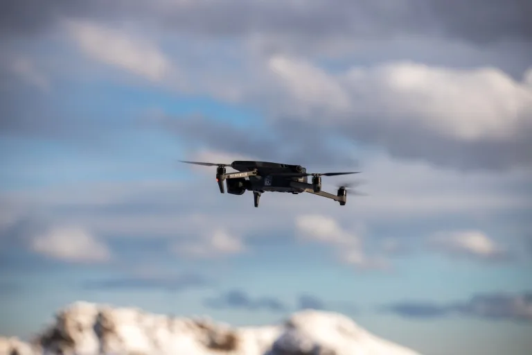
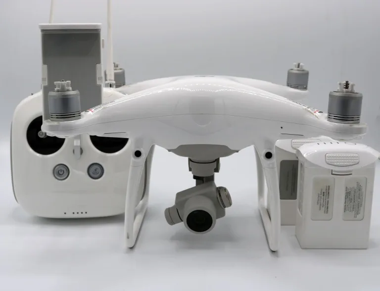
For commercial UAV developers, defense contractors, and robotics integrators, picking the right thermal imaging payload comes down to a hard engineering trade-off. Off-the-shelf turnkey rigs—think the DJI Mavic 3 Enterprise Thermal (M3T), Matrice 30T, or the Zenmuse H20T/H30T series—made aerial infrared accessible by packaging optics, radiometric sensors, and flight hardware into ready-to-fly platforms. But when you are building custom airframes in the shop for proprietary computer vision, edge-AI target tracking, strict low-SWaP (Size, Weight, and Power) envelopes, or projects with procurement restrictions, the documented hardware and software access of each platform matters.
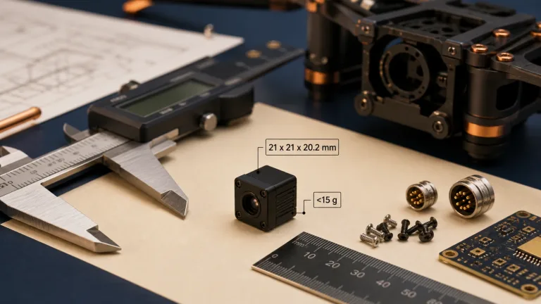
Here’s the deal: building a custom uncooled Long-Wave Infrared (LWIR) payload around OEM micro-cores—like the CAMCUDA SuperMini 640 / 640T (sub-3.5 g bare core excluding optics and expansion boards, 8 µm pixel pitch) or the CAMCUDA AeroMini 640 (also linked as AeroMini 640; 12 µm pitch, 21 × 21 × 28 mm excluding lenses and flanges)—gives you control over payload architecture. Confirm accessible output formats, end-to-end latency and system cost for the selected board; these are not guaranteed by the AeroMini 640 PDF. This guide breaks down the real engineering differences between turnkey DJI thermal gear and custom OEM 640 × 512 LWIR integrations, covering sensor physics, low-noise power routing, digital video pipelines, radiometric extraction, and open-source PX4/MAVLink drone architectures.
Table of Contents
- 👉 1. DJI Thermal Camera Systems vs. Custom Open-Architecture OEM Payloads
- 👉 2. Thermal Sensor Physics: 8 μm vs. 12 μm Pixel Pitch and Optical Selection
- 👉 3. Low-SWaP Mechanical and Electrical Integration (Power, Pinouts, Thermals)
- 👉 4. Video Pipelines & Embedded Telemetry: MIPI CSI-2, BT.656, and USB 2.0
- 👉 5. Radiometric Telemetry vs. Qualitative Thermal Imaging in UAV Missions
- 👉 6. OEM 640 Thermal Core Showcase & Technical Reference
- 👉 7. Technical Specification Matrix: CAMCUDA SuperMini 640 vs. AeroMini 640 vs. COTS Baseline
- 👉 8. Step-by-Step Architecture: Integrating an OEM 640 Core into a PX4/MAVLink Drone
- 👉 9. Deep-Dive Engineering FAQ
1. DJI Thermal Camera Systems vs. Custom Open-Architecture OEM Payloads
Industrial drone deployments cover serious ground—utility line inspection, wildland firefighting, perimeter defense, ISR scouting, and precision mapping. Turnkey commercial platforms get operators in the air quickly, but hardware teams building proprietary systems run into severe roadblocks with closed architectures.
The Closed Ecosystem Dilemma
Turnkey systems package the LWIR sensor, lens assembly, stabilization gimbal, radio link, and ground software into an integrated unit. DJI Mavic 3 Enterprise Thermal and Matrice 30T use model-specific imaging pipelines and transmission systems. The M3T uses DJI O3 Enterprise. These interfaces shape custom development:
- ⚠️ Compressed Video Bottlenecks: A compressed display stream is not equivalent to calibrated temperature data. The M3T records H.264 thermal video and 16-bit R-JPEG thermal stills; check the supported file or SDK data path for temperature analysis rather than assuming a live video feed contains radiometric samples.
- ⚠️ Fixed Optical FOV: The M3T thermal camera has a fixed 61° diagonal field of view and a 40 mm equivalent focal length. Its integrated lens is not an interchangeable OEM lens mount; select an OEM optical assembly when your design needs a different field of view.
- ⚠️ Supply Chain & NDAA Constraints: Procurement requirements can constrain the aircraft, components, suppliers and data handling used in a project. Review the applicable contract and the complete system; choosing an OEM core or avoiding cloud telemetry alone does not establish compliance.
- ⚠️ Costly Depot Repairs: If a drone takes a hit or crashes on a job site, replacing an integrated gimbal payload may require vendor service. Check repair scope, spare availability and turnaround for the selected aircraft before committing to fleet deployment.
The Open OEM Modular Advantage
When you build around an OEM micro-core—like the CAMCUDA SuperMini 640 or CAMCUDA AeroMini 640—you can design the host imaging and computing stack. A companion computer can handle thermal video while PX4 or ArduPilot handles flight control, with MAVLink providing supported telemetry and camera control. The Dronecode Foundation supports the PX4 ecosystem. Hardware interfaces, drivers and analytical data paths still need to be integrated and validated.
- ✅ Direct Edge AI Access: Evaluate the documented MIPI or parallel-video path for the selected core and host, such as a Jetson or Raspberry Pi-based companion computer. Receiver support, drivers, pixel format and measured end-to-end latency depend on the implementation.
- ✅ Interchangeable Optics: Match optical focal lengths to specific mission profiles—from 3.7 mm wide-angle situational lenses up to 11 mm narrow-field inspection optics.
- ✅ Custom Radio Transceivers: Choose a radio and local video/telemetry architecture that meet the project’s link and data-handling requirements. Cloud independence and security depend on the complete implementation.
2. Thermal Sensor Physics: 8 μm vs. 12 μm Pixel Pitch and Optical Selection
Uncooled Long-Wave Infrared (LWIR) detectors operate across the 8–14 μm atmospheric window. They use Vanadium Oxide (VOx) microbolometer focal plane arrays (FPAs) to convert incoming infrared thermal radiation into electrical resistance changes. When designing a custom drone gimbal, physical sensor dimensions influence optical mass, payload balance, and spatial resolution.
Pixel Pitch Dynamics: 8 μm vs. 12 μm
Pixel pitch (p) measures the center-to-center distance between neighboring detector pixels on the FPA. Moving from standard 12 μm detectors to cutting-edge 8 μm microbolometers makes a major difference in low-SWaP airborne gimbal design:
- ⚙️ 8 μm Pixel Architecture (CAMCUDA SuperMini 640): Shrinking the pixel pitch to 8 μm drops the active area of a 640 × 512 array down to roughly 5.12 × 4.10 mm (6.56 mm diagonal). Because the detector is smaller, the focal length required to achieve a target Field of View (FOV) decreases significantly. This can enable smaller optical assemblies; lens material, total payload mass and gimbal torque still depend on the selected assembly.
- ⚙️ 12 μm Pixel Architecture (CAMCUDA AeroMini 640): A 12 μm pitch array yields a 7.68 × 6.14 mm active area (9.83 mm diagonal). For the same field of view it requires a longer nominal focal length. Pixel pitch alone does not determine NETD or performance in difficult atmospheric conditions.
Calculating Spatial Resolution: IFOV and GSD
To estimate near-axis spatial sampling at a target distance, calculate the Instantaneous Field of View (IFOV):
IFOV (mrad) ≈ p (μm) / f (mm)
Here p is detector pixel pitch in micrometers (μm), f is optical focal length in millimeters (mm), and IFOV is in milliradians (mrad). This nominal near-axis estimate does not describe distortion or sampling across a wide-angle image.
For a nadir view of a flat ground plane at height H above ground level, estimate Ground Sample Distance (GSD) near the image center. The table uses the displayed, rounded IFOV values:
GSD (cm/pixel) ≈ H (m) × IFOV (mrad) / 10
Optical Selection Guide: CAMCUDA SuperMini 640 (8 μm Pitch)
| Focal Length (f) | Aperture | Field of View (H × V) | IFOV (Spatial Resolution) | GSD at 50 m AGL | GSD at 100 m AGL |
|---|---|---|---|---|---|
| 3.7 mm | F1.0 | 90.0° × 68.2° | 2.16 mrad | 10.8 cm/pixel | 21.6 cm/pixel |
| 6.1 mm | F1.0 | 46.6° × 37.6° | 1.31 mrad | 6.55 cm/pixel | 13.1 cm/pixel |
| 8.7 mm | F1.0 | 40.0° × 32.2° | 0.92 mrad | 4.60 cm/pixel | 9.20 cm/pixel |
| 11.0 mm | F1.0 | 24.9° × 20.0° | 0.73 mrad | 3.65 cm/pixel | 7.30 cm/pixel |
The EMVA 1288 Standard provides camera-characterization methods; citing it does not certify this module or establish NETD across its operating-temperature range. The published SuperMini specification is NETD ≤40 mK at 25°C, F1.0. For a dual-sensor electro-optical design, include the required thermal/visible fields of view, synchronization and host interfaces in your configuration enquiry.
3. Low-SWaP Mechanical and Electrical Integration (Power, Pinouts, Thermals)
Integrating an OEM thermal module into a compact airborne gimbal requires careful power-supply and interface design, clean power filtering, and proper thermal dissipation to avoid thermal drift or sensor noise injection.
Electrical Pinout & Power Requirements
The CAMCUDA SuperMini 640 series connects through an ultra-compact Hirose DF40C-30DP-0.4V(51) 30-pin board-to-board connector. Provide all rails and follow the manufacturer’s noise limits and power-on sequence; the manual does not identify these external rails as detector analog-bias supplies:
| Power / Signal Path | Published Voltage Requirement | Integration & Noise Tolerance Notes |
|---|---|---|
| MAIN_POWER | 3.8 V to 5.2 V (Typical 5.0 V) | 10 mV p-p maximum peak-to-peak noise. |
| +3.3 V Rail | 3.28 V to 3.32 V | 10 mV p-p maximum noise. |
| +1.8 V Rail | 1.78 V to 1.82 V | 1 mV RMS maximum noise (1 Hz to 50 kHz). Validate the supply design against the manual. |
| Digital Video Output | 8-bit LVCMOS; 2-lane MIPI CSI-2 | 640: BT656; 640T: CDS3 image plus temperature data. BT656 and MIPI cannot operate simultaneously. |
| Serial Command Interface | UART (1.8 V Logic Levels) | TX/RX defined from core perspective. Requires level shifting for 3.3V MCUs. |
| Analog Video / USB | USB 2.0 D+/D-; CVBS Pin | CVBS requires an external video-buffer IC. TMS6102V100F022 is an optional USB board; confirm host format and driver. |
Mechanical Packaging & Thermal Management
The bare CAMCUDA SuperMini 640 core measures just 13 × 13 × 13.4 mm and weighs under 3.5 g, excluding the lens, flange and user expansion board. Validate the complete assembly in flight:
- ⚙️ Conductive Thermal Path: Plan a stable thermal path and keep heat from nearby processors away from the module where practical. Select interface materials and verify temperature drift with the actual enclosure, airflow and operating cycle; a generic thermal-pad rating does not establish measurement performance.
- ⚙️ Vibration Isolation: Measure the airframe’s vibration environment and validate the bracket, cable routing and any damping with the complete optical assembly. The appropriate mount stiffness and damping depend on payload mass and resonance; no single grommet hardness guarantees artifact-free images.
4. Video Pipelines & Embedded Telemetry: MIPI CSI-2, BT.656, and USB 2.0
Getting infrared video off the detector and into your flight computer depends on your downstream processing architecture.
1. 2-Lane MIPI CSI-2 Interface
The SuperMini family provides a 2-lane MIPI interface through the 30-pin connector. A Jetson or Raspberry Pi host needs a compatible receiver, driver and capture-mode configuration before frames can enter a V4L2 pipeline. CAMCUDA SuperMini 640T uses RAW8 CSI-2 packets that must be reconstructed into 16-bit image and temperature words, low byte first. Verify the model-specific format and measure end-to-end latency; CSI-2 alone does not establish plug-and-play support or a latency limit.
2. 8-Bit LVCMOS / ITU-R BT.656 Interface
For custom FPGA, DSP, or avionics boards, the CAMCUDA SuperMini 640 provides an 8-bit Low-Voltage CMOS digital stream adhering to the ITU-R BT.656 standard. The imaging model runs at 50 Hz; implement the receiver against the documented timing and output mode. CAMCUDA SuperMini 640T instead provides CDS3 image plus temperature data at 30 Hz. BT656 and MIPI outputs cannot operate simultaneously.
3. USB 2.0 via Expansion Board (TMS6102V100F022)
For bench testing or a compatible host, the optional TMS6102V100F022 expansion board provides a 4-pin USB 2.0 interface for both SuperMini variants. Confirm the board firmware, exposed USB format, driver and temperature-data access before selecting OpenCV, ROS/ROS 2 or GStreamer. The board name alone does not establish UVC operation or out-of-the-box software compatibility.
For field deployment best practices, review our detailed guide on outdoor thermal imaging field integration.
5. Radiometric Telemetry vs. Qualitative Thermal Imaging in UAV Missions
When selecting a 640 LWIR core, you need to match the core type to your operational objectives: qualitative visual imaging or absolute radiometric measurement.
Qualitative Thermal Imaging (CAMCUDA SuperMini 640)
Qualitative cores prioritize high-contrast imagery for visual monitoring or edge detection algorithms. The CAMCUDA SuperMini 640 supports grayscale stretching, contrast enhancement, noise reduction and detail enhancement. Its 8-bit imaging output shows relative scene contrast rather than calibrated per-pixel temperature; palette support depends on the output path.
- ✅ Fast 50 Hz Frame Rate: Supports responsive imaging; motion blur and total latency still depend on the scene, detector response and full video path.
- ✅ Primary Applications: Search and rescue (SAR), nighttime security, situational awareness, and livestock monitoring where thermal contrast is the primary goal.
Radiometric Thermography (CAMCUDA SuperMini 640T)
The CAMCUDA SuperMini 640T is the thermographic model. CDS3 carries YUV422 image data plus temperature data, while the MIPI path carries image and temperature words. Published measurement accuracy applies under the stated conditions; emissivity, reflected radiation and the environment also affect temperature interpretation.
- ⚙️ 30 Hz Calibrated Stream: The documented thermographic frame rate for the 640T model.
- ⚙️ Dual Calibrated Ranges:
- Low Range: −20°C to +150°C (for applications such as building envelopes, insulation audits, and solar PV cell hotspot localization).
- High Range: +100°C to +650°C (for applications such as power distribution grids, substations, flare stacks, and structural firefighting).
- ⚙️ Pixel-to-Temperature Conversion: Reconstruct the 640T temperature words according to the selected CDS3 or MIPI format, then use the conversion for the actual output mode:
640T TEMP → mode-specific conversion → temperature (°C)
See Appendix 2 of the Product Manual V1.0.0 for the ND and HD formulas. Select the actual output mode, not a mode inferred from the value. These conversions do not apply to imaging-only CAMCUDA SuperMini 640 or AeroMini.
6. OEM 640 Thermal Core Showcase & Technical Reference
Here is the full technical breakdown for CAMCUDA’s uncooled LWIR camera modules built for low-SWaP drone and robotic payloads.
CAMCUDA SuperMini 640 / 640T Ultra-Light LWIR Thermal Camera Module
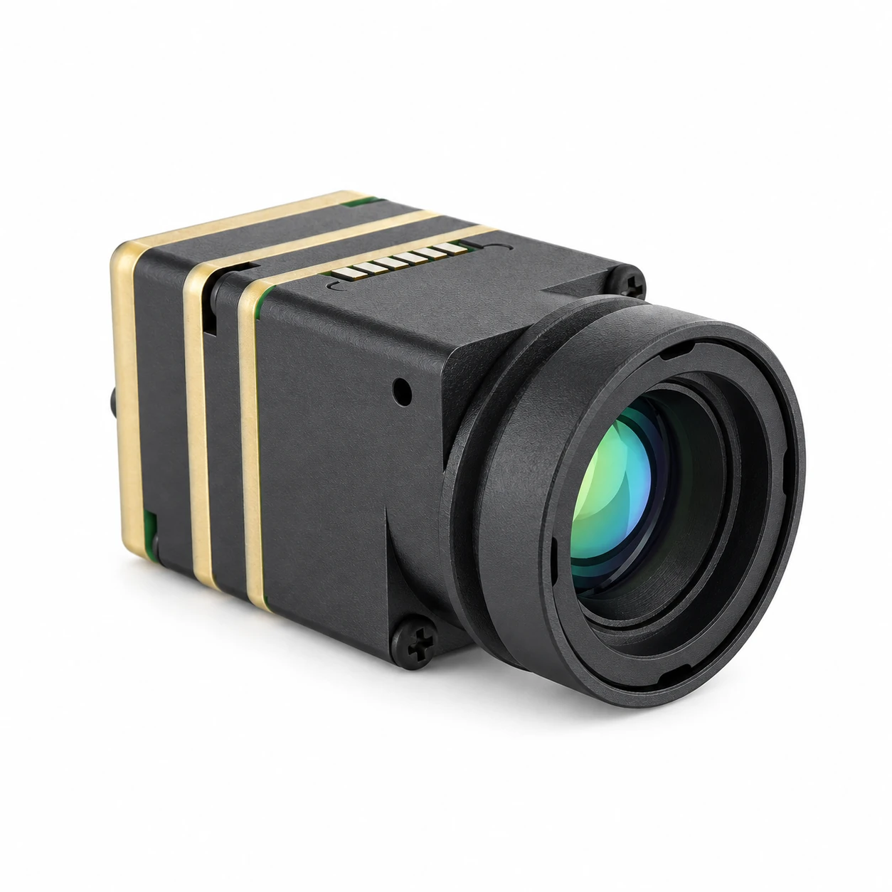
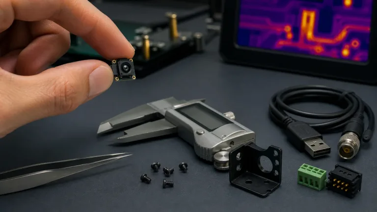
Overview: The CAMCUDA SuperMini 640 / 640T combines a 640 × 512 uncooled VOx detector, an 8 μm pixel pitch, and a 13 × 13 mm footprint in an ultra-light core weighing less than 3.5 g, excluding optics and expansion boards. Built specifically for low-SWaP integration in compact drones, micro-gimbals, FPV platforms, and embedded vision systems, it consumes ≤0.5 W typical core power at 25°C, excluding expansion board. The product photograph shows a lens-equipped assembly, not the bare-core measurement envelope.
Two Factory Models:
- ✅ CAMCUDA SuperMini 640 (Imaging Only): Runs at 50 Hz for imaging without temperature measurement. Features 8-bit LVCMOS / BT656 and 2-lane MIPI interfaces; BT656 and MIPI cannot operate simultaneously.
- ⚙️ CAMCUDA SuperMini 640T (Thermographic): Runs at 30 Hz. Outputs calibrated CDS3 and MIPI temperature streams across dual ranges (−20°C to +150°C and +100°C to +650°C).
Athermal F1.0 Lens Options:
- ⚙️ 3.7 mm (Wide Angle): 90.0° × 68.2° FOV, F1.0, 2.16 mrad IFOV
- ⚙️ 6.1 mm (Wide Field): 46.6° × 37.6° FOV, F1.0, 1.31 mrad IFOV
- ⚙️ 8.7 mm (Balanced Field): 40.0° × 32.2° FOV, F1.0, 0.92 mrad IFOV
- ⚙️ 11.0 mm (Narrow Field): 24.9° × 20.0° FOV, F1.0, 0.73 mrad IFOV
Technical Specifications:
- ⚙️ Detector: VOx uncooled infrared focal-plane array (8–14 μm LWIR)
- ⚙️ Resolution & Pitch: 640 × 512 pixels, 8 μm pixel pitch
- ⚙️ NETD Sensitivity: ≤40 mK @ 25°C, F1.0
- ⚙️ Core Dimensions & Mass: 13 × 13 × 13.4 mm, <3.5 g (bare core, excluding optics and expansion boards)
- ⚙️ Electrical Interface: Hirose DF40C-30DP-0.4V(51) 30-pin connector
- ⚙️ Power Requirements: MAIN_POWER 3.8–5.2 V (typ 5 V), +3.3 V (3.28–3.32 V), +1.8 V (1.78–1.82 V); maximum noise: 10 mV p-p, 10 mV p-p and 1 mV RMS (1 Hz–50 kHz), respectively
- ⚙️ Video & Control: 640: 8-bit LVCMOS/BT656; 640T: CDS3; 2-lane MIPI as documented for the selected model. BT656 and MIPI are not simultaneous. UART uses 1.8 V logic; TMS6102V100F022 is an optional USB expansion board
CAMCUDA AeroMini 640 · 640 × 512 / 12 μm thermal module
CAMCUDA AeroMini 640 combines a 640 × 512 VOx detector, 12 μm pixels and an 8–14 μm LWIR response. Dimensions are 21 × 21 × 28 mm and weight is under 20 g, both excluding lenses and flanges. Typical module power is below 0.5 W at 25 °C; complete-kit consumption may differ. Non-radiometric imaging ships at 60 Hz by default with a 30 Hz factory option. The 25 Hz radiometric version is currently out of stock and enquiry only, with 9, 13 or 18 mm lenses and interface to be confirmed; no online purchase or pre-order is available. Its published −20 to +550 °C range applies only to the radiometric version; accuracy and RAW data format require confirmation.
AeroMini 640 specification source: AeroMini 640 datasheet (MINI640 Integrated EN PDF). The 9 mm lens is specified at 48.7° × 38.6° H × V, F/1.0. Non-radiometric online lens options are 4, 7, 9, 13, 18, 25, 35 and 50 mm. The 7 mm FOV is 64° × 52°; the 18 mm FOV is 24.2° × 19.5°. The PDF also lists 15, 60 and 75 mm reference entries. Non-radiometric units ship at 60 Hz by default, with a 30 Hz factory option at the same price. The current product page specifies NETD ≤30 mK at 25 °C, F/1.0. Illustrated POWER_IN1/POWER_IN2 pins on the 16-pin/26-pin USB/CVBS/MIPI connections are 5 V only; do not apply 12 V to them. The separate Type-C board needs its matched guide. Confirm the selected board, firmware and host using the model-specific SDK FAQ and AeroMini technical documentation folder; these imaging-board resources do not confirm a radiometric interface.
| Detector | Uncooled VOx |
|---|---|
| Resolution | 640 × 512 pixels |
| Pixel pitch | 12 μm |
| Spectral response | 8–14 μm |
| Frame rate | Non-radiometric: 60 Hz default; 30 Hz factory option. Radiometric: 25 Hz, currently out of stock and enquiry only; no online purchase or pre-order. |
| NETD | ≤30 mK at 25 °C, F/1.0 |
| F-number | F/1.0 |
| Polarity | White hot / Black hot |
| Supply voltage | Family table: 5 V or 12 V, board-dependent. Illustrated POWER_IN1/POWER_IN2 pins: 5 V only; do not connect to 12 V. |
| Typical power at 25 °C | <0.5 W typical module power; complete-kit consumption may differ |
| Digital video | YUV, USB, BT.656; board/firmware dependent. Confirm enabled format and host compatibility. |
| Analog video | CVBS, PAL, NTSC; availability depends on the selected board |
| Serial communication | UART, RS232, RS422; availability depends on the selected interface board |
| Dimensions | 21 × 21 × 28 mm, without lenses and flanges |
| Weight | <20 g, without lenses and flanges |
| Measurement range | Published −20 °C to +550 °C, radiometric version only; accuracy and RAW data format require confirmation |
| Radiometric lens options | 9 / 13 / 18 mm only; availability enquiry, interface to be confirmed |
| Operating temperature | −40 °C to +80 °C |
| Storage temperature | −50 °C to +85 °C |
| Humidity | 5–95%, non-condensing |
Compare AeroMini 640 lenses and request a configuration quote →
7. Technical Specification Matrix: CAMCUDA SuperMini 640 vs. AeroMini 640 vs. COTS Baseline
Here is a direct side-by-side comparison between CAMCUDA’s OEM thermal cores and an off-the-shelf COTS benchmark payload (DJI Mavic 3 Enterprise Thermal specifications). AeroMini 640 below refers to the current AeroMini 640 product; core-only and integrated-aircraft figures are not interchangeable:
| Specification Attribute | CAMCUDA SuperMini 640 / 640T | CAMCUDA AeroMini 640 | COTS Commercial Baseline (e.g., DJI M3T) |
|---|---|---|---|
| Detector Architecture | Uncooled VOx Microbolometer | Uncooled VOx | Uncooled VOx Microbolometer |
| Array Resolution | 640 × 512 pixels | 640 × 512 | 640 × 512 pixels |
| Pixel Pitch | 8 μm | 12 μm | 12 μm |
| Spectral Band | 8 to 14 μm (LWIR) | 8–14 μm | 8 to 14 μm (LWIR) |
| Thermal Sensitivity (NETD) | ≤40 mK @ 25°C, F1.0 | ≤30 mK at 25 °C, F/1.0 | ≤50 mK @ F1.0 |
| Native Frame Rate | 50 Hz (640) / 30 Hz (640T) | Non-radiometric: 60 Hz default; 30 Hz factory option. Radiometric: 25 Hz, currently out of stock and enquiry only. | 30 Hz |
| Core Dimensions (W × H × D) | 13 × 13 × 13.4 mm, excluding optics and expansion boards | 21 × 21 × 28 mm, excluding lenses and flanges | Permanently integrated payload |
| Bare Core Weight | < 3.5 g, excluding optics and expansion boards | <20 g, excluding lenses and flanges | Not specified as a comparable bare-core mass; integrated aircraft camera |
| Optical Selection | 3.7 mm, 6.1 mm, 8.7 mm, 11 mm | Online non-radiometric: 4 / 7 / 9 / 13 / 18 / 25 / 35 / 50 mm. 15 / 60 / 75 mm: enquiry. 9 mm: 48.7° × 38.6° H × V. | Fixed 61° DFOV; 40 mm equivalent focal length |
| Power Consumption | ≤0.5 W typical at 25°C, excluding expansion board | <0.5 W typical module power at 25 °C; complete kit may differ | Integrated airframe bus draw |
| Video Output Interfaces | 640: LVCMOS/BT656; 640T: CDS3 image plus temperature; 2-lane MIPI per model. BT656/MIPI not simultaneous. USB via optional board. | Board/firmware dependent: YUV, USB, BT.656; CVBS/PAL/NTSC. Match 16-pin/26-pin documentation or the separate Type-C guide. | DJI O3 Enterprise; H.264 thermal video |
| Radiometric Capability | 640T only: −20°C to +150°C and +100°C to +650°C | 25 Hz; 9 / 13 / 18 mm enquiry only. Published −20 to +550 °C; accuracy, RAW format and interface require confirmation. | High gain: −20°C to +150°C; low gain: 0°C to +500°C |
| Hardware-Level Access | Documented video/control protocols; matched receiver, parsing and host driver required | Confirm enabled output protocol and host driver for the selected board | Model/firmware-specific SDK and file access; not a generic OEM camera interface |
8. Step-by-Step Architecture: Integrating an OEM 640 Core into a PX4/MAVLink Drone
Wiring up an OEM 640 LWIR payload on an open-source flight stack—such as a Holybro Pixhawk 6X running PX4 Autopilot—involves four core engineering stages. The outline below is an integration plan, not a validated CAMCUDA/PX4 software package:
Stage 1: Mechanical Gimbal Balancing and Cable Routing
The CAMCUDA SuperMini 640 bare core weighs less than 3.5 g, excluding optics and expansion boards. Weigh the selected lens, boards, cabling and complete assembly before choosing a 2-axis or 3-axis gimbal; bare-core mass does not establish assembled payload mass or compatibility with a particular gimbal controller:
- ⚙️ Center the thermal module right on the gimbal pitch/roll axis intersection to minimize motor holding torque.
- ⚙️ Use the matched 30-pin board-to-board connector and a validated cable or adapter. Route the harness with suitable bend radius and strain relief, then check its effect on gimbal motion.
Stage 2: Power Conditioning and Grounding
To reduce supply-related image artifacts when the airframe’s motors and Electronic Speed Controllers (ESCs) are operating:
- ⚙️ Size the input power stage for the aircraft battery’s full operating range, transient load and module startup requirements; verify the selected interface board’s approved input.
- ⚙️ For the bare SuperMini core, provide MAIN_POWER at 3.8–5.2 V plus the specified +3.3 V and +1.8 V rails. Meet the manual’s noise limits and power-on timing with a validated regulator/filter design; a single 5 V feed is not the complete bare-core supply specification.
- ⚙️ Plan return-current paths, grounding and shielding for the selected high-speed video interface, then test supply ripple and image stability with the motors running.
Stage 3: Embedded Linux V4L2 Video Ingestion Pipeline
For a Jetson-based host, first implement and validate the receiver, sensor driver and device-tree configuration for the chosen model and output mode. The GStreamer command below is an illustrative host-side streaming example only: it requires a Jetson with a hardware H.265 encoder, matching JetPack/plugins and an already working /dev/video0 that exposes 640 × 512 GRAY8 at 50 fps. Orin Nano has no NVENC hardware encoder, so the nvv4l2h265enc example does not apply to Orin Nano. The module connector or datasheet does not establish these host prerequisites:
gst-launch-1.0 v4l2src device=/dev/video0 ! \
  'video/x-raw, width=640, height=512, format=GRAY8, framerate=50/1' ! \
  videoconvert ! \
  nvvidconv ! \
  'video/x-raw(memory:NVMM), format=NV12' ! \
  nvv4l2h265enc bitrate=4000000 ! \
  rtph265pay config-interval=1 pt=96 ! \
  udpsink host=192.168.1.100 port=5600
If those host prerequisites are met, this example requests 50 fps GRAY8 input, converts it to NV12, encodes H.265 at 4 Mbps and sends RTP/UDP. It does not capture or preserve calibrated 640T temperature words, and it is not a direct RAW8/16-bit thermographic decoder. Measure actual latency and validate the pipeline on the selected host and firmware.
Stage 4: MAVLink Camera Protocol Telemetry Binding
To expose supported camera functions to a ground station such as QGroundControl or Mission Planner, evaluate a MAVLink camera service on the companion computer. The service and each module-specific control mapping require implementation and testing:
- ⚙️ MAVLink Camera Protocol: Use
CAMERA_INFORMATIONandVIDEO_STREAM_INFORMATIONmessages to describe the camera and its supported stream to the GCS; the actual video travels over its configured transport. Match the advertised URI and protocol to the implementation, including the RTP/UDP example above. - ⚙️ UART Serial Control: Map only supported ground-station commands to documented module commands and validate acknowledgements and state changes. The SuperMini core UART uses 1.8 V logic; this does not establish AeroMini electrical compatibility. NUC/FFC, palette and zoom controls depend on model, interface and firmware, and are not automatically implemented by MAVLink.
9. Deep-Dive Engineering FAQ
Can you replace the stock visible camera on consumer DJI drones with an OEM thermal camera?
How does an OEM 640 LWIR core compare to turnkey payloads like the DJI Mavic 3 Thermal?
Do I need a standard thermal imaging core or a radiometric version for drone payload integration?
Standard Imaging Cores (e.g., CAMCUDA SuperMini 640 at 50 Hz): These modules provide relative scene contrast for search and rescue, nighttime observation and other imaging tasks. Image processing and palette support depend on the selected output path; image levels are not calibrated temperatures.
Radiometric Cores (e.g., CAMCUDA SuperMini 640T at 30 Hz): These provide calibrated temperature data within the documented −20°C to +150°C and +100°C to +650°C bands. Select the correct output mode, conversion and measurement conditions before logging temperatures for solar-panel or utility inspections. AeroMini’s separate 25 Hz radiometric version is currently out of stock and enquiry only, with 9/13/18 mm lenses and interface to be confirmed.
To confirm configuration, availability, sample lead time and delivery destination, use the SuperMini product/RFQ page or the AeroMini configuration enquiry.
📚 References & Further Reading
- Industry Standard: EMVA 1288 Standard for Optical Characterization
- Industry Standard: Dronecode Foundation Open-Source UAV Ecosystem
- Product Reference: CAMCUDA SuperMini 640 / 640T Product Manual V1.0.0
- Related Guide: CAMCUDA Outdoor Field Thermal Imaging Applications
- AeroMini resources: AeroMini datasheet, model-specific SDK FAQ and technical documentation folder. Match the selected board, firmware and host; radiometric interface availability requires separate confirmation.
Technical author: Daniel · Hardware Support
Sales contributors: Vivian, Lena and Sophie