DJI Drone with Thermal Camera vs Custom OEM Payloads: B2B Integration Guide
DJI Drone with Thermal Camera vs Custom OEM Payloads: B2B Integration Guide
Aerial infrared inspection supports critical infrastructure monitoring, search and rescue (SAR), precision agriculture, and industrial non-destructive testing (NDT). For robotics engineering leads, drone system architects, and procurement managers, an off-the-shelf DJI drone with thermal camera—such as the Mavic 3 Thermal (M3T) or Matrice 350 RTK with a compatible Zenmuse H20T or H30T gimbal—is a useful starting point. These turnkey systems combine flight management, visible and thermal imaging, stabilization and model-specific temperature-measurement workflows. Compare the exact aircraft, camera and software configuration with the inspection requirement before choosing between a packaged system and an OEM payload.
As commercial drone operations scale and requirements become specialized, fixed optics, supported API access, payload limits, wireless video formats and replacement costs become practical design constraints. Review those constraints on the actual platform rather than assuming every commercial system has the same restrictions. For a growing fleet or specialized field robot, a custom OEM long-wave infrared (LWIR) core is another architecture to evaluate.
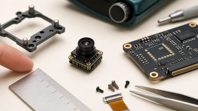
Integrating custom OEM thermal cores into purpose-built airframes or custom secondary payload brackets lets engineering teams dial in their Size, Weight, Power, and Cost (SWaP-C). You can select application-matched optics and documented video interfaces, then build the host processing pipeline around them. That flexibility comes with responsibility for drivers, receiver compatibility, calibration, licensing, system qualification and lifecycle support; it does not establish unrestricted firmware or intellectual property rights.
Table of Contents
- 👉 1. DJI Drone with Thermal Camera: Turnkey Capabilities and Integration Limits
- 👉 2. Turnkey Enterprise Systems vs Custom OEM Thermal Payloads: Architectural Breakdown
- 👉 3. SWaP-C Engineering for Airborne LWIR Payloads
- 👉 4. Optical Engineering: Focal Length, IFOV, and Johnson’s DRI Criteria
- 👉 5. Video Pipeline, Protocols, and Edge AI Integration
- 👉 6. Core Technical Specifications: CAMCUDA OEM Thermal Modules
- 👉 7. Step-by-Step OEM Payload Integration Guide for Custom Airframes
- 👉 8. Frequently Asked Questions (FAQ)
1. DJI Drone with Thermal Camera: Turnkey Capabilities and Integration Limits
Turnkey enterprise drones streamline aerial thermography for field crews. M3T combines thermal, wide-angle and telephoto cameras; H20T and H30T payloads also include a laser rangefinder. Available sensors and inspection functions depend on the package. For roof surveys, utility inspections or solar-array checks, a supported aircraft-and-camera combination can reduce hardware integration work, while flight preparation, training and local operating requirements still apply.
Advantages of Turnkey Commercial Solutions
- ✅ Factory-Integrated Deployment: Turnkey packages combine supported aircraft, camera, gimbal and pilot software. This reduces custom wiring and driver work, but crews still need model-specific setup, firmware checks, calibration checks, training and an approved operating plan before flight.
- ✅ Pre-Integrated Software Suites: Supported pilot software can provide spot meters, area high/low temperature bounding boxes, dynamic isotherms, and simultaneous split-screen side-by-side RGB/thermal streaming within the documented aircraft, camera and software configuration.
- ✅ Factory-Tuned Gimbal Dynamics: Integrated stabilization is designed around the supplied camera assembly. A custom payload requires separate mass, center-of-gravity, inertia and vibration checks; factory tuning does not eliminate all angular jitter under every flight condition.
Critical Engineering Bottlenecks in Scaled B2B Deployments
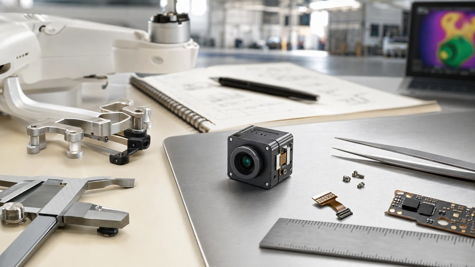
For specialized industrial inspection or autonomous field robotics, evaluate where the documented commercial platform fits and where a separate OEM payload requires additional engineering:
- ⚠️ Optical Configuration: Thermal fields of view differ: M3T specifies 61° diagonal, H20T 40.6° diagonal, and H30T 45.2° diagonal. These are not a universal wide-angle range. At a required inspection standoff, calculate the target pixels for the actual lens and detector. A different lens or payload needs manufacturer-supported integration and calibration; do not assume a field lens swap is available.
- ⚠️ Video Pipelines and SDK Scope: Live video, saved radiometric files and direct sensor-bus access are different interfaces. M3T specifies H.264 video, 16-bit R-JPEG thermal stills and O3 Enterprise transmission; supported DJI SDK paths depend on the aircraft and firmware. Define the required pixel format and measured end-to-end latency, then verify the documented interface rather than assuming raw live video is either universally available or universally blocked.
- ⚠️ Fleet Maintenance & Replacement Costs: Confined-space inspections and frequently operated docking systems require a lifecycle cost model. A modular airframe with an uncooled thermal module can make some components separately serviceable, but compare actual parts, labor, qualification, spares, downtime and warranty costs. An OEM architecture does not guarantee a lower total cost.
- ⚠️ Procurement and Compliance Requirements: Check the buyer, funding source, jurisdiction and current contract requirements against the exact aircraft, component origins, software and data handling. Blue UAS is a specific program; NDAA-related restrictions are not a universal ban on all foreign-made equipment. Neither an open-source flight stack nor a custom airframe with an OEM thermal core establishes eligibility, cybersecurity approval or European regulatory conformity. Obtain the required configuration-specific documentation and review.
2. Turnkey Enterprise Systems vs Custom OEM Thermal Payloads: Architectural Breakdown
Choosing between deploying standard enterprise thermal drones and engineering a dedicated payload setup comes down to hardware flexibility, pipeline control, and lifecycle costs. Let’s break down how these two engineering philosophies compare head-to-head.
| Architectural Dimension | Turnkey Commercial Drone (e.g., DJI Enterprise) | Custom OEM LWIR Payload Architecture |
|---|---|---|
| Thermal Core Flexibility | Optics and payload interfaces depend on the exact aircraft and camera; M3T uses a fixed thermal lens. | Selected CAMCUDA AeroMini 640: non-radiometric 9 mm F1.0, USB + CVBS + MIPI. Review other lens assemblies separately. |
| Video Signal Output | M3T: O3 Enterprise transmission and H.264 video; supported file and SDK access are separate paths. | AeroMini USB + CVBS + MIPI package; verify board, firmware, formats and enabled output combination. Measure full-path latency. |
| Edge Computing & AI Integration | Development access depends on aircraft, payload, SDK and firmware support; review the documented combination. | Jetson, Raspberry Pi or another host needs a compatible receiver, driver and measured processing budget; PyTorch support is a host integration task. |
| Airframe Compatibility | Supported payloads and batteries are aircraft-specific; enterprise platforms differ in expansion options. | Custom UAV or UGV mounting requires qualification of mass, balance, vibration, power and environmental protection. |
| Power Bus Architecture | Use the selected aircraft’s documented battery and payload-power interfaces. | AeroMini illustrated POWER_IN1/POWER_IN2: 5 V only, never 12 V. SuperMini requires three separate core rails. |
| Bill of Materials (BOM) Economics | Compare actual aircraft, payload, spares, software, service and downtime costs. | Include optics, carrier, host, enclosure, integration, testing and production support; savings depend on the complete design. |
3. SWaP-C Engineering for Airborne LWIR Payloads
In aerial robotics, payload mass, power draw, center of gravity and inertia all enter the aircraft design budget. Their effect on flight endurance and control behavior depends on the complete airframe and operating profile. Optimize Size, Weight, Power, and Cost (SWaP-C) together, and verify the assembled payload rather than extrapolating flight performance from a bare-core figure.
1. Payload Mass and Gimbal Inertia
Complete multi-sensor gimbals and bare cores represent different integration levels. For example, DJI specifies 920 ±5 g for the complete H30T gimbal, including several sensors and stabilization hardware. Its mounting and inertia requirements cannot be compared directly with an OEM core alone. Include the chosen lens, carrier, cables, enclosure and stabilization system before estimating gimbal loads and aircraft endurance.
The CAMCUDA AeroMini 640 reference is <20 g and 21 × 21 × 28 mm, excluding the lens and flange. The SuperMini 640 reference is <3.5 g and 13 × 13 × 13.4 mm, excluding the lens, flange and user expansion board. A custom mount can use these as starting values, but the final assembly needs its own measured mass and envelope:
- ⚙️ Budget the complete payload: Compare assembled mass and measured energy use on the actual airframe. No fixed percentage weight reduction or extra flight time follows from the core specifications alone.
- ⚙️ Check small-aircraft operating requirements: Payload mass counts toward the aircraft total. The FAA requires registration for all Part 107 drones, including those below 250 g. Under EASA open-category rules, a C0 class-marked product and a privately built aircraft below 250 g are distinct cases; low mass alone does not remove applicable operating restrictions.
- ⚙️ Simplifies multi-sensor setups: Evaluate a thermal core alongside LiDAR, multispectral or RGB cameras within the measured mass, power, center-of-gravity and maximum takeoff weight (MTOW) budgets.
2. Electrical Power Budgeting
Power must be compared at the same integration level. The complete DJI H30T gimbal is specified at 28 W, while AeroMini lists <0.5 W typical module consumption at 25°C; complete-kit consumption may differ. SuperMini lists ≤0.5 W typical core power at 25°C, excluding the expansion board. Add host processing, converters, interfaces, gimbal drive and startup demand before calculating the aircraft power budget.
The illustrated AeroMini POWER_IN1 / POWER_IN2 pins are 5 V only, never 12 V. Its family table mentions board-dependent supplies, which must not be transferred to those pins. Use the supplied board definition and qualified regulation from the aircraft bus. SuperMini is a separate design requiring MAIN_POWER, +3.3 V and +1.8 V rails; neither core should be wired directly to an unregulated flight battery from a generic voltage claim.
4. Optical Engineering: Focal Length, IFOV, and Johnson’s DRI Criteria
Optical selection starts with the inspection distance, target size and detail needed for the task. A packaged thermal camera has a documented optical configuration; an OEM design allows selection from the chosen family’s supported optics. Pixel geometry is useful for planning, but Johnson-style criteria and similar pixel thresholds do not guarantee field detection, recognition, identification or temperature accuracy.
Understanding IFOV and Spatial Resolution
The Instantaneous Field of View (IFOV) estimates the angular width of one detector pixel near the optical axis. For small angles, pixel pitch divided by focal length gives a nominal IFOV; image detail also depends on focus, lens performance, contrast and processing. A near-axis target-plane pixel footprint is approximately range × IFOV in radians:
IFOV (mrad) ≈ Pixel Pitch (µm) / Focal Length (mm); footprint (m) ≈ range (m) × IFOV (mrad) / 1000
The selected AeroMini configuration uses a 12 μm, 640 × 512 detector and 9 mm F1.0 lens, with a published 48.7° × 38.6° horizontal × vertical FOV. SuperMini uses an 8 μm detector and a different optical family. Keep published model-specific FOV separate from idealized pitch/focal-length calculations, particularly for wide-angle optics:
- ⚙️ Wide Fields for Coverage: A wider field covers more area at a given distance but leaves fewer pixels across a fixed-size target. Verify edge performance, distortion and the target footprint for close-range facade surveys, canopy inspection or indoor mapping. Optical coverage alone does not establish obstacle-avoidance capability.
- ⚙️ Balanced Fields for Inspection: The selected 9 mm AeroMini lens is one concrete imaging configuration. Compare its documented FOV with the required survey swath and target detail. Choose distance, orientation and overlap for the task; a nominal pixel calculation is not a human-detection range specification.
- ⚙️ Narrower Fields for Standoff Detail: A narrower field can place more pixels across a target, with less scene coverage. For utility or wildfire inspection, confirm the chosen family’s lens availability, complete assembly and required operating distance before procurement. Do not infer safe separation or guaranteed target recognition from focal length alone.
Johnson’s Criteria and a Geometric Range Reference
The table is a hypothetical 640 × 512, 12 μm rectilinear sensor model, not AeroMini or SuperMini lens specifications. For a 1.8 m × 0.5 m human-sized target, it explicitly uses the 0.5 m width across the image and chosen thresholds of 1.5, 6 and 12 pixels. Range R = 0.5 × f / (N × 0.012), with R in metres and f in millimetres. Ideal FOV = 2 atan(sensor extent / 2f). These geometric thresholds are not validated detection, recognition or identification criteria; atmosphere, contrast, orientation, motion, optics and processing remain unmodelled.
| Hypothetical Focal Length | Ideal Rectilinear FOV (H × V) | Nominal IFOV | Range: 1.5 Pixels Across Width | Range: 6 Pixels Across Width | Range: 12 Pixels Across Width |
|---|---|---|---|---|---|
| 4.9 mm | 76.2° × 64.2° | 2.45 mrad | 136.1 m | 34.0 m | 17.0 m |
| 9.1 mm | 45.8° × 37.3° | 1.32 mrad | 252.8 m | 63.2 m | 31.6 m |
| 13.0 mm | 32.9° × 26.6° | 0.92 mrad | 361.1 m | 90.3 m | 45.1 m |
| 19.0 mm | 22.9° × 18.4° | 0.63 mrad | 527.8 m | 131.9 m | 66.0 m |
| 35.0 mm | 12.5° × 10.0° | 0.34 mrad | 972.2 m | 243.1 m | 121.5 m |
5. Video Pipeline, Protocols, and Edge AI Integration
Video delivery and radiometric export are separate design choices. M3T specifies H.264 video and 16-bit R-JPEG thermal stills; the file depth does not establish a raw live sensor interface. Review documented SDK access for the exact platform. For OEM integration, specify whether the host needs display imagery, minimally processed pixels or calibrated temperature data, then validate capture, buffering, timestamps and end-to-end latency.
1. Low-Latency Analog CVBS for Real-Time Piloting
For inspection piloting and operator feedback, measure the full camera-to-display delay under representative conditions. CVBS can avoid a digital encoding stage, but sensor integration, image processing, transmission and display still add latency. Neither a universal <20 ms end-to-end figure nor a lag-free feed is established for the configurations here.
The selected AeroMini package includes a CVBS path; confirm PAL/NTSC mode, signal levels, termination and board pinout before connecting a receiver. SuperMini’s CVBS pin requires an external video-buffer IC, so it is not the same wiring contract. Validate image interruptions and the documented NUC workflow, and retain other situational-awareness measures. The CVBS thermal camera module analog video integration guide is background; the supplied board documentation controls the wiring.
2. Digital USB UVC and MIPI-CSI for Onboard Edge AI Inference
For anomaly detection, thermal mapping or hot-spot review on a companion computer, choose the output format that the application actually requires. A Jetson, Raspberry Pi or other processor needs a compatible receiver, driver and validated processing pipeline; a physical USB or MIPI connector does not establish that the host can capture or infer at the sensor frame rate:
- ⚙️ USB Video Class (UVC): Confirm the selected USB board, firmware, enumeration, pixel format and host driver before integrating V4L2, OpenCV, ROS2 or GStreamer. A USB connection is not itself proof of UVC compatibility. The A3 vision standards overview is general background, not certification of either camera. Request AeroMini’s board-matched software through its SDK documentation entry point.
- ⚙️ MIPI-CSI Interface: Verify lane configuration, electrical levels, timing, receiver format and driver support before connecting to the host. SuperMini specifies a 2-lane MIPI path; MIPI and BT.656 cannot operate simultaneously. Models trained in PyTorch still need a measured capture-to-inference budget. SuperMini 640 imaging runs at 50 Hz; AeroMini imaging uses 60 Hz default or a 30 Hz factory option, without guaranteeing host inference at those rates.
6. Core Technical Specifications: CAMCUDA OEM Thermal Modules
The current comparison below uses the AeroMini non-radiometric 9 mm USB + CVBS + MIPI configuration as the main OEM imaging option, with SuperMini 640 imaging as a compact bare-core alternative. Neither is a 160-class, microcontroller SPI or very-low-power replacement. Temperature measurement requires a separately verified thermographic model and data path.
CAMCUDA AeroMini 640 Non-Radiometric 9 mm OEM Configuration
The CAMCUDA AeroMini 640 configuration here pairs a 640 × 512, 12 μm VOx detector with a 9 mm F1.0 lens and USB + CVBS + MIPI interface package. It is non-radiometric: 60 Hz factory default or 30 Hz factory option, without temperature measurement. The package includes a USB cable requiring customer soldering. The standard configuration does not provide RAW or minimally processed output; that requirement needs a separate customization assessment. Confirm board, firmware, format and host compatibility before purchase.
The separate 25 Hz AeroMini radiometric version is currently out of stock and enquiry only, with no online purchase or pre-order. Documented lens options are 9/13/18 mm; its interface and measurement details require confirmation. Do not transfer those thermographic capabilities to the imaging configuration shown here.
| Resolution & Detector | 640 × 512 uncooled VOx; non-radiometric imaging |
|---|---|
| Pixel Pitch & Spectral Band | 12 μm | 8–14 μm LWIR |
| Thermal Sensitivity (NETD) | ≤30 mK at 25°C, F1.0 |
| Output Frame Rate | 60 Hz factory default / 30 Hz factory option |
| Module Weight & Envelope | <20 g; 21 × 21 × 28 mm, excluding lens and flange |
| Operating Power & Voltage | <0.5 W typical module power at 25°C; kit may differ. Illustrated POWER_IN1/POWER_IN2: 5 V only, never 12 V. |
| Output Video Interfaces | Selected USB + CVBS + MIPI package; confirm board, firmware and host format |
| Selected Lens / FOV (H × V) | 9 mm F1.0; 48.7° × 38.6°. Other assemblies need separate review. |
| Operating Temperature | −40°C to +80°C operating; not a temperature-measurement range |
CAMCUDA SuperMini 640 Imaging Core Comparison
The CAMCUDA SuperMini 640 is a 640 × 512, 8 μm VOx imaging core at 50 Hz, with NETD ≤40 mK at 25°C, F1.0. Its 13 × 13 × 13.4 mm and <3.5 g references exclude the lens, flange and user expansion board. Typical core power is ≤0.5 W at 25°C, excluding the expansion board. Final optics, interface, supplied items and host integration need configuration review.
Keep low-resolution sensing separate: 160-class resolution, a microcontroller SPI video link or substantially lower power remains an independent procurement requirement. Neither AeroMini nor SuperMini 640 is an equivalent substitute for that combination. A UART control interface does not establish that a microcontroller can receive the video stream.
SuperMini 640T is the separate 30 Hz thermographic model. Its CDS3 path carries image and temperature data; MIPI RAW8 transport is reassembled into 16-bit image and temperature values, low byte first. Use the selected model’s manual and firmware format. These temperature-data functions do not apply to imaging-only SuperMini 640 or AeroMini imaging.
| Resolution & Total Pixels | 640 × 512 uncooled VOx; imaging-only SuperMini 640 |
|---|---|
| Detector Pitch & Spectral Band | 8 μm | 8–14 μm LWIR; NETD ≤40 mK at 25°C, F1.0 |
| Factory Model / Frame Rate | 640 imaging: 50 Hz. Separate 640T thermography: 30 Hz. |
| Core Envelope / Weight | 13 × 13 × 13.4 mm; <3.5 g; excludes lens, flange and user expansion board |
| Operating Power & Supply | ≤0.5 W typical core power at 25°C, excluding expansion board; MAIN_POWER 3.8–5.2 V plus +3.3 V and +1.8 V rails |
| Host Interface & Connector | 30-pin connector; 8-bit LVCMOS / BT656 or 2-lane MIPI, not simultaneous BT656 + MIPI; 1.8 V UART; external CVBS buffer required |
| Imaging / Thermography Boundary | 640 has no temperature measurement. 640T only: CDS3 image + temperature and MIPI RAW8 transport reassembled into 16-bit values, low byte first. |
7. Step-by-Step OEM Payload Integration Guide for Custom Airframes
Integrating a bare OEM microbolometer module into a custom drone platform (like an ArduPilot/PX4-powered quadcopter or VTOL) requires solid mechanical, electrical, and thermal fundamentals. Follow this bench checklist to get clean, reliable performance in the air:
Step 1: Optical Selection and Mission Sizing
⚙️ Define inspection distance, target dimensions, detail and temperature-data requirements before CAD. Start with the selected AeroMini 9 mm imaging configuration or a separately reviewed SuperMini optical assembly. Use documented FOV and a nominal pixel model for planning, then validate the actual target. Confirm factory lens alignment, calibration and handling requirements; do not assume lenses are field-swappable or that imaging-only hardware supplies radiometric data.
Step 2: Mechanical Housing and Gimbal Axis Balancing
⚙️ Design the bracket from the selected assembly drawing, allowing lens, flange, board, connector and cable clearance. Support the intended mounting surfaces without loading the optical elements. Measure the complete module, mount and cable mass and balance it about the gimbal axes. Bench-test vibration, control-loop behavior and motor temperature; a bare-core weight or static balance check alone does not establish stable flight.
Step 3: Power Distribution and Ground Isolation
⚙️ Measure camera supply quality with the aircraft electronics and motors operating. AeroMini’s illustrated POWER_IN1/POWER_IN2 inputs need regulated 5 V. SuperMini requires MAIN_POWER 3.8–5.2 V, +3.3 V at 3.28–3.32 V, and +1.8 V at 1.78–1.82 V. Its first two rails specify 10 mV p-p maximum noise; the 1.8 V rail specifies 1 mV RMS over 1 Hz–50 kHz. Follow the model’s startup sequence, grounding and signal-return requirements rather than applying one generic wiring recipe.
Step 4: Electrical Interface Wiring
⚙️ Wire from the model-matched documentation. AeroMini’s 16-pin USB/CVBS and 26-pin MIPI/DVP references do not describe its separate Type-C board. SuperMini uses a different 30-pin connector and Product Manual V1.0.0. Do not reuse AeroMini pin maps or SDK instructions for SuperMini. Check mating orientation, voltage levels, enabled outputs and the exact supplied cable before power-on:
- ⚙️ Analog CVBS Pipeline: Verify the selected board’s supply, grounds, video levels and receiver termination. AeroMini’s illustrated power inputs remain 5 V only; SuperMini needs its specified rails and an external CVBS video-buffer IC. For serial controls, use the family-specific command documentation. SuperMini UART is 1.8 V logic, with TX/RX defined from the core; MAVLink control requires an implemented and tested host bridge.
- ⚙️ Digital USB Pipeline: AeroMini’s selected package includes a USB cable requiring customer soldering. Match its board pinout and host software, then test capture, power and controls with the actual cable. SuperMini’s optional TMS6102V100F022 expansion board provides a 4-pin USB connection for either factory model; confirm supplied items and software separately. Route and restrain cables so they do not load the connector or obstruct gimbal motion.
Step 5: Thermal Dissipation and Aerodynamic Considerations
⚙️ Plan and measure the heat path through the complete payload, including the host processor and expansion boards. Validate warm-up, ambient changes and prop wash against the model’s operating limits and documented NUC workflow. Do not infer an internal thermistor layout, fixed shutter cadence or inevitable calibration cycles from general microbolometer behavior. Keep optical surfaces clean, avoid concentrated radiation sources and follow handling guidance; enclosure airflow and thermal isolation need system testing.
8. Frequently Asked Questions (FAQ)
Can I replace the stock camera on a consumer DJI drone with a thermal camera module?
How does building an OEM thermal payload compare to buying an off-the-shelf DJI Mavic 3 Thermal?
What are the key SWaP and electrical requirements for drone thermal camera integration?
📚 References & Further Reading
- General Standards Background: A3 Vision Standards
- AI Framework: PyTorch
- Related Guide: CVBS Thermal Camera Module Analog Video Integration
- Product Catalog: CAMCUDA Uncooled Thermal Modules
- Company Policies: Privacy Policy
- DJI primary references: Mavic 3 Enterprise Series specifications, H20 Series specifications and H30 Series specifications; use the documented model and supported SDK combination.
- Optical planning background: FLIR guidance on resolution and range modelling and Edmund Optics imaging geometry. The table above is an ideal rectilinear, near-axis pixel-width model, particularly approximate for wide-angle optics, not a quoted manufacturer range claim.
- AeroMini resources: AeroMini datasheet, model-specific SDK FAQ and AeroMini technical documentation folder. Match the board, firmware and host; these are not SuperMini resources.
- SuperMini resources: 640 / 640T product reference and Product Manual V1.0.0. Confirm factory model, complete connector definition and output mode before integration.
Technical author: Daniel · Hardware Support
Sales contributors: Vivian, Lena and Sophie