Drones with Night Vision: Engineering Guide to Thermal Payloads & Low-Light Integration
Drones with Night Vision: Engineering Guide to Thermal Payloads & Low-Light Integration
Drones with night vision support infrastructure inspection, environmental surveys, and search-and-rescue (SAR) work after dark. Digital low-light cameras use available visible or near-infrared light; thermal cameras provide a complementary view of surface radiation. A dual-spectrum payload can help an operator compare the scene across both channels, but the appropriate configuration depends on illumination, weather, subject contrast, and the task. Neither channel guarantees usable imagery in heavy fog or when the subject is hidden behind an opaque obstruction.
Combining a low-light electro-optical (EO) camera with an uncooled long-wave infrared (LWIR) camera can support day/night observation. Onboard processing may provide display composition or supported image-analysis functions, but camera alignment, synchronization, processing time, and the operator display must be evaluated together. A processor's TOPS rating alone does not establish a working frame rate, a tracking capability, or a universal latency limit.
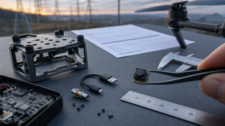
A practical design starts with optical contrast, atmospheric transmission, and Size, Weight, Power, and Cost (SWaP-C) constraints. Power integrity, heat dissipation, and electromagnetic compatibility also need to be checked on the intended installation. This guide compares visible/NIR and LWIR imaging, explains how to assess onboard processing, and outlines the mechanical, electrical, and software evidence needed before selecting an OEM night-vision payload.
Table of Contents
- 👉 1. Optical Physics: Digital Low-Light (EO) vs. Thermal LWIR Payloads
- 👉 2. Embedded Edge AI Architecture: Compute and Latency Requirements
- 👉 3. Flight Avionics, Power Regulation & Telemetry Protocol Integration
- 👉 4. Module comparison for drones with night vision: VisionCube ST Pro vs. DT Pro
- 👉 5. Step-by-Step OEM Integration & Flight Validation Checklist
- 👉 6. Frequently Asked Questions (FAQ)
1. Optical Physics: Digital Low-Light (EO) vs. Thermal LWIR Payloads
For a night inspection or SAR observation task, match the scene information you need to the camera's documented spectral response. Low-light EO and thermal imaging observe different parts of the spectrum and usually rely on different sources of scene contrast:
- ⚙️ Visible Light Spectrum (approximately 0.38–0.75 µm): Ordinary scene detail is primarily formed from reflected daylight or artificial illumination, while lamps and other luminous objects emit their own visible light. Image quality depends on the photons reaching the sensor and its noise characteristics.
- ⚙️ Near-Infrared / Short-Wave Infrared (NIR/SWIR): These are separate bands beyond visible red, with boundaries that vary by convention and camera design. Ambient-temperature night imaging in these bands generally needs reflected ambient or active illumination. Check the actual detector response and atmospheric conditions; SWIR sensitivity should not be inferred from a low-light CMOS specification.
- ⚙️ Long-Wave Infrared (LWIR, commonly around 8–14 µm): Thermal imagers can form images without visible illumination by sensing infrared radiation from the scene. Surface emission, reflected thermal radiation, the atmosphere, and the camera optics all affect the result. Darkness alone does not prevent imaging, but adequate subject-to-background contrast and an unobstructed view remain necessary.
| Operational Parameter | Starlight / Low-Light EO Sensor | Uncooled LWIR Thermal Sensor |
|---|---|---|
| Operational Spectrum | Visible and, where specified, NIR; check sensor, filters, and lens response | Commonly around 8–14 µm; check the module specification |
| Illumination Dependence | Requires adequate ambient or active illumination; usable threshold depends on test conditions | No visible illumination required; contrast and atmospheric transmission still limit performance |
| Obscurants and Occlusion | Fog, smoke, and dust can reduce contrast; opaque objects block the view | May retain useful contrast in some smoke or light fog; dense fog and opaque foliage can block the view |
| Contrast Mechanism | Scene illumination, reflectance, optics, and sensor response | Surface emission and reflected infrared radiation, modified by the atmosphere and optics |
| Illumination Hardware | Optional NIR illumination adds power and range constraints | Passive thermal imaging does not require an illuminator |
| Scene Detail | Color and surface markings may be useful with adequate light, sampling, and contrast | Surface-radiance patterns and outlines; no direct view through an opaque engine enclosure |
Digital Low-Light Sensors (Electro-Optical / Visible)
Back-illuminated CMOS technology and a light-efficient lens can improve low-light imaging, but sensor format and aperture alone do not establish a minimum usable illumination. Compare supplier lux figures only with their stated exposure time, gain, lens, and image-quality conditions. For the intended inspection scene, check whether fine details remain useful at the required output rate; do not assume that a quoted low-light threshold also applies to moving subjects.
In very dark scenes, the useful EO signal may be limited by the available light and sensor noise. Increasing gain amplifies signal and noise, while longer exposure can increase motion blur and reduce the usable frame rate. Active NIR illumination may help within its designed range, but its power demand, beam coverage, and backscatter in fog or dust need evaluation. Test these trade-offs in representative conditions rather than treating any one setting as a cure for darkness.
Uncooled LWIR Thermal Microbolometers
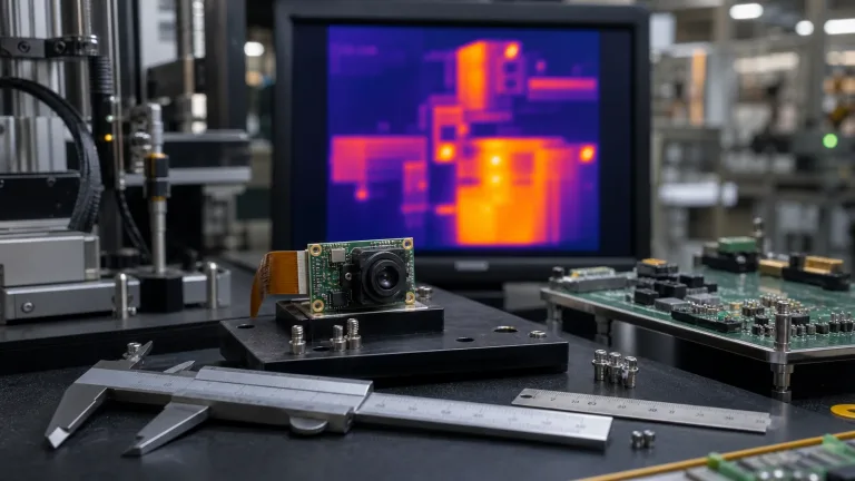
Uncooled LWIR microbolometers are a common way to add thermal imaging to a night-vision payload. Absorbed infrared radiation changes the detector elements' temperature, which the readout electronics convert into an image signal. The documented spectral band, detector material, pixel pitch, and lens combination should be checked for the exact module; they are not established by the label 'thermal camera' alone.
The Stefan–Boltzmann relation, j* = εσT⁴ for a graybody, describes total emitted power per unit area integrated over all wavelengths; an LWIR camera responds only within its spectral band. Wien's wavelength law gives an illustrative blackbody peak near 9.34 µm at 37°C and 7.98 µm at 90°C, so the latter is just below an 8–14 µm band, although it still emits radiation within that band. These examples are not assumptions about a person's skin or an engine's surface temperature. NETD describes thermal sensitivity under specified test conditions; it is neither temperature-measurement accuracy nor a guarantee that a similarly small subject-to-background difference will be resolved in the field.
Dual-Light Fusion and Picture-in-Picture (PIP) Topologies
Thermal imagery can reveal surface-radiance differences in darkness, while a visible image can add color and familiar structural detail when illumination permits. Both depend on the optics, sampling, contrast, and scene. Viewing them together can help an inspector or SAR operator interpret an observation, but combining the channels cannot recover details hidden from both cameras:
- ✅ Spatial Image Fusion: Some systems combine features from the visible and thermal channels after registration. The available method, synchronization, and alignment accuracy are implementation-specific; confirm the supplier's supported modes and inspect the result at representative working distances.
- ✅ Picture-in-Picture (PIP): Where supported, an inset view can help an operator consult both channels. Confirm which stream appears in each view, the output format, switching behavior, and timing. PIP by itself does not establish pixel-level fusion or automatic cross-spectrum identification.
2. Embedded Edge AI Architecture: Compute and Latency Requirements
Sending video to a ground computer adds a communication path and may introduce encoding, buffering, transport, and decoding delays. Onboard processing can reduce dependence on that path for supported local image functions, while ground processing may offer other resources. Compare the complete architectures using measured delay, image quality, power, and loss-of-link behavior for the intended configuration.
Edge Inference Pipelines and Latency Budgets
An EO/LWIR processing pipeline must handle the actual sensor formats, frame timing, input interfaces, and supported processing functions. Request an interface diagram and a list of simultaneously available streams, then check resizing, synchronization, buffering, and output behavior. Model type, arithmetic precision, camera-bus support, and frame rate should come from the selected hardware and software documentation rather than being inferred from its NPU rating.
Define the latency measurement endpoints before comparing figures: sensor exposure to displayed image, or sensor exposure to a documented metadata output, are different tests. Record delay variation and dropped frames as well as typical delay under the intended workload. Frame rate is not exposure time, and neither a processor rating nor an isolated processing-time figure establishes motion sharpness or stability of an integrated control system.
Image-Analysis Functions to Verify
If image-analysis functions are part of the requirement, request their documented behavior and evaluate them on representative inspection or SAR recordings:
- ⚙️ Operator Selection: Check whether a supported interface lets the operator select a subject and how its location and status are displayed. Specify the output format and update behavior required by the observation workflow.
- ⚙️ Detection and Confirmation: If automatic detection is supplied, establish supported object classes, false-alarm behavior, and how an operator confirms a result. Detection is not evidence of autonomous aircraft navigation.
- ⚙️ Temporary Occlusion: Evaluate what the software reports when the selected subject is hidden. Any estimated position should be distinguished from a fresh observation; do not infer a particular prediction algorithm from a feature label.
- ⚙️ Loss and Re-selection: Check how stale or lost observations are indicated and how the operator can confirm or re-select a subject after it returns to view. Recovery time and identity continuity need test evidence.
- ⚙️ Workload Limits: If multiple objects are displayed, measure the useful output rate, identity errors, and processor load on the intended recordings. TOPS alone does not establish a supported number of detections or maintained tracks.
The EMVA GenICam standard defines generic camera interfaces, feature naming, and related software modules. It is a useful reference when a supplier explicitly documents an implementation. A reference to GenICam does not demonstrate that a particular EO/LWIR payload, video output, or SDK is compliant; obtain the relevant interface documentation and test the intended host connection.
3. Flight Avionics, Power Regulation & Telemetry Protocol Integration
Integrating dual-spectrum thermal payloads into UAV platforms requires managing mechanical vibration, thermal dissipation, electrical noise, and any required host communication.
Serial Interfaces and Documented Control Functions
Keep the video path, payload command interface, and aircraft flight-control interface distinct. Before connecting an OEM module to other avionics, obtain the connector pinout, electrical signaling requirements, protocol description, and supported firmware or host software:
- ⚙️ Protocol Compatibility: A physical serial port alone does not establish CRSF, MAVLink, or flight-controller compatibility. Verify the protocol version, message definitions, data direction, and supported functions for both ends of the connection; use only a supplier-documented configuration.
- ⚙️ Payload and Aircraft Responsibilities: Image display or object metadata is not an aircraft command. Document the operator controls and any separate, verified gimbal interface, and confirm the system's behavior when imagery or communication is lost. Flight behavior remains subject to the aircraft's own validated controls and failsafes.
Electrical Power Design & SWaP-C Constraints
Airborne dual-spectrum tracking hardware must operate within strict Size, Weight, Power, and Cost (SWaP-C) boundaries:
- ⚙️ Voltage Input Requirements: Use the exact module's specified input range and connector polarity. Check the installed supply's current capacity, startup behavior, transients, and protection against the manufacturer's limits; a nominal aircraft battery voltage is not enough to establish compatibility.
- ⚙️ Thermal Dissipation: Assess the complete payload's power dissipation and specified operating temperatures in its intended enclosure. Confirm any required heat path with the supplier and verify temperature and processing behavior during sustained operation; available airflow can vary between installations.
- ⚙️ Mechanical Mounting: Check the current mechanical drawing for hole positions, fasteners, clearances, mass, and center of gravity. Validate the mount for the intended vibration environment; a board's external dimensions do not establish compatibility with a standard aircraft stack.
For operators comparing form factors and fixed vs. portable thermal systems, reviewing the handheld thermal imaging camera field buying guide provides useful perspective on detector resolution and sensitivity.
4. Module comparison for drones with night vision: VisionCube ST Pro vs. DT Pro
For UAV engineers, drone manufacturers, and industrial robotic integrators developing day/night platforms, selecting a dual-spectrum payload starts with the visible and thermal fields of view, complete installed mass, power budget, and verified software functions for the intended civilian inspection or observation task. Use the CAMCUDA Thermal Imaging Calculator to estimate field of view and scene coverage from the imaging geometry; these planning estimates do not establish detection or identification performance.
The following comparison uses the current CAMCUDA AI VisionCube specifications: ST Pro combines one visible camera with one thermal camera and 1 TOPS processing; DT Pro combines wide-angle and telephoto visible cameras with one thermal camera and 6 TOPS processing. These are published component references, not measured flight-performance benchmarks.
| Specification Parameter | AI VisionCube ST Pro (1 TOPS) | AI VisionCube DT Pro (6 TOPS) |
|---|---|---|
| Edge AI Compute Core | 1 TOPS; single visible camera plus thermal | 6 TOPS; wide-angle and telephoto visible cameras plus thermal |
| Visible (EO) Video Reference | 1920 × 1080 at 30 Hz | 1920 × 1080 at 30 Hz |
| EO Sensor & Optics | 4 mm; 69° H × 42° V; confirm final sensor BOM | 3.9 mm wide-angle: 72° H × 45° V; 12 mm telephoto: 26° H × 15° V; confirm final sensor BOM |
| EO Min Illumination | No minimum-illumination lux rating verified; confirm exposure, gain and test conditions | No minimum-illumination lux rating verified; confirm exposure, gain and test conditions |
| Thermal Detector Class | LWIR thermal camera; detector material not specified in the current source | LWIR thermal camera; detector material not specified in the current source |
| Thermal Spectral Band & Pitch | 8–14 μm LWIR; 12 μm pixel pitch | 8–14 μm LWIR; 12 μm pixel pitch |
| Thermal Resolution & Rate | 640 × 512 at 50 Hz | 640 × 512 at 50 Hz |
| Thermal Optics & FOV | 9.1 mm; 45.9° H × 36.9° V | 9.1 mm; 45.9° H × 36.9° V |
| Tracking Range Reference | No verified tracking range; validate the selected configuration and scene | No verified tracking range; validate the selected configuration and scene |
| Processing Latency | No verified end-to-end latency; measure the selected pipeline | No verified end-to-end latency; measure the selected pipeline |
| Dynamic Speed Reference | No verified tracking-speed rating; establish a controlled test envelope | No verified tracking-speed rating; establish a controlled test envelope |
| Target Tracking Capacity | No verified concurrent-track count; confirm software and firmware | No verified concurrent-track count; confirm software and firmware |
| Tracking Features / Modes | Picture-in-picture listed; confirm other modes for the selected firmware | Picture-in-picture listed; confirm other modes for the selected firmware |
| Control Protocols & Autopilots | Thermal camera: USB; confirm control protocol and autopilot compatibility | Thermal camera: USB; confirm control protocol and autopilot compatibility |
| Input Voltage Range | 9–16 V processing-board input; confirm supply design | 9–16 V processing-board input; confirm supply design |
| Processing Board Dimensions | 38 × 38 × 29 mm; mounting: 25.5 × 25.5 mm | 38 × 38 × 29 mm; mounting: 25.5 × 25.5 mm |
| Sensor Head Physical Dimensions | Visible: 19 × 19 × 30 mm; thermal: 26 × 26 × 21.1 mm, excluding lens and connectors | Dual-visible assembly: 40.8 × 25 × 26 mm; thermal: 26 × 26 × 21.1 mm, excluding lens and connectors |
Deep Product Showcase: AI VisionCube ST Pro (Single Visible + Thermal)
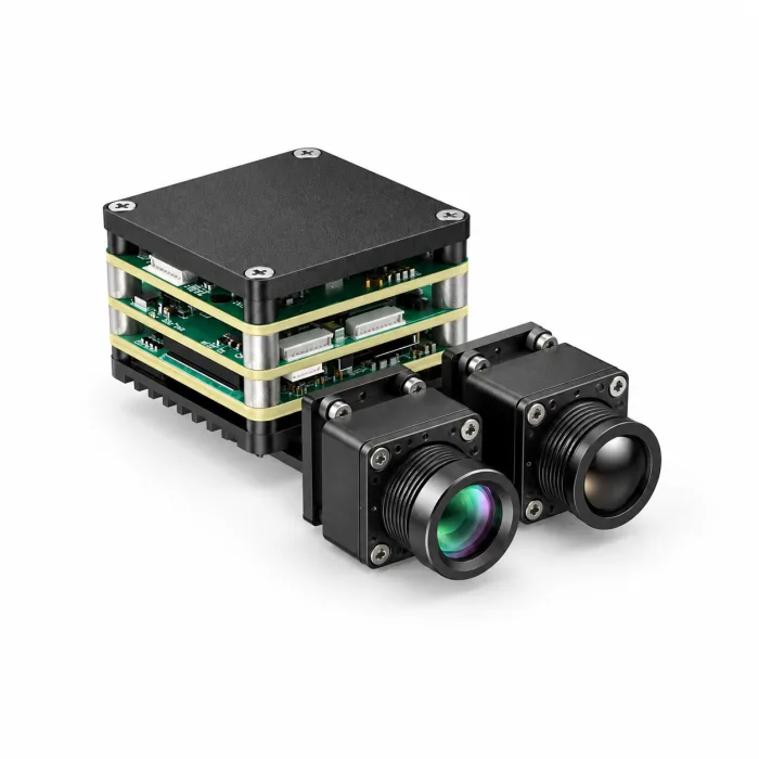
VisionCube ST Pro: 1080p Visible + 640 LWIR Thermal, 1 TOPS
The AI VisionCube ST Pro (CC-VC-STPRO) combines a single visible camera with 1 TOPS processing and a 640 × 512 thermal camera at 50 Hz. Its visible output is 1920 × 1080 at 30 Hz, with a 4 mm lens and a published 69° H × 42° V field of view. The thermal channel uses 12 µm pixels, 9.1 mm optics and a USB interface; its published field of view is 45.9° H × 36.9° V.
For civilian infrastructure inspection, observation or SAR evaluation, ST Pro provides a single visible view alongside thermal imagery and brochure-listed picture-in-picture (PIP). Its processing board is 38 × 38 × 29 mm with a 25.5 × 25.5 mm mounting pattern; the listed 43.8 g is board weight only. Request configuration-specific integration documents to confirm complete kit mass, power consumption, software and environmental limits. Published specifications do not establish tracking range, latency, autopilot compatibility or calibrated temperature-measurement accuracy.
Deep Product Showcase: AI VisionCube DT Pro (Dual Visible + Thermal)
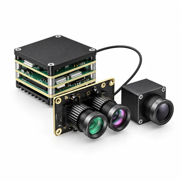
VisionCube DT Pro: Wide-Angle + Telephoto Visible, 640 Thermal, 6 TOPS
The AI VisionCube DT Pro (CC-VC-DTPRO) combines wide-angle and telephoto visible cameras with 6 TOPS processing and a 640 × 512 thermal camera at 50 Hz. Its listed visible output is 1920 × 1080 at 30 Hz. The 3.9 mm wide-angle lens covers 72° H × 45° V; the 12 mm telephoto lens covers 26° H × 15° V. The thermal channel uses the same 12 µm pitch, 9.1 mm optics and USB interface listed for ST Pro.
DT Pro is a candidate when an inspection or observation project needs both wide-angle context and a narrower visible view. Its visible camera assembly measures 40.8 × 25 × 26 mm, while ST Pro’s single visible head measures 19 × 19 × 30 mm. Both use the published 9–16 V board input and 38 × 38 × 29 mm processing-board reference. The Pro thermal head is 26 × 26 × 21.1 mm excluding lens and connectors. Confirm delivered hardware and software before integration; the 6 TOPS label alone does not specify tracking count, latency or control behavior.
5. Step-by-Step OEM Integration & Flight Validation Checklist
Integrating an EO/LWIR payload calls for a documented validation plan covering power, thermal behavior, mechanical installation, image quality, and the intended host interfaces. The following phases are acceptance checks to adapt to the selected module and aircraft; they do not replace the supplier's installation instructions or establish flight readiness by themselves.
Phase 1: Power Integrity and Thermal Management
- ⚙️ 1. Supply Compatibility: Confirm input voltage limits, current demand, connector polarity, and required protection against the module documentation. Choose the supply architecture from those requirements and the measured aircraft power environment.
- ⚙️ 2. Ripple and Transient Validation: Record supply behavior at the payload connector during representative startup and load changes using an appropriate measurement method. Compare the result with the supplier's stated limits and retain the test conditions.
- ⚙️ 3. Thermal Validation: Verify the approved mounting and heat-transfer arrangement during sustained operation at the intended ambient conditions. Select interface materials from the required thermal resistance and mechanical constraints rather than a generic conductivity value.
Phase 2: Host Interface and Software Validation
- ⚙️ 1. Connector and Signal Review: Match the module and host pinouts, signal levels, cable requirements, and grounding or isolation instructions before making a connection. A matching connector or UART label does not establish electrical compatibility.
- ⚙️ 2. Host Configuration: Use the supplier's documented interface, supported software, and configuration procedure. Verify that expected images, status, and commands behave correctly on the chosen host; do not assume a flight-controller firmware supports the payload.
- ⚙️ 3. Operator Controls: Verify only the display and payload controls documented for the module. Record their behavior during startup, disconnection, and recovery, including how the operator recognizes an unavailable function.
Phase 3: Optical Alignment & Co-Boresighting
- ⚙️ 1. Mount and Alignment: Follow the approved mechanical drawing and mounting instructions. Evaluate EO/IR alignment across the intended working-distance range and image field; a single nominal convergence distance is not a universal solution to parallax.
- ⚙️ 2. Focus Verification: Check focus with the installed lens at representative observation distances. Adjust or secure the lens only if the supplier permits it and specifies the procedure and materials.
- ⚙️ 3. Display Alignment: For supported PIP or fusion modes, inspect placement, scale, and synchronization at representative distances. Record residual mismatch and any available settings; do not assume PIP is pixel-aligned fusion or that an alignment tool is supplied.
Phase 4: Bench and Electromagnetic Compatibility Checks
- ⚙️ 1. System Interaction: Use the aircraft manufacturer's approved ground-test procedure to check for image artifacts, frame loss, resets, and interference with other electronics under representative operating loads. Record the configuration and observed limits.
- ⚙️ 2. Latency Verification: Measure the chosen end-to-end path with clearly defined start and finish events. Record typical delay, variation, and frame loss under the intended workload, and compare them with the application requirement rather than reusing another module's processing-time claim.
Phase 5: Application Trials and Acceptance
- ⚙️ 1. Representative Observation: Begin with controlled recordings and stationary inspection subjects, then use the approved aircraft test plan for any field evaluation. Check image usefulness, operator display behavior, and data recording for the intended civilian task.
- ⚙️ 2. Loss of Visibility: On test recordings, check how the system indicates an obscured subject, missing frames, or a lost connection. Verify that the operator can distinguish a current observation from stale data and that any recovery is confirmed correctly.
- ⚙️ 3. Acceptance Record: Document the tested lighting, weather, observation distances, mounting, software versions, temperatures, and power demand. Approve the payload only for the demonstrated application conditions, with unresolved limitations recorded.
For related selection articles, consult the CAMCUDA Engineering Blog. Use the current product documentation and applicable terms of service when reviewing an OEM order.
6. Frequently Asked Questions (FAQ)
Why do consumer low-light night vision drones fail in zero-lux environments compared to uncooled LWIR thermal payloads?
A low-light EO camera needs enough ambient or active illumination in its supported band; its performance cannot be inferred from the zero-lux label alone. Gain cannot create missing light, and longer exposure may increase blur or reduce the output rate. Active NIR illumination can help within its tested conditions.
An LWIR camera needs no visible light, but a useful image still depends on surface-radiance contrast, optics, noise, and the atmosphere. Some smoke or light fog may be less obstructive in thermal imagery, while dense fog and opaque obstructions can prevent a useful view.
What are the engineering advantages of onboard processing versus ground-station video processing?
Onboard processing can support documented image functions without sending every frame to a ground computer for analysis. Ground processing adds a communication path, but actual delay depends on the complete configuration.
Compare measured exposure-to-output timing, delay variation, image quality, power, and behavior during connection loss. TOPS is not an end-to-end latency or tracking-performance specification, and onboard image processing alone does not establish autonomous aircraft operation.
How do OEM dual-spectrum modules interface with open-source flight controllers like BetaFlight and ArduPilot?
Obtain the exact module's pinout, electrical limits, supported video outputs, command protocol, and software documentation. Verify the selected host and firmware against those documents and test the intended functions.
USB, UART, CRSF, MAVLink, and GenICam describe different interfaces or standards; a connector or general standards reference does not establish product compatibility. A displayed object location is also not automatically a flight-control command, so any aircraft or gimbal integration requires its own documented validation.
When should an engineer select AI VisionCube ST Pro versus AI VisionCube DT Pro?
Choose between these configurations by the visible views your inspection, observation or search-and-rescue evaluation needs, along with the installed payload budget and verified integration requirements.
AI VisionCube ST Pro provides one visible camera, 1 TOPS processing and 640 × 512 thermal imaging at 50 Hz. Its 4 mm visible lens is listed at 69° horizontal × 42° vertical field of view. AI VisionCube DT Pro provides wide-angle and telephoto visible cameras, 6 TOPS processing and the same listed thermal resolution and frame rate. Its visible fields of view are 72° horizontal × 45° vertical and 26° horizontal × 15° vertical respectively; both configurations list 1080p visible output at 30 Hz.
Use ST Pro when one visible view meets the evaluation requirements; assess DT Pro when separate wide-angle and telephoto views would help. Neither TOPS rating proves low-light sensitivity, range, latency, tracking speed or track count. Confirm the delivered camera BOM, interfaces, software and total installed mass, and test the sample under the intended lighting and weather conditions.
Technical author: Daniel · Hardware Support.
📚 References & Further Reading
- Technical Background: FLIR — Theory of Thermography (Radiation and Spectral Bands)
- Standards Reference: EMVA GenICam — Generic Camera Interfaces
- Related Guide: Handheld Thermal Imaging Camera Field Buying Guide & Sensor Specifications
- Technical Resource: CAMCUDA Industrial Drone & Edge Vision Knowledgebase