Thermographic Camera Drone Integration Guide: Payload SWaP, Resolution, and OEM Sourcing
Thermographic Camera Drone Integration Guide: Payload SWaP, Resolution, and OEM Sourcing
Building an aerial thermal payload isn’t just about bolting a thermal sensor to a drone gimbal and hoping for clean video. Out on the flight line, designing an industrial-grade imaging pod comes down to an uncompromising engineering balancing act between thermal sensitivity, optical geometry, electrical efficiency, and real-world flight dynamics.
Whether an unmanned aerial vehicle (UAV) is screening for thermal anomalies across a massive utility-scale solar farm, inspecting high-voltage transmission splices under load, scanning building envelopes for moisture intrusion, or executing tactical search-and-rescue (SAR) sweeps in rough terrain, the platform operates under brutal Size, Weight, Power, and Cost (SWaP-C) constraints. Slapping an uncooled long-wave infrared (LWIR) imaging assembly onto an enterprise multirotor or long-endurance fixed-wing platform forces tough trade-offs between sensor pixel pitch, Ground Sample Distance (GSD), heavy front-end optical glass, stabilization bandwidth, and real-time radiometric pipelines.
For original equipment manufacturers (OEMs), defense contractors, and custom payload builders, getting this right means choosing the exact right combination of bare thermal sensor engines, dual-spectrum optical assemblies, and edge-processing hardware. Sourcing decisions can’t just satisfy baseline optical specs—they have to survive severe motor harmonics, dirty power rails, convective prop wash, and complex export control regimes. This technical integration manual breaks down the sensor physics, math, hardware protocols, radiometric calibration routines, and supply chain verification strategies required to engineer, bench-test, and deploy a mission-ready thermographic camera drone ecosystem.
Table of Contents
- 👉 1. Thermal Drone Payload Physics: SWaP, Optics, and Sensor Dynamics
- 👉 2. Electrical, Hardware, and Communication Protocol Integration
- 👉 3. Radiometric Data Pipelines, NUC Calibration, and Metrology
- 👉 4. 3-Axis Gimbal Mechanics, Vibration Isolation, and Aerodynamics
- 👉 5. OEM Cores and Ground Verification for a Thermographic Camera Drone
- 👉 6. OEM Sourcing, Supply Chain Verification, and Regulatory Compliance
- 👉 7. Frequently Asked Engineering Questions (Deep-Dive FAQ)
1. Thermal Drone Payload Physics: SWaP, Optics, and Sensor Dynamics
Integrating an infrared imaging payload onto an unmanned aircraft starts down at the detector plane and optical ray tracing. Look, your airframe doesn’t care how great your sensor resolution is if the glass is so heavy it kills battery endurance or shifts the center of gravity past the flight controller’s trim limits. Capturing actionable thermal anomalies over acres of infrastructure without degrading flight performance requires an exact understanding of detector architectures, focal plane geometry, and noise metrics.
1.1 Uncooled VOx Microbolometers vs. Cooled MWIR Systems
Two common architectures for aerial thermal payloads are uncooled long-wave infrared (LWIR) microbolometers and cooled mid-wave infrared (MWIR) detectors. Compare the complete optical assembly, electronics, cooling needs, and measurement function for the intended mission.
- ⚡ Uncooled Vanadium Oxide (VOx) Microbolometers (LWIR, commonly 8–14 µm): Uncooled VOx detectors operate without cryogenic coolers, making them useful candidates for compact commercial inspection and mapping payloads. Compare the selected core’s NETD, operating conditions, power rails, and mass with the lens and interface electronics included. Detector material alone does not establish image quality or service life; use the manufacturer’s model-specific specifications and verify the assembled payload under the expected thermal and vibration conditions.
- ❄️ Cooled Mid-Wave Infrared (MWIR, commonly 3–5 µm) Sensors: Cooled detectors use a cryocooler to reduce thermally induced detector noise. They can support demanding sensitivity and high-speed imaging requirements, while adding cooling power, mass, startup considerations, and cooler maintenance to the payload budget. Operating temperature, integration time, NETD, and service interval depend on the detector and cooler design. Optical gas imaging additionally requires a camera and spectral band matched to the gas of interest. Select this architecture when those capabilities justify the complete system’s SWaP and maintenance requirements.
1.2 Ground Sample Distance (GSD) and Instantaneous Field of View (IFOV) Calculations
To detect, recognize, and accurately measure thermal targets from altitude, payload engineers must calculate the Instantaneous Field of View (IFOV) and the resulting Ground Sample Distance (GSD). IFOV is the angular cone captured by a single physical pixel projected onto the target surface, measured in radians or milliradians:
IFOV ≈ p / f
Where p is the physical pixel pitch on the focal plane (e.g., 12 µm or 0.012 mm) and f is the focal length of the objective lens in millimeters. Pairing a modern 12 µm VOx sensor with a 35 mm manual or continuous-focus objective lens gives you:
IFOV ≈ 0.012 mm / 35 mm = 0.000342857 rad ≈ 0.343 mrad
For a nadir view of level ground, the near-axis Ground Sample Distance (GSDthermal) can be estimated from Above Ground Level (AGL) altitude H, using IFOV in radians. Oblique views, terrain relief, and lens distortion change the ground projection. The table below compares generic 12 µm configurations; use the actual pixel pitch and lens of the selected core for an integration design.
GSDthermal ≈ H × IFOV ≈ H × (p / f)
If your inspection aircraft cruises at 50 meters AGL (50,000 mm) running a 640×512 resolution, 12 µm core with that 35 mm lens, your ground resolution comes out to:
GSDthermal ≈ 50 m × 0.000342857 = 0.01714 m/pixel ≈ 1.71 cm/pixel
| Lens Focal Length | IFOV (12 µm Pitch) | GSD @ H = 25m AGL | GSD @ H = 50m AGL | GSD @ H = 100m AGL |
|---|---|---|---|---|
| 9.1 mm | 1.319 mrad | 3.30 cm/pixel | 6.59 cm/pixel | 13.19 cm/pixel |
| 13.0 mm | 0.923 mrad | 2.31 cm/pixel | 4.62 cm/pixel | 9.23 cm/pixel |
| 19.0 mm | 0.632 mrad | 1.58 cm/pixel | 3.16 cm/pixel | 6.32 cm/pixel |
| 25.0 mm | 0.480 mrad | 1.20 cm/pixel | 2.40 cm/pixel | 4.80 cm/pixel |
| 35.0 mm | 0.343 mrad | 0.86 cm/pixel | 1.71 cm/pixel | 3.43 cm/pixel |
| 50.0 mm | 0.240 mrad | 0.60 cm/pixel | 1.20 cm/pixel | 2.40 cm/pixel |
For preliminary lens comparisons, enter the actual detector resolution, pixel pitch, focal length, target dimensions and working distance in the thermal imaging calculator. Treat its outputs as geometric estimates, then check the selected lens’s published FOV and validate the assembled system; these estimates do not establish detection performance or temperature accuracy.
Target Size for Industrial Temperature Measurement: A visible hot spot can be smaller than the area needed for a reliable temperature measurement. As a planning rule, aim for at least a 3×3-pixel target that overfills the camera’s measurement spot, then apply the selected instrument’s measurement field-of-view requirement. Focus, optical blur, emissivity, reflections, and background mixing also affect the reading. Validate the target size and working distance with a suitable temperature reference before using the data for quantitative inspection.
1.3 Noise Equivalent Temperature Difference (NETD) and Optical Aperture (F-Number) Trade-offs
Thermal sensitivity is rated via Noise Equivalent Temperature Difference (NETD), expressed in millikelvins (mK). It describes the temperature difference corresponding to the camera’s noise level under stated test conditions. Lower NETD can help distinguish weak thermal contrast, but it is separate from absolute temperature accuracy. Compare values at the same lens F-number, scene temperature, frame rate, and processing conditions.
For a simplified comparison with detector, integration, processing, and optical transmission otherwise unchanged, NETD approximately scales with the square of the lens F-number (F#):
NETDsystem ∝ (F#)2
For example, applying this approximation to 20 mK at F/1.0 gives 20 × (1.6/1.0)2 = 51.2 mK at F/1.6. This is a design estimate; the supplied lens transmission and camera settings determine the measured result. A smaller aperture can reduce optical mass, so compare its sensitivity cost with the payload’s size and stabilization budget.
2. Electrical, Hardware, and Communication Protocol Integration
Hooking up an infrared sensor engine to the flight stack means establishing high-speed, rock-solid connections between the microbolometer, the companion computer, the 3-axis gimbal, and your wireless datalink. If your electrical architecture is noisy or poorly routed, you’ll fight packet drops, frame jitter, and corrupted radiometric telemetry all day.
2.1 Video Pipeline: MIPI CSI-2, USB, CVBS, and Machine Vision Standards
OEM thermal cores use several interface families. Start with the selected model’s connector, voltage levels, output format, and documented host requirements before choosing a carrier board:
- ⚙️ MIPI CSI-2: This camera interface can connect a core to an embedded processor with a compatible receiver. Match lane count, signaling, clocking, packet type, byte order, and frame layout, then implement the required driver and parsing. For example, SuperMini 640T uses RAW8 packets carrying bytes that the host combines into 16-bit image and temperature words. Follow the core and processor layout requirements for impedance, routing, and cable length; verify capture and host load on the actual hardware.
- ⚙️ USB Interfaces: USB can simplify prototyping when a supported camera interface board and host driver are available. Confirm USB version, delivered image or temperature format, control commands, and sustained throughput. UVC and USB3 Vision are different interface specifications; a USB connector alone establishes neither. The SuperMini manual documents USB 2.0 pins and an optional USB expansion board. Provide cable retention and strain relief suited to the gimbal’s movement and vibration.
- ⚙️ Analog CVBS (Composite Video): CVBS provides a processed video path for compatible analog displays and downlinks. End-to-end delay includes camera processing, transmission, receiver, and display behavior, so measure the assembled viewing chain. Preserve quantitative readings through the camera’s documented temperature-data path. For SuperMini, the CVBS pin requires an external video-buffer IC as described in the manual.
- ⚙️ Industrial Machine Vision Standards: Camera Link, USB3 Vision, and other machine vision interfaces can be evaluated when the selected camera and host support them. Compare synchronization, bandwidth, cabling, driver support, and total payload power. Consult the A3 Camera Link Standard and A3 Vision Standards for their respective requirements.
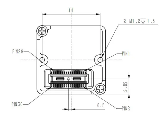
For the SuperMini 640 / 640T bare core, plan all three supply rails: MAIN_POWER 3.8–5.2 V (typically 5 V), +3.3 V at 3.28–3.32 V, and +1.8 V at 1.78–1.82 V. UART uses 1.8 V logic, with TX/RX defined from the core. Follow the connector and pin definitions on PDF pages 6–7 and the noise limits and power-on timing on PDF page 8; these requirements apply to the bare-core connector, not an optional expansion-board input.
2.2 Gimbal Control & Telemetry: UART, MAVLink, and S.Bus Integration
Synchronization between an autopilot, gimbal controller, and thermal core requires a defined control architecture. Match each device’s protocol, serial voltage, baud rate, and command set. A core’s UART control port does not itself establish MAVLink, CAN, or S.Bus compatibility; the payload controller may need to translate commands and coordinate image capture with recorded attitude and position.
For an implemented MAVLink payload, use the supported gimbal and camera services to manage orientation, region-of-interest control, and capture requests. The MAVLink Gimbal Protocol v2 separates the gimbal manager from the device and provides capability discovery. Palette, focus, and radiometric capture controls still require supported camera commands or a translation layer. If S.Bus or PWM is used for operator control, validate channel mapping, control priority, loss-of-link behavior, and timestamps in the complete system.
2.3 Embedded Processing & Edge AI with Onboard Companion Computers
Onboard edge processing can help prioritize thermal anomalies during inspection while retaining recorded data for later review. Choose an input format the camera actually supplies, implement host capture and decoding, and validate the model against representative imagery and known targets. Temperature-based thresholds require calibrated temperature data; a contrast-enhanced image supports a different analysis path. Measure processing load, frame drops, latency, and thermal throttling, and synchronize camera frames with position and attitude before generating geo-tagged alerts.
3. Radiometric Data Pipelines, NUC Calibration, and Metrology
Translating minute resistance shifts in a microbolometer array into stable, calibrated, absolute temperature data during aggressive flight profiles requires robust metrology and active sensor compensation.
3.1 Qualitative Thermal Imaging vs. Calibrated Radiometry
Payload builders must understand the core distinction between qualitative viewing and metrology-grade radiometry:
- 📌 Qualitative (Non-Radiometric) Cores: These cameras provide thermal contrast for observation and scene interpretation. Automatic gain control and detail enhancement can make targets easier to see, but displayed brightness alone is not a calibrated temperature reading. Confirm the delivered image format and processing controls for the selected model; use a documented radiometric data path when the inspection requires temperature values.
- 📌 Quantitative (Calibrated Radiometric) Cores: These systems provide a manufacturer-defined conversion from measured signal to temperature within specified ranges and conditions. Transport bit depth and a RAW label do not establish calibration or a universal linear radiance-to-temperature relationship. For SuperMini 640T, decode its documented temperature words and apply the formula for the actual output mode. Quantitative inspections also require appropriate target fill, focus, emissivity, reflected apparent temperature, and atmospheric or window compensation, as applicable to the complete system.
3.2 Non-Uniformity Correction (NUC): Mechanical Shutter vs. Shutterless Algorithms
Because microbolometer pixels exhibit slight variations in individual gain and offset response, uncooled FPAs suffer from fixed-pattern noise (FPN) that drifts over time and shifts with changing ambient temperatures.
- 🛠️ Mechanical Shutter NUC: In shutter-equipped cameras, an internal reference can be used to update detector correction while the scene image pauses. Duration, trigger conditions, and control access are model-specific. Identify correction events in captured data and verify how the tracking or inspection application handles them. An offset correction supports image stability; it does not replace the system’s temperature calibration and measurement checks.
- 🛠️ Scene-Based Shutterless Algorithms (SBNUC): Some cameras estimate non-uniformity from scene information to reduce reliance on shutter events. Performance depends on the algorithm, scene content, and motion. Verify residual artifacts and drift across representative flight imagery, and obtain the selected camera’s correction and radiometry documentation before planning uninterrupted quantitative capture.
3.3 Temperature Drift Mitigation in High-Altitude Aerial Envelopes
Payload temperature can change with camera self-heating, sunlight, ambient conditions, and propeller airflow. Allow the configured camera to stabilize and test temperature readings across the intended environment with the final lens, window, enclosure, and heat path. SuperMini 640T lists typical accuracy of ±2°C or ±2% of reading at ambient −20°C to +60°C, within its specified measurement ranges. The broader core operating range does not extend those thermography conditions. Record correction events and compare against a suitable temperature reference during qualification.
4. 3-Axis Gimbal Mechanics, Vibration Isolation, and Aerodynamics
High-resolution infrared optics on a dynamic multirotor platform are vulnerable to frame chatter, motor resonance, and aerodynamic buffeting. Preserving your optical modulation transfer function (MTF) downrange requires dialed-in stabilization mechanics.
4.1 Resonant Frequencies and Damper Durometer Matching
Motor, propeller, and structural vibration can blur thermal imagery and reduce the usable detail relative to the calculated GSD. Measure the actual excitation spectrum across the intended motor speeds and maneuvers, then choose isolators for the payload mass, center of gravity, and motion clearance. Verify the combined mount and gimbal response with the selected lens and cable routing.
For a simplified single-degree-of-freedom mass-spring model, the natural frequency (fn) is:
fn = (1 / 2π) × √(k / m)
Here k is the effective spring rate in N/m and m is the suspended mass in kg, giving fn in Hz. Shore hardness alone does not specify spring rate. Use the mount’s load-deflection and damping data to place its resonance below the dominant excitation while allowing adequate maneuver and shock travel. Check for amplification near resonance and coupled rotational modes in the assembled gimbal.
4.2 Ingress Protection and Electromagnetic Interference (EMI) Shielding
Specify enclosure protection for the expected dust, water, condensation, and temperature exposure, and verify any claimed IP rating on the complete assembled payload. Seals, an appropriate LWIR window, and a pressure-equalizing vent are design choices that also affect heat flow and optical transmission. Treat motor drives, switching converters, and wiring as potential EMI sources. Plan grounding, shielding, filtering, and cable routing, then check image quality and data integrity during operation of the aircraft electronics.
5. OEM Cores and Ground Verification for a Thermographic Camera Drone
Selecting the right thermal engine comes down to matching sensor pitch, frame rate, and optical packages to the mission profile. For custom drone integration and payload prototyping, OEM cores require matched optics, interface electronics, power, host processing, display or recording, operator controls, and a protective enclosure to become complete field instruments. Quantitative ground verification also requires a calibrated radiometric instrument and a documented measurement procedure. To inspect bare sensor cores and OEM modules, check out the CAMCUDA thermal modules catalogue.
The following OEM examples serve different roles: the configured SuperMini 640T provides a thermographic integration path, while the AeroMini 640 non-radiometric configuration supports qualitative thermal observation:
CAMCUDA SuperMini 640T — 30 Hz Thermographic OEM Core
An 8 µm, 640 × 512 core for custom thermographic UAV payloads and instrument development.
The SuperMini 640T is the 30 Hz thermographic member of the SuperMini family. The separate SuperMini 640 is a 50 Hz imaging-only model. The 640T publishes CDS3 and MIPI temperature-data paths; host parsing, the selected optics and interface, and the calibration workflow must be validated for the assembled payload. This configuration is supplied through configuration review and project quotation.
| Parameter | Specification / Configuration |
|---|---|
| Thermal Resolution | 640 × 512 |
| Pixel Pitch / NETD | 8 µm / ≤ 40 mK at 25°C, F1.0 |
| Lens Options | 3.7 / 6.1 / 8.7 / 11 mm, F1.0 athermal |
| Thermographic Frame Rate | 30 Hz (SuperMini 640T) |
| Measurement Ranges / Typical Accuracy | −20°C to +150°C and +100°C to +650°C; typical ±2°C or ±2% of reading at ambient −20°C to +60°C |
| Typical Core Power | ≤ 0.5 W at 25°C, excluding expansion board |
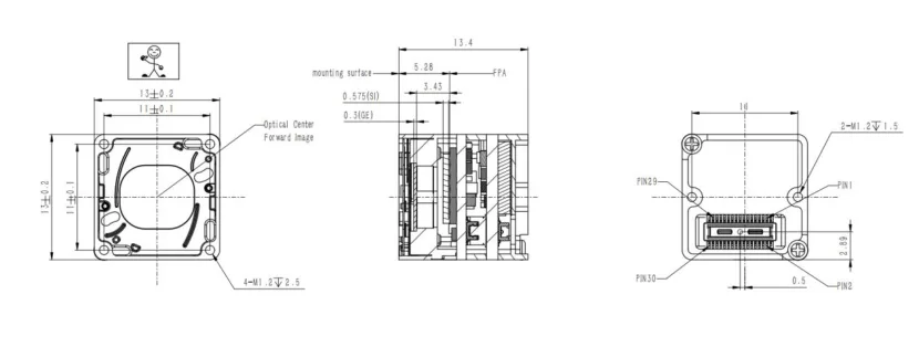
| Physical Dimensions | 13 × 13 × 13.4 mm, excluding optics and expansion boards |
| Core Weight | <3.5 g, excluding optics and expansion boards |
Primary Application Profile: For quantitative ground verification after an aerial survey, use a calibrated radiometric field instrument or suitable reference measurement on the same target under comparable load and ambient conditions. Document emissivity, reflected temperature, working distance and target fill; validate the completed 640T assembly and its temperature-data processing before using it for reported measurements.
CAMCUDA AeroMini 640 — 9 mm Non-Radiometric OEM Module
Qualitative thermal observation for UAV payload evaluation and field situational awareness.
This 640 × 512, 12 µm VOx module is shown in the 9 mm non-radiometric configuration, with 60 Hz as the factory default and an optional 30 Hz factory configuration. It does not measure temperature. Match the interface board and host software to the ordered assembly; the separate 25 Hz radiometric version is currently out of stock and available by enquiry only.
| Parameter | Specification / Configuration |
|---|---|
| Sensor Technology | VOx Uncooled Sensor (8–14 µm Spectral Range) |
| Resolution / Pixel Pitch | 640 × 512 / 12 µm |
| Frame Rate | 60 Hz factory default / 30 Hz factory option; non-radiometric |
| Selected Lens / FOV | 9 mm, F1.0 / 48.7° × 38.6° |
| Thermal Sensitivity (NETD) | ≤ 30 mK at 25°C, F1.0 |
| Module Size / Weight | 21 × 21 × 28 mm / <20 g, both excluding lens and flange |
Primary Application Profile: Integrate this module into a complete UAV or portable field system for scene assessment, search support, patrol and documentation. Its non-radiometric imagery can help relocate or contextualize an aerial anomaly. Temperature reporting requires a calibrated radiometric measurement; confirm suspected defects through the appropriate field inspection.
For this AeroMini module, use the AeroMini datasheet and AeroMini Linux, examples and SDK FAQ. Confirm the ordered board, firmware, host, output format and frame rate; these resources do not establish SuperMini SDK support.
6. OEM Sourcing, Supply Chain Verification, and Regulatory Compliance
Engineering a commercial thermal payload isn’t just about optics and code—it requires navigating international trade restrictions, supply chain traceability audits, and regulatory certifications.
6.1 Export Controls: Frame Rate Limits and the Wassenaar Arrangement
The Wassenaar Arrangement provides control lists implemented through national rules. Before ordering, request the supplier’s current classification and review the exact core, firmware, destination, end user, and end use. Frame rate alone does not determine an ECCN or licensing outcome; 9 Hz or slower is not a blanket exemption. For transactions subject to U.S. EAR rules, consult BIS classification guidance and applicable camera end-use and end-user controls. Agree the required supporting documents and review lead time with the supplier before shipment.
6.2 Regulatory Directives and NDAA Section 889 Compliance
For contracts invoking NDAA Section 889, review manufacturer identities and the supplied equipment or services against the contract’s applicable requirements, including FAR 52.204-25 where relevant. Country of origin or a generic compliance label alone does not establish the result. For an EU-bound product, identify the applicable product rules and request model-specific declarations and supporting records for the final configuration. The CAMCUDA EU Compliance Documentation is a starting point for that document review; obtain confirmation of scope for the ordered hardware.
6.3 Factory Boresighting and Optical Axis Alignment
For dual-sensor payloads combining LWIR and visible or low-light cameras, define the required alignment accuracy and working-distance range. Lens distortion, relative camera orientation, and the separation between the viewpoints affect image registration; even aligned optical axes can retain distance-dependent parallax. Request the assembly’s calibration procedure and usable calibration data, and verify overlays across the intended distances and temperatures. Confirm whether alignment is implemented in the payload controller or camera firmware and how it is maintained after servicing.
7. Frequently Asked Engineering Questions (Deep-Dive FAQ)
How can engineering teams integrate a thermal camera into lightweight or sub-250g drones without exceeding SWaP limits?
What communication protocols and video interfaces are optimal for custom drone thermal payloads?
1. Pilot Viewing: Use a documented video output and compatible downlink, then measure sensor-to-display latency and behavior during dropped or paused frames.
2. Embedded Processing: Match the core’s packet type, lane configuration, byte order, frame layout, and driver requirements. SuperMini 640T’s MIPI path carries RAW8 bytes reassembled into 16-bit image and temperature words; USB capability depends on the chosen interface board and host support.
3. Gimbal and Camera Control: Use supported command protocols or a validated translation layer between autopilot, gimbal controller, and core. Confirm logic levels, control priority, capture timing, and recorded position and attitude.
Do commercial drone inspection workflows strictly require a radiometric thermal camera?
What optical lens material is required for long-wave infrared (LWIR) drone payloads?
How does sensor resolution (384×288 vs 640×512) affect flight efficiency during aerial surveys?
📚 References & Further Reading
- Industry Standard: A3 Camera Link Standard | A3 Vision Standards
- Related Guide: Explore CAMCUDA’s dedicated Thermal Sensor Modules Category for direct OEM integrations.
- Compliance Documents: Start a configuration-specific document review with the CAMCUDA EU Compliance Portal.