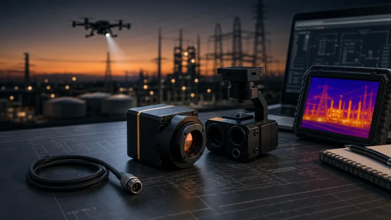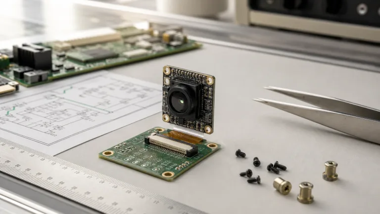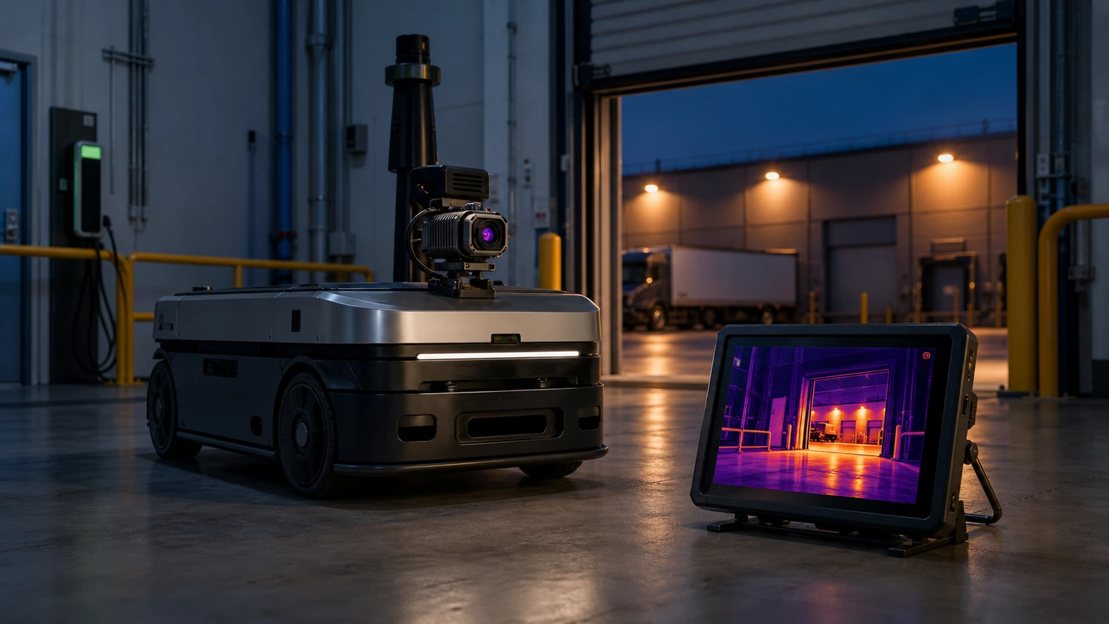
camera cores: 4 Practical Questions Before You Add Thermal to a Safer Mobile Robot Stack
camera cores become much harder to compare once a robotics team decides thermal should join an otherwise visible-light stack. The detector is only one decision. The real questions are where thermal imagery adds useful context after validation, how the image reaches the host and the service team, and whether procurement asked for the right documents before the pilot moves out of the lab.
This article uses CAMCUDA AeroMini 640 as the concrete product example: a non-radiometric 640 × 512 LWIR core, with a 9 mm lens and USB + CVBS + MIPI board as the starting configuration. The goal is to help a buyer decide whether a compact thermal module belongs in the mobile robot stack before the pilot collects avoidable rework. Its role here is qualitative image review after application validation. This thermal add-on does not replace existing navigation or safety systems, and no safety certification, collision-avoidance function, or autonomous navigation capability is established.
Technical author: Daniel · Hardware Support
Sales contributors: Vivian, Lena and Sophie
Quick answer
If your team is comparing camera cores for a mobile robot, confirm four things before ordering the second sample: the thermal job to be done, the host and review path, the mechanical envelope, and the procurement packet. For CAMCUDA buyers, AeroMini 640 offers non-radiometric imaging at a 60 Hz factory default or 30 Hz factory option. Select the board deliberately: USB + CVBS + MIPI and Type-C + CVBS are different packages. Confirm interface details, service-monitor expectations, matched support files, and which NDAA-related documents are available for the exact configuration during RFQ.
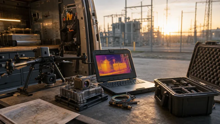
camera cores selection chart for a mobile robot thermal stack
The right way to compare camera cores is to start with the operational bottleneck rather than the prettiest thermal image. In many robotics projects, thermal is introduced after the visible stack already exists, which means the winning module is the one that fits the current robot workflow with the least ambiguity.
| Decision area | What to confirm | Why it matters before the pilot |
|---|---|---|
| What does thermal need to reveal? | Whether imagery adds useful context around motors, charging hardware, dock-door areas, or people in the scene, under the proposed conditions | These are questions to assess in an imaging trial, not promises of measured temperature, overheating alarms, or dependable human detection |
| Where will the image go first? | Edge processor, engineering laptop, service tablet, or a commissioning monitor | This decides whether USB alone is enough or whether the review path needs more planning |
| How crowded is the sensor stack? | Complete mounting envelope, lens clearance, cable routing, weight, and power margin | Compact camera cores still create late work if the robot enclosure or harness path was only assumed |
| Who owns integration after the first demo? | Robot OEM, systems integrator, field service team, or procurement | Ownership gaps are where a successful bench test becomes a delayed pilot |
| What documents are required for scaling? | Matched interface references, drawings, environmental limits, and available CE/RoHS or NDAA-related documents for buyer review | The module choice is not ready for purchasing if the paperwork path is still vague |
NVIDIA’s manufacturing coverage and Micron’s account of AI in its own factories provide broader examples of technology being integrated into industrial systems. The practical lesson for this thermal pilot is to define the surrounding workflow and its acceptance criteria. Those sources do not establish AeroMini AI features, host compatibility, or a manufacturing performance result.
Why thermal gets added too late in mobile robot pilots
Many robotics teams do not begin with a thermal requirement. They begin with visible cameras, a navigation stack, and a narrow mission. Thermal enters the conversation later, usually after someone asks whether it could add context in a night loading zone, around cold-start machinery, or during service review of equipment. That is a sensible trigger, but it also means thermal arrives after architecture decisions are already half-frozen. The proposed observation still needs testing under the actual scene and viewing conditions.
The consequence is predictable. The engineering team proves the concept over USB on a bench. Operations asks for a simple live view at the dock or maintenance bay. Procurement asks for drawings and compliance-related materials before approving the next quantity. Suddenly the discussion about camera cores is no longer about image quality alone. It is about wiring, service workflow, sample timing, and how much of the robot stack must change to carry one more sensor cleanly.
That is where buyers benefit from a more disciplined question set. Instead of asking whether thermal is useful in general, ask where it reduces uncertainty in the robot’s actual job. If the robot only needs commissioning-time qualitative image review of motors or charging points, the review path matters differently than if thermal feeds a separately validated edge model. If a service monitor still exists in the workflow, the RFQ needs to surface that early rather than rely on a vague promise to sort the display path out later. This non-radiometric example supplies no calibrated temperature values or temperature-threshold alarms.
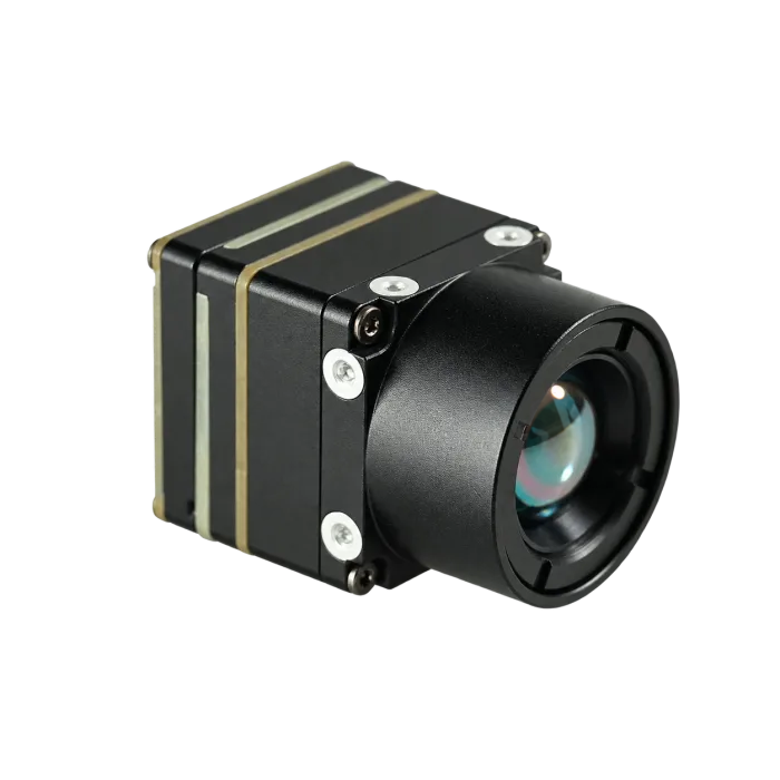
AeroMini 640 parameter table for camera cores buyers
The following values come from the AeroMini 640 product page and its matched documentation. If your team is comparing camera cores for a thermal add-on path, match these published details against the robot host, service workflow, and RFQ requirements. The evaluation example is non-radiometric imaging with a 9 mm lens and USB + CVBS + MIPI board.
| Detector | |
|---|---|
| Component model | CAMCUDA AeroMini 640, non-radiometric imaging; 9 mm evaluation example |
| Detector type | Uncooled vanadium oxide (VOx) infrared detector |
| Resolution | 640 × 512 |
| Pixel pitch | 12 μm |
| Spectral range | 8–14 μm |
| Detector frame rate | 60 Hz factory default / 30 Hz factory option for the non-radiometric version; verify the selected output and host timing |
| NETD | ≤30 mK at 25°C, F/1.0; sensitivity, not absolute temperature accuracy |
| Image adjustment | |
| Brightness / contrast / enhancement | Request supported controls and adjustment ranges for the supplied firmware and PC software |
| Image polarity / palettes | White hot / Black hot; confirm any additional palettes for the selected firmware |
| Image processing | |
| Functions | Supported NUC/FFC settings, such as automatic triggering behavior, can be adjusted through PC software according to the operating environment. Confirm whether other filtering, detail enhancement, or histogram controls are supported, then request their commands if available. |
| Power and interface | |
| Supply voltage | 5 V at the illustrated 16-pin POWER_IN1 and 26-pin POWER_IN2 inputs; do not connect either input to 12 V. Use the matched guide for the selected board. |
| Typical power consumption | <0.5 W typical at 25°C for the module; complete-kit and host consumption may differ |
| Digital video | USB and MIPI on the selected USB + CVBS + MIPI board; Type-C + CVBS is a separate package. Confirm format, host compatibility, and output rate. |
| Communication interface | Illustrated 16-pin reference: RS232 RX/TX; 26-pin reference: UART TX/RX. Match the board, signal levels, transceiver, and command protocol; USB video alone does not establish USB serial or an RS422 connection. |
| Analog video support | CVBS, PAL/NTSC, on the applicable selected board; confirm the mode, cable, receiving equipment, and actual timing |
| Mechanical | |
| Weight | <20 g excluding lens and flange; confirm complete assembly mass |
| Dimensions | 21 × 21 × 28 mm excluding lens and flange; request the selected lens/board assembly envelope |
| Environmental adaptability | |
| Operating temperature | −40°C to +80°C |
| Storage temperature | −50°C to +85°C |
| Humidity | 5–95%, non-condensing |
| Vibration | Request the selected assembly’s vibration test profile and report, including mounting conditions |
| Shock | Request the selected assembly’s shock test profile and report, including mounting conditions |
Those numbers are useful because they turn a broad camera cores search into a stack-fit review. A module with known dimensions, weight, environmental limits, and published interface language is easier to route into a robot bill of materials and review with field-service teams. The quoted dimensions and mass exclude the lens and flange; add the board, cable, bracket, and enclosure, and check complete-system power. Temperature and humidity limits do not establish weatherproofing, an IP rating, or a completed shock or vibration qualification. The public AeroMini datasheet supplies electrical references; request a dimensioned drawing for the selected complete assembly.
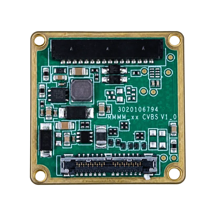
Application case: a loading-bay robot that needs thermal without a full redesign
Buyer moment
In this illustrative planning scenario, a warehouse automation team has a compact mobile robot that already uses visible cameras for navigation and barcode or obstacle work. The next pilot asks whether thermal imagery can support dock-door review and a service routine around charging hardware and drivetrain surfaces. The team does not want a heavyweight thermal payload program. It wants a small thermal view for an operator to evaluate near dawn, dusk, or in mixed indoor-outdoor transitions, with the observation conditions and limitations recorded.
This is a better use case for camera cores than a generic “thermal is good for robots” statement. The buyer can name the mission, the service constraint, and the practical trade-off. The robot needs something compact enough not to punish weight and cable routing, but useful enough to justify one more input path and one more RFQ line item.
The common mistake here is to prove the thermal view once on a development laptop and assume the stack question is finished. It is not. The service team may still want a simple live monitor during commissioning. The mechanical team may need the connector direction confirmed before the bracket is frozen. Procurement may need interface references, environmental limits, or an NDAA statement request before the next lot is approved. In that moment, the best thermal candidate among the available camera cores is the one with the fewest hidden assumptions.
That is why AeroMini 640 is a practical evaluation example. It gives the team a compact 640 × 512 LWIR module path with lens and board choices to match to the host and service workflow. Test startup and reconnect behavior, the actual viewing delay, and NUC/FFC behavior under representative conditions. Dock transitions also need enclosure and condensation planning. The sample provides a way to assess qualitative imagery, not a calibrated overheating diagnosis or a temperature-based pass/fail decision.
Interface planning: USB validation, matched serial control, and the CVBS review path
The interface question is usually where camera cores conversations become either honest or expensive. AeroMini’s USB + CVBS + MIPI board and Type-C + CVBS board are distinct choices. If MIPI is part of the intended robot host design, specify the host, required output format, firmware, and rate in the RFQ and validate the delivered combination. The presence of USB video does not establish a USB virtual serial port or an RS422 control connection.
The illustrated 16-pin electrical reference names RS232 RX/TX, while the 26-pin reference names UART TX/RX. Match the connector revision, electrical levels, required transceiver, and command protocol before wiring a robot controller. In the matched datasheet signal tables, 16-pin POWER_IN1 and 26-pin POWER_IN2 are 5 V inputs: do not apply 12 V to either, even though the product family’s general table mentions board-dependent 5 V or 12 V supplies. Neither of these connector references replaces the Type-C board’s own guide.
The next question is whether the image is only for engineering or whether operations also needs a simple human review path. Some robotics teams still keep a monitor or recorder around commissioning. If that is true for your build, say it early: specify the selected board’s CVBS mode, PAL/NTSC requirement, cable, receiving equipment, and acceptable observed delay. CVBS is an analog path, separate from USB/MIPI digital video. A 60 Hz factory configuration does not guarantee simultaneous 60 Hz on every output or a particular end-to-end viewing latency. Validate the actual paths that will be used together.
LightPath’s OEM integration writing treats a thermal camera as one part of a larger platform decision around interfaces and validation steps. Robotics buyers should use the same discipline. If the pilot stack includes a host PC now, a service screen later, and another control method in the production robot, the RFQ should say so in plain language instead of hiding the problem inside a vague request for “integration support.” LightPath’s product capabilities are not specifications for AeroMini.

For teams still evaluating whether thermal will remain a commissioning aid or become a permanent analytics input, keeping the first RFQ honest is more valuable than pretending the path is final. A thermal core that is easy to bench over USB but hard to explain to service or procurement will slow the project down later.
Request the configuration-matched manual, serial commands, and development resources through the AeroMini Linux drivers, examples, and SDK FAQ. Record the delivered firmware version, supported controls, host software, and tested output settings. Supported NUC/FFC settings such as automatic triggering can be adjusted through PC software according to the environment; confirm whether other requested processing controls exist before asking how to configure them. Resource availability alone does not demonstrate integration with the robot’s host.
Common mistakes when comparing camera cores for robotics
1. Adding thermal after the mechanical stack is already frozen
Small camera cores still need connector space, cable routing, and a realistic mount. Late thermal additions usually hurt the bracket and harness first.
2. Treating the first USB image as proof of deployment readiness
A bench-friendly USB path does not automatically validate the final service workflow, robot host board, or field-monitor expectations.
3. Assuming analog is either obsolete or automatic
Some mobile robot programs never need it. Others still want a simple live view during setup or troubleshooting. Confirm the real workflow and any viewing-delay requirement before closing the interface discussion.
4. Asking procurement to step in after engineering has already picked the module
By then the buyer may still be missing drawings, environmental limits, interface references, or documentation timing for site approval.
5. Comparing camera cores without naming the missed-context problem
If the team cannot explain what thermal reveals that the visible stack misses, the project is not ready for a clean RFQ yet.
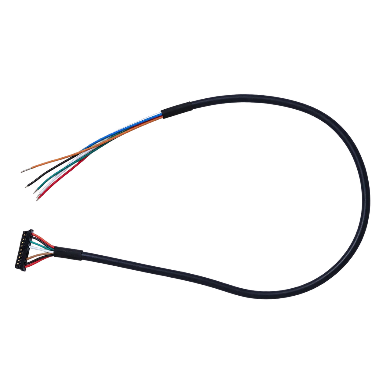
RFQ checklist for camera cores buyers in Europe and North America
The fastest way to move from evaluation to a serious sample discussion is to send an RFQ that removes uncertainty. For camera cores in a mobile robot thermal project, the useful checklist is short and specific.
| RFQ item | What to send |
|---|---|
| Mission summary | State the qualitative image-review question, target areas, distances, conditions, and acceptance criteria. For any non-identifying human-presence review, specify target size/range, occlusion and motion conditions, and human validation. Identify any separate proposal for analytics or temperature measurement. |
| Host and software path | State whether the thermal image feeds a host PC, embedded processor, service tool, or mixed review path; include OS, required video format/rate, firmware and matched SDK requests |
| Mechanical limits | Include space claim, weight concern, connector direction, bracket concept, and cable route; request the complete lens/board assembly drawing or matched CAD |
| Interface expectation | Select USB + CVBS + MIPI or Type-C + CVBS; confirm board input voltage, serial levels/transceiver/protocol, wiring, and any CVBS monitor/recorder chain |
| Environment | Provide operating temperature, vibration concern, humidity concern, and indoor-outdoor transition notes; include enclosure/condensation needs and request applicable assembly test profiles and reports |
| Documentation package | Request matched electrical/mechanical references, firmware and support resources, and available CE/RoHS or NDAA-related documents for the exact configuration, destination, and buyer review |
For a preliminary view of working distance and field width, use the thermal imaging calculator, then validate the actual lens and target in representative conditions; a geometry estimate is not a dependable human-detection or safety range.
If your team is still exploring options, start with CAMCUDA’s thermal imaging cores category, the broader thermal modules category, and the applications hub. If the robot concept is already defined, use the support downloads, the FAQ page, and the CAMCUDA contact / RFQ page to make the first request more precise.
Raise documentation timing early when formal purchasing review is part of the project. Ask what NDAA-related and other requested materials are available for the exact AeroMini configuration, destination, and use case, and have the buyer’s team review their scope and relevance. A general product statement is not a finding of eligibility or compliance for the robot project.
Compare the AeroMini path against your robot workflow before the pilot hardens
If your next project phase is to add thermal without rebuilding the whole robot stack, start by reviewing the AeroMini 640 product page and compare it with the wider thermal imaging cores lineup. Then send an RFQ that includes the host path, service workflow, mounting envelope, and documentation needs. That helps you assess whether this thermal option fits your stack before thermal turns into a late integration problem.
For application context, see the outdoor and field thermal imaging page and the wider applications pages. If your team already knows the use case and interface, move directly to support downloads and contact / RFQ.
FAQ
What does camera cores mean in this article?
Here, camera cores means the module-level imaging building blocks a robotics team compares when adding another sensing path. The thermal module is one core in a larger robot stack that may already include visible cameras and other sensors.
Why would a mobile robot add a thermal core after the visible system already works?
To assess whether it adds useful context under low-light, glare, cold-start, or other conditions that matter for the proposed service or anomaly-review task. Thermal is often added to solve that specific gap rather than to replace the whole stack. Validate the scene and viewing conditions; this non-radiometric example does not measure temperature.
Is USB enough for every camera cores thermal evaluation?
No. USB is often the easiest validation path, but some projects also need a clearer control method, a service monitor, or another review path that must be named early.
When should I ask about CVBS analog output?
Ask when the workflow includes a service monitor, recorder, or other analog viewing equipment. Confirm the selected board, PAL/NTSC mode, cable, receiver, and actual viewing delay. The 60 Hz factory imaging configuration does not guarantee simultaneous 60 Hz on every output.
What makes AeroMini 640 relevant for robotics buyers?
It offers a 640 × 512 non-radiometric LWIR imaging option with published core specifications and selectable lens and interface packages. Those choices make a concrete evaluation possible, but robot suitability must be established with the selected assembly. Dimensions and mass exclude the lens and flange, and typical module power is not a complete-kit power figure.
Do camera cores buyers need to ask about NDAA at the sample stage?
If the purchasing process requires that review, ask early which NDAA-related documents are available for the exact AeroMini configuration, destination, and use case. The buyer’s team should assess their scope and relevance; requesting a statement does not establish project eligibility.
What should procurement send with the first RFQ?
Send the robot mission summary, host platform, preferred interface, mechanical limits, environmental notes, service-monitor expectations, quantity plan, and document requests.
Can one thermal module work for both robotics and UAV projects?
Sometimes yes, but the same core still lives inside different mechanical, interface, and documentation workflows. CAMCUDA buyers should confirm the exact use case during RFQ rather than assume one stack maps cleanly to another.
What CAMCUDA pages should I review next?
Start with the AeroMini 640 product page, then review the broader thermal imaging cores category, applications hub, and RFQ contact page. Ask for documentation matched to the lens, board, and firmware you intend to evaluate.
For broader industry context, see NVIDIA’s manufacturing AI coverage, Micron’s account of manufacturing AI at enterprise scale, and LightPath’s OEM thermal integration article. These sources provide context on industrial systems and OEM integration planning. They do not establish AeroMini AI or Jetson support, yield improvements, temperature measurement, or robot safety capabilities. Use the matched CAMCUDA product documents and application tests for the actual selection.