Night Vision Drones: OEM Thermal Imaging Payload & Integration Guide
Night Vision Drones: OEM Thermal Imaging Payload & Integration Guide
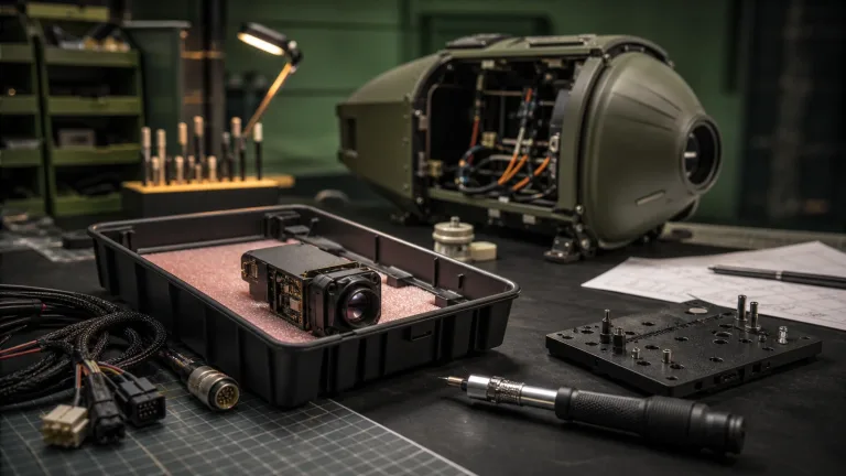
The rapid shift toward autonomous unmanned aerial vehicles (UAVs) across defense, utility inspection, border security, and search-and-rescue (SAR) has completely changed what we expect from aerial night vision. If you want true tactical and commercial performance in zero-lux conditions, bad weather, or heavy obscurants, consumer-grade optical sensors and illuminated CMOS chips just won’t cut it. Modern high-performance night vision drones rely on rugged electro-optical and infrared (EO/IR) payload architectures that balance Size, Weight, Power, and Cost (SWaP-C) while delivering actionable intelligence from safe standoff distances.
Building an aerial platform that can cut through thick fog, wildfire smoke, dense tree canopies, and industrial dust requires a no-nonsense systems-engineering approach. You have to balance uncooled Long-Wave Infrared (LWIR) focal plane arrays (FPAs), high-magnification visible/near-infrared (NIR) sensors, laser rangefinding (LRF) telemetry, and ultra-low-latency onboard video pipelines. This guide breaks down the mechanical, optical, and electrical engineering needed to design reliable night vision drone payloads—covering detector physics, Johnson’s criteria lens sizing, sensor fusion, and field-tested OEM integration workflows.
Table of Contents
- 👉 1. Core Physics: LWIR Thermal vs. Digital NIR in Drone Payloads
- 👉 2. SWaP-C Optimization in Aerial Gimbal Design
- 👉 3. Optics and Johnson’s Criteria for Aerial DRI Calculations
- 👉 4. Multi-Sensor Synergy: Thermal Cores & Laser Rangefinders
- 👉 5. Electrical & Protocol Integration: MIPI, USB UVC, and CVBS
- 👉 6. Commercial OEM Hardware Specifications & Comparison
- 👉 7. Aerial Payload Integration Checklist
- 👉 8. Deep-Dive Integration FAQ
1. Core Physics: LWIR Thermal vs. Digital NIR in Drone Payloads
When you sit down to architect an aerial night-vision payload, you are dealing with two fundamentally different physical regimes: active/ambient digital night vision (operating across the visible-to-near-infrared band, 0.4 to 1.1 µm) and passive thermal imaging (operating in the long-wave infrared band, 8 to 14 µm). Choosing the right band defines your airframe’s operating envelope, environmental survivability, and tactical signature.
Digital night-vision systems use high-gain silicon CMOS detectors tuned for maximum quantum efficiency in the near-infrared (NIR) spectrum. These sensors amplify tiny amounts of ambient starlight or moonlight. While digital low-light CMOS sensors give you crisp spatial resolution (like 1080p or 4K) at a modest bill of materials (BOM) cost, they drop off a cliff when ambient illuminance dips below 0.001 lux. To work in total darkness, digital NIR systems need active infrared illumination (typically 850 nm or 940 nm LEDs or VCSEL laser diodes).
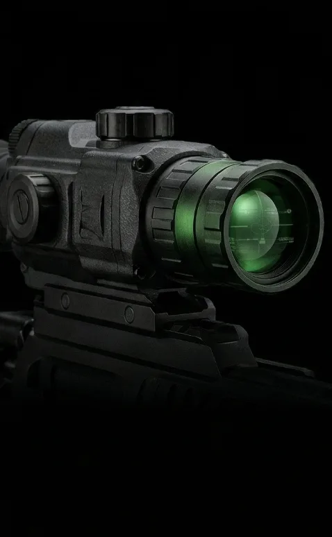
Here’s the deal with active illumination: on an airborne platform, it creates severe engineering headaches. First, it pulls significant parasitic battery power (3 to 10 W per emitter), cutting right into your flight endurance. Second, it acts as an optical beacon to anyone on the ground with standard night vision gear. Third, you run straight into the inverse-square law: optical irradiance decays exponentially with slant range, making high-altitude illumination impractical.
Passive Long-Wave Infrared (LWIR) sensors, on the other hand, operate on pure blackbody physics—governed by Planck’s Radiation Law and the Stefan-Boltzmann Law ($W = \epsilon \sigma T^4$). Every physical object above absolute zero emits electromagnetic radiation based on its surface temperature and material emissivity ($\epsilon$). Modern uncooled Vanadium Oxide (VOx) focal plane arrays measure minute differences in emitted thermal energy ($\Delta T$) across the 8–14 µm atmospheric transmission window without a single photon of ambient light.
Look at how light travels through the air. Rayleigh scattering heavily attenuates visible and NIR wavelengths when flying through light fog, brushfire smoke, marine haze, or dust. Because LWIR wavelengths (8–14 µm) are an order of magnitude longer than visible light (0.4–0.7 µm), thermal radiation passes straight through airborne particles with minimal scattering. For unmanned platforms engineered by industry leaders like Autel Robotics and thermal specialists like Sierra-Olympic Technologies, uncooled VOx thermal cores remain the go-to standard for zero-lux navigation and autonomous target tracking.
2. SWaP-C Optimization in Aerial Gimbal Design
In the drone world, Size, Weight, Power, and Cost (SWaP-C) govern every single engineering decision. Whether you are building a multirotor, a fixed-wing scout, or a hybrid VTOL, every single gram added to the nose or belly degrades hover stability, strains the motors, cuts into battery reserves, and drives up the rotational inertia of your multi-axis brushless gimbal.
High-performance gimbal stabilization relies on closed-loop proportional-integral-derivative (PID) controllers running anywhere between 500 Hz and 2 kHz. The payload’s rotational inertia ($I$) is defined by:
$$I = \sum m_i r_i^2$$
Where $m_i$ represents the mass of each payload component and $r_i$ is its radial distance from the pivot axis. When you select an oversized, heavy thermal core, that extra inertia forces the brushless direct-drive motors to draw more peak current. That extra torque demand introduces mechanical resonance, heats up the gimbal windings, and degrades stabilization accuracy when fighting turbulent crosswinds.
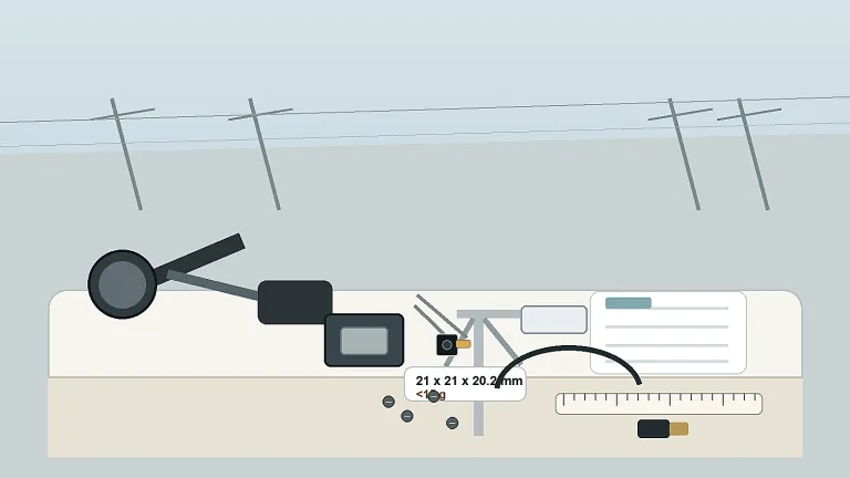
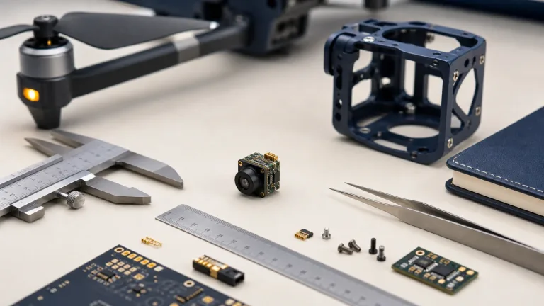
Managing heat inside the gimbal housing is just as critical. Uncooled VOx thermal modules generate continuous internal heat from the Readout Integrated Circuit (ROIC) and onboard FPGA image processing. Because microbolometers measure microscopic temperature changes across suspended pixel membranes, internal thermal drift creates fixed-pattern noise and non-uniformity across the video feed. Ultra-compact modules like the CAMCUDA FlexMini 640 solve this by stripping bare-chassis weight down to just 23.1 g while pulling less than 0.7 W in full 50 Hz operation. That ultra-low power draw allows you to use lightweight, passively cooled 6061-T6 aluminum or magnesium housings without heavy, failure-prone cooling fans.
Power distribution is another area where builds often run into trouble. Fast motor throttling on multirotors dumps aggressive inductive noise and voltage ripples into the DC bus. Thermal modules designed with rigid, narrow voltage limits (like 3.3 V or 5.0 V ±2%) force you to add dedicated, shielded low-dropout (LDO) regulators or isolated DC-DC converters to avoid horizontal video banding and digital lockups. Choosing modules with a broad 5–24 V DC input range lets you power the core straight from the gimbal slip ring or intermediate 12 V rail without extra filtering hardware. For a deep dive into microbolometer layouts and chassis thermal sinks, check out our high-resolution thermal imaging camera OEM selection guide.
3. Optics and Johnson’s Criteria for Aerial DRI Calculations
Choosing the right thermal lens is all about trading Field of View (FOV) for target standoff distance. In the shop, we quantify target performance using Johnson’s Criteria, which defines the minimum number of pixels (or line pairs) needed across a target’s critical dimension to achieve three distinct tactical thresholds:
- 🔍 Detection (1.5 pixels on target / 0.75 line pairs): The operator or edge AI algorithm can spot a distinct signature against background clutter.
- 🔍 Recognition (6.0 pixels on target / 3.0 line pairs): The operator can distinguish the target’s general class (e.g., separating a human from a deer, or a passenger car from an armored vehicle).
- 🔍 Identification (12.0 pixels on target / 6.0 line pairs): The operator can make out fine details (e.g., personal equipment, structural damage, open vehicle hatches, or body posture).
The spatial resolving power of any thermal camera comes down to its Instantaneous Field of View (IFOV), expressed in milliradians (mrad):
$$\text{IFOV} = \frac{d}{f}$$
Where $d$ is the pixel pitch ($12\ \mu\text{m} = 0.012\ \text{mm}$) and $f$ is the lens focal length in millimeters. Ground target resolution at a given slant range distance ($R$) works out to:
$$\text{Target Resolution} = \text{IFOV} \times R$$
To help you spec the right glass for your airframe’s operating altitude, the table below maps empirical Johnson’s criteria ranges for a standard human target ($1.8\text{ m} \times 0.5\text{ m}$) across factory optical configurations for a $640 \times 512$, $12\ \mu\text{m}$ VOx sensor array.
| Focal Length ($f$) | Field of View (H × V) | IFOV (Spatial Resolution) | Human Detection ($1.5\text{ px}$) | Human Recognition ($6.0\text{ px}$) | Human Identification ($12.0\text{ px}$) | Typical Flight Envelope |
|---|---|---|---|---|---|---|
| 4.9 mm | $76.2^\circ \times 64.2^\circ$ | $2.45\text{ mrad}$ | 476.00 m | 119.00 m | 60.00 m | Low-altitude mapping, obstacle avoidance (<50 m AGL) |
| 9.1 mm | $45.8^\circ \times 37.3^\circ$ | $1.31\text{ mrad}$ | 884.72 m | 221.18 m | 110.59 m | Perimeter patrols, search & rescue operations (50–100 m AGL) |
| 13.0 mm | $33.0^\circ \times 26.6^\circ$ | $0.92\text{ mrad}$ | 1,263.89 m | 315.97 m | 157.99 m | Utility grid inspection, mid-altitude patrol (100–150 m AGL) |
| 19.0 mm | $22.9^\circ \times 18.4^\circ$ | $0.63\text{ mrad}$ | 1,847.22 m | 461.81 m | 230.90 m | Tactical ISR, long-range border tracking (150–300 m AGL) |
| 35.0 mm | $12.5^\circ \times 10.0^\circ$ | $0.34\text{ mrad}$ | 3,402.78 m | 850.69 m | 425.35 m | High-altitude standoff surveillance (>300 m AGL) |
Optical materials require just as much attention as your focal length calculations. Standard BK7 or fused silica glass is completely opaque to LWIR energy between 8 and 14 µm. Aerial thermal optics require monocrystalline Germanium (Ge) or specialized Chalcogenide glasses. The front optical element needs a durable Diamond-Like Carbon (DLC) coating to withstand high-speed sand, rain erosion, and chemical wash without scratching or degrading optical transmission.
4. Multi-Sensor Synergy: Thermal Cores & Laser Rangefinders
Single-sensor gimbals are quickly becoming obsolete in mission-critical applications. Today’s commercial inspection, public safety, and defense UAVs rely on multi-sensor suites that combine uncooled LWIR microbolometers, high-magnification visible CMOS cameras, and eye-safe Laser Rangefinders (LRF).
In the field, an integrated multi-sensor payload follows a tight, automated target acquisition loop:
- ⚙️ Step 1: Wide-Area Thermal Detection (Cueing): The uncooled LWIR core (like the CAMCUDA FlexMini 640) continuously scans the area. Hot spots from running engines, hidden human subjects, or overheated power conductors instantly stand out against cooler terrain in zero light or smoke.
- ⚙️ Step 2: Visual Telephoto Lock (Identification): Once ambient lighting permits (such as twilight, perimeter lights, or moonlight), the gimbal slews to align its visible optical sensor (such as the CAMCUDA Era-X with its 100mm telephoto lens and 1080p CMOS sensor) onto the target to confirm visual details like equipment markings, license plates, or structural anomalies.
- ⚙️ Step 3: Laser Ranging: The built-in eye-safe LRF fires high-frequency 905 nm or 1535 nm pulses to measure the exact slant range to the target ($50\text{ m}$ to $6,000\text{ m}$ with $\pm2\text{ m}$ precision).
- ⚙️ Step 4: Edge Coordinate Calculation: The drone’s onboard mission computer takes the slant distance, reads the gimbal’s high-resolution angular encoders (azimuth and elevation), queries the onboard RTK-GNSS and Inertial Navigation System (INS), and calculates exact WGS84 GPS coordinates and target elevation.
If you are building custom field observation platforms or multi-sensor suites, take a look at our full lineup of field observation devices and rangefinders.
5. Electrical & Protocol Integration: MIPI, USB UVC, and CVBS
Routing thermal video into your flight computer, companion processor, or long-range RF datalink requires picking the right physical interface. Your choice impacts pipeline latency, compute overhead, and cable routing through the gimbal slip rings.
Interface Architecture Comparison
- ⚙️ MIPI CSI-2 (Mobile Industry Processor Interface): High-speed differential interface built for direct board-to-board links with edge AI processors (like NVIDIA Jetson Orin, Rockchip RK3588, or NXP i.MX8). MIPI routes raw, uncompressed 14-bit radiometric data directly into GPU/NPU memory buffers with near-zero latency (<10 ms). That said, MIPI differential pairs are very sensitive to trace impedance ($100\ \Omega$) and signal attenuation; you cannot run them longer than 15 cm without active SerDes bridge hardware.
- ⚙️ USB UVC (Universal Video Class): Standardized, driverless video over common USB 2.0/3.0 differential lines (D+ / D-). UVC is perfect for companion single-board computers (SBCs) running Linux or ROS. Setup is quick and simple, but the standard USB host stack adds a modest latency penalty (typically 30 to 80 ms) and some continuous CPU polling overhead.
- ⚙️ CVBS (Analog Composite Video): Standard 1.0 Vp-p composite video (PAL/NTSC). CVBS provides a simple, bulletproof analog stream with ultra-low latency (<20 ms). It plugs straight into analog 5.8 GHz FPV transmitters (VTX) or legacy airborne monitors, giving manual pilots real-time flight control even in noisy RF environments.
For complete pinout diagrams, schematic references, and noise filtering circuits, read our bench guide on CVBS thermal camera module analog video integration.
6. Commercial OEM Hardware Specifications & Comparison
To help mechanical designers, hardware leads, and procurement teams spec out real-world hardware, here are the full technical parameters for two core CAMCUDA OEM platforms: the ultra-compact CAMCUDA FlexMini 640 LWIR Thermal Core and the Era-X Long-Range Visible Rangefinder Observation System.
CAMCUDA FlexMini 640 LWIR Thermal Camera Module
640 × 512 / 12 µm / 50 Hz Uncooled VOx Core for Aerial Gimbal Integration
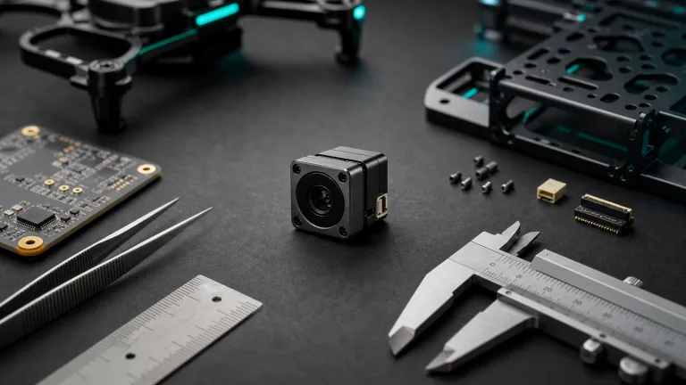
The CAMCUDA FlexMini 640 is an ultra-compact, high-sensitivity thermal core built specifically for SWaP-constrained drone gimbals, tactical pods, and small robotic platforms. Built around a $640 \times 512$ Vanadium Oxide (VOx) array with a tight $12\ \mu\text{m}$ pixel pitch, it delivers thermal sensitivity of $\le 30\text{ mK}$ (NETD @ F1.0, 25°C). Weighing only 23.1 g and drawing less than 0.7 W during full 50 Hz operation, it drops easily into miniature stabilized gimbals.
Comprehensive Technical Specifications:
| Detector Type | Uncooled Vanadium Oxide (VOx) Microbolometer |
|---|---|
| Array Resolution | $640 \times 512\text{ pixels}$ |
| Pixel Pitch | $12\ \mu\text{m}$ |
| Spectral Range | $8\text{ to }14\ \mu\text{m}$ (LWIR) |
| Thermal Sensitivity (NETD) | $\le 30\text{ mK}\ (@ 25^\circ\text{C}, F1.0)$ |
| Output Frame Rate | 50 Hz continuous |
| Module Weight | 23.1 g (chassis baseline) |
| Power Consumption | < 0.7 W nominal operating power |
| Supply Voltage | 5–24 V DC wide-voltage direct input |
| Interface Options | CVBS (PAL/NTSC), USB UVC, MIPI CSI-2 |
| Connector Pinouts | UVC: USB-VDD, D-, D+, GND | CVBS: Rx, Tx, CVBS, GND, VCC |
| Operating Temperature | $-20^\circ\text{C to }+60^\circ\text{C}$ |
| Factory Lens Selection | 4.1mm (Extra-wide), 4.9mm ($76.2^\circ$), 9.1mm ($45.8^\circ$), 13mm ($33.0^\circ$), 19mm ($22.9^\circ$), 35mm ($12.5^\circ$) |
| Sample Unit Pricing | 9.1mm: $423.10 | 4.9mm: $518.31 | 4.1mm: $518.31 | Telephoto lenses: Quoted via RFQ |
CAMCUDA Era-X Long-Range Optical Rangefinder
Visible-Light Full HD CMOS Imaging & Long-Distance Precision Rangefinding Device
The CAMCUDA Era-X Series is a precision electro-optical observation and rangefinding instrument engineered for field survey teams, perimeter surveillance platforms, and multi-sensor payload designs. Pairing a $1920 \times 1080$ full-color CMOS sensor with a 100mm optical telephoto lens, Era-X provides clear visual target documentation alongside an integrated laser rangefinder measuring targets from 50 meters up to 6,000 meters with $\pm2\text{ m}$ accuracy at distances $\le 2000\text{ m}$.
Comprehensive Technical Specifications:
| Sensor Modality | CMOS Full-Color Visible Light (Non-Thermal) |
|---|---|
| Image Resolution | $1920 \times 1080\text{ pixels}$ (Full HD) |
| Optical Focal Length | 100 mm telephoto observation system |
| Rangefinder Scale | 50 m to 6,000 m line-of-sight measurement |
| Range Accuracy | $\pm 2\text{ m}$ at distances $\le 2,000\text{ m}$ |
| Integrated Display | High-contrast OLED contextual eyepiece/display |
| Documentation Capability | High-resolution onboard Photo & Video recording |
| Operating Temperature | $-20^\circ\text{C to }+50^\circ\text{C}$ |
| Storage Temperature | $-45^\circ\text{C to }+60^\circ\text{C}$ |
| Target Workflows | Industrial inspection, search support, boundary survey, perimeter monitoring |
| Compliance Documentation | NDAA statement available on request; export compliance reviewed per RFQ |
7. Aerial Payload Integration Checklist
Before you freeze your mechanical CAD drawings, cut tooling for the enclosure, or spin up the flight line, run through this pre-flight verification checklist:
Pre-Production Payload Engineering Checklist
✅ 1. Mechanical Center of Gravity (CoG) & Inertia:
Verify that the enclosure places total sensor mass right at the intersection of the pitch, yaw, and roll axes. Factor in front-heavy mass shifts when swapping from compact 4.9mm optics to larger 35mm telephoto lenses.
✅ 2. Optical Window Transmission Matching:
Ensure external payload windows use anti-reflective (AR) coated monocrystalline Germanium (Ge), Zinc Selenide (ZnSe), or Chalcogenide glass for LWIR sensors. Standard optical glass, sapphire, or polycarbonate will completely blind an 8–14 µm thermal sensor.
✅ 3. Thermal Dissipation & Conductive Paths:
Confirm that the thermal core’s chassis mount makes clean, direct contact with your aluminum or magnesium housing. Use high-conductivity thermal pads (≥3.0 W/m·K) to prevent hot spots from building up around the ROIC.
✅ 4. Ground Planes & Power Noise Rejection:
Maintain a clean star ground between the thermal core, gimbal controller, and onboard flight computer. Keep sensitive video lines shielded from high-current ESC switching noise and brushless motor leads.
✅ 5. NUC Shutter Mechanical Clearance:
Make sure the internal calibration shutter has plenty of physical clearance inside the pod. Set up your flight software to trigger Non-Uniformity Correction (NUC) via serial commands during loitering rather than during fast manual tracking runs.
✅ 6. High-Speed Line Shielding:
Wrap MIPI CSI-2 and USB differential pairs in braided copper mesh or copper foil tape to keep high-frequency harmonics from degrading the sensitivity of your onboard GPS/GNSS receivers or C2 data links.
8. Deep-Dive Integration FAQ
Why are uncooled LWIR thermal cores preferred over active digital NIR systems for night vision drones?
How does payload power consumption directly affect drone gimbal stability and flight endurance?
What considerations govern thermal lens selection for low-altitude vs. high-altitude drone operations?
Why can standard optical glass not be used as a protective window for thermal drone cameras?
What are the technical advantages of integrating a wide-voltage (5–24 V) input thermal module?
📚 References & Further Reading
- Industry Standard: Sierra-Olympic Technologies – Advanced Infrared Imaging Systems & Optical Cores
- Industry Standard: Autel Robotics – Enterprise Aerial Robotics & Thermal Drone Platforms
- Related Guide: High-Resolution Thermal Imaging Camera OEM Selection Guide
- Related Guide: CVBS Thermal Camera Module Analog Video Integration Guide
- Product Catalog: Explore CAMCUDA OEM Cores, Rangefinders & Electro-Optical Systems
- Engineering RFQ: Request Mechanical CAD Models, SDKs & Direct Technical Review