Drone with Night Vision Camera: Thermal LWIR vs. Low-Light OEM Integration Guide
Drone with Night Vision Camera: Thermal LWIR vs. Low-Light OEM Integration Guide
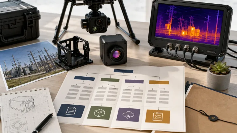
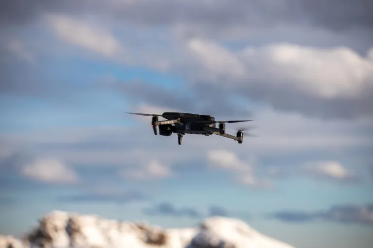
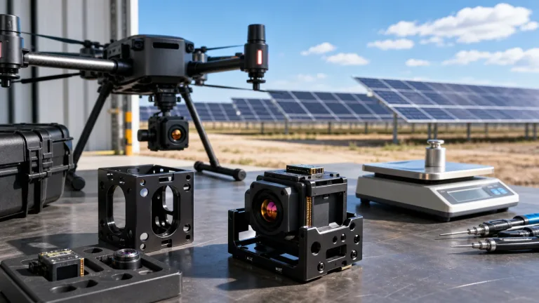
Designing an autonomous or remotely piloted drone with night vision camera capabilities requires navigating fundamental physics trade-offs between visible light amplification, active Near-Infrared (NIR) illumination, and passive Long-Wave Infrared (LWIR) thermography. Unmanned aerial vehicle (UAV) systems operating across defense reconnaissance, perimeter security, critical infrastructure inspection, precision agriculture, and search-and-rescue (SAR) face unpredictable atmospheric conditions, complete zero-lux environments, and unforgiving Size, Weight, Power, and Cost (SWaP-C) constraints. Payload architects must systematically determine whether digital low-light CMOS sensors, uncooled LWIR microbolometers, or fused dual-spectrum AI electro-optical/infrared (EO/IR) gimbals best fulfill target detection, recognition, and identification (DRI) operational mandates.
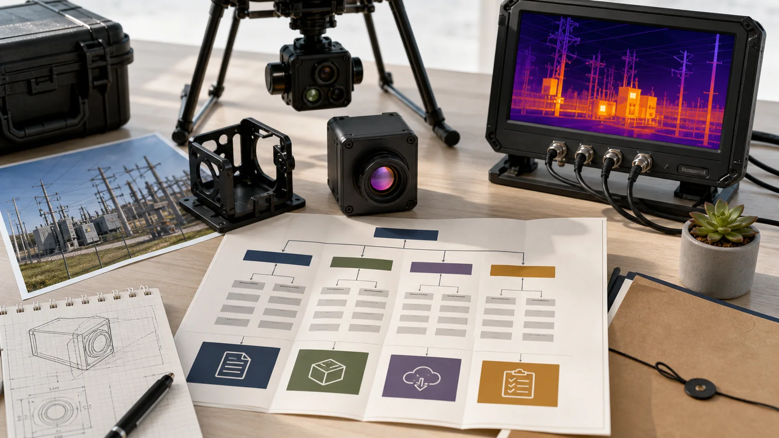
Integrating high-performance night vision imaging hardware onto micro-UAVs, sub-250g tactical platforms, or stabilized multi-axis micro-gimbals introduces complex mechanical, electrical, and optical engineering challenges. Hardware designers must balance pixel pitch scaling (from legacy 12 µm architectures down to next-generation 8 µm nodes), high-speed MIPI CSI-2 and parallel LVCMOS bus routing, transient power supply noise suppression (maintaining ripple under 10 mV peak-to-peak), and edge compute execution for real-time target tracking (from 1 to 6 TOPS). This comprehensive OEM integration guide examines sensor physics, mechanical thermal dissipation, electrical interface pinouts, optical calculations, and sensor fusion pipelines, utilizing production-ready thermal and multi-spectral modules from CAMCUDA to accelerate engineering deployment cycles.
Table of Contents
- 👉 1. Optical Physics: Digital Low-Light CMOS vs. Passive LWIR Thermography
- 👉 2. SWaP-C Payload Engineering & Thermal Dissipation on UAVs
- 👉 3. Dual-Spectrum Sensor Fusion & Edge AI Target Tracking
- 👉 4. Standardized OEM Camera Specifications & Comparison Matrix
- 👉 5. Electrical Interfacing, Clock Synchronization & Video Pipelines
- 👉 6. Optical Calculations: IFOV, Athermalization & Johnson’s Criteria
- 👉 7. Comprehensive Integration FAQ
1. Optical Physics: Digital Low-Light CMOS vs. Passive LWIR Thermography
When selecting a night vision payload for an unmanned aircraft, systems engineers must evaluate the fundamental electromagnetic spectrum bands within which sensors operate: Reflected Ambient Energy (Visible to Near-Infrared: 0.4–1.0 µm) versus Emitted Thermal Radiation (Long-Wave Infrared: 8.0–14.0 µm). Understanding the governing physics of each domain prevents costly misapplications in mission-critical environments.
Here’s the deal: trying to force a visible CMOS sensor to do the job of a thermal core in total blackness is a recipe for field failure. In the shop, we see teams burn months trying to clean up noisy low-lux feeds when what they actually needed was raw thermal emission detection.
Digital Low-Light CMOS Sensors (0.4–1.0 µm)
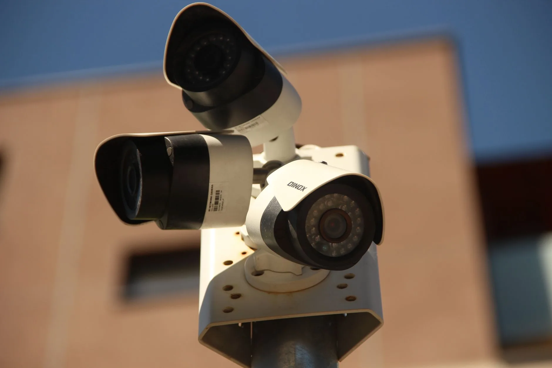
Digital night vision cameras rely on Back-Illuminated (BSI) CMOS focal-plane arrays characterized by large pixel wells, high quantum efficiency (QE) across visible and near-infrared bands, and advanced sub-electron read noise reduction circuitry. As documented in optoelectronic developments published by IEEE Spectrum, high-sensitivity visible sensors (such as 1/2.8-inch and 1/2.6-inch formats with sensitivities ranging from 7341 to 9650 mV/lux·s) can resolve clear, high-definition 1080p imagery in low-light conditions such as civil twilight, full-moon illumination, and ambient urban backscatter (0.01 to 0.1 lux).
Look, CMOS-based night vision systems exhibit inherent physical constraints in tactical and field deployments:
- ⚙️ Total Zero-Lux Failure: In environments devoid of ambient lunar or stellar illumination—such as overcast rural nights, dense canopy forests, subterranean structures, or windowless building interiors—visible CMOS sensors cannot collect photons. The resulting image drops straight into the sensor noise floor.
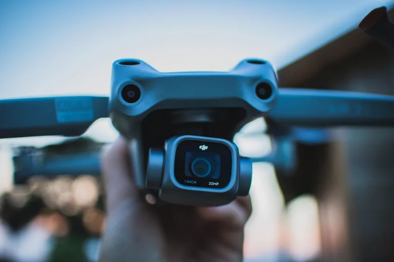
- ⚙️ Active NIR Illuminator Vulnerabilities: To operate in total darkness, visible CMOS systems require supplementary 850 nm or 940 nm Near-Infrared LED spotlights. Active illumination severely degrades SWaP budgets by consuming several watts of DC power, exhibits short effective operational ranges (typically under 20 meters due to inverse-square light falloff), and acts as a bright beacon detectable by opposing night vision devices.
- ⚙️ Atmospheric Scattering: In accordance with Rayleigh and Mie scattering models, shorter wavelengths (0.4–1.0 µm) scatter rapidly when encountering airborne particulate matter. Fog, thick smoke, industrial haze, dust storms, and heavy marine mist completely blind digital CMOS cameras.
Uncooled Long-Wave Infrared Microbolometers (8.0–14.0 µm)
Long-Wave Infrared (LWIR) imaging operates on the physical principle of Planck’s Law and the Stefan-Boltzmann Law, which dictate that all physical matter with a temperature above absolute zero (0 Kelvin / −273.15°C) continuously emits electromagnetic radiation. Uncooled Vanadium Oxide (VOx) focal plane arrays absorb radiant thermal flux across the 8–14 µm atmospheric transmission window. As incident infrared energy heats the microscopic microbolometer bridges, their electrical resistance changes proportionately, allowing read-out integrated circuits (ROICs) to map minute scene temperature variations into high-contrast digital thermal frames.
LWIR microbolometers deliver distinct operational advantages for autonomous drones:
- ✅ True 100% Passive Operation: LWIR cores require absolutely no visible light or artificial illumination. They function identically in bright sunlight, pitch-black moonless nights, and deep underground tunnels.
- ✅ Obscurant and Particulate Penetration: Because the 8–14 µm wavelength is significantly larger than typical atmospheric particulate, smoke, light fog, and haze particles, thermal radiation passes through these obscurants with minimal attenuation, preserving situational awareness where visible optics fail.
- ✅ Thermal Contrast Exploitation: Man-made objects, living targets, running combustion engines, electrical distribution lines, and industrial machinery create distinct thermal contrast against ambient natural backgrounds. This enables automated edge thresholding, target detection, and autonomous tracking regardless of optical camouflage.
For engineering teams designing specialized aerial payloads requiring dedicated thermal cores, CAMCUDA offers an extensive range of precision-manufactured uncooled thermal modules designed for low-latency OEM aerial integration.
2. SWaP-C Payload Engineering & Thermal Dissipation on UAVs
Payload mass, spatial volume, and electrical power consumption directly dictate the flight dynamics, battery discharge rates, operational envelope, and gimbal stability of an unmanned aerial vehicle. System engineers developing a drone with night vision camera capabilities must manage rigorous SWaP-C (Size, Weight, Power, and Cost) trade-offs during initial hardware architecture freezes.
Rotational Inertia and Gimbal Dynamics
Every single gram added to a drone’s nose-mounted or belly-mounted gimbal assembly exponentially increases the rotational inertia ($J = m \cdot r^2$) across the pitch, roll, and yaw axes. Heavier camera modules require higher-torque brushless gimbal motors, stiffer damping grommets, and heavier counterbalances, which in turn increase gross takeoff weight (GTOW) and degrade battery flight endurance. Miniature thermal cores—such as the CAMCUDA SuperMini 640 LWIR core—address this engineering constraint directly. With an ultra-compact 13 × 13 × 13.4 mm footprint and a mass of less than 3.5 g, the core allows direct integration into 20 mm micro-gimbals and sub-250g nano-UAV airframes without degrading aerodynamic stability.
Thermal Management and Sensor Drift Mitigation
Uncooled VOx microbolometers are highly sensitive to thermal conduction and ambient chassis temperature fluctuations. In an enclosed drone payload or sealed multi-sensor pod, heat generated by flight controllers, electronic speed controllers (ESCs), companion AI single-board computers (SBCs), and image signal processors (ISPs) can conduct directly into the sensor substrate, causing non-uniformity drift, fixed pattern noise (FPN), and radiometric measurement errors:
- ⚙️ Low Core Dissipation: The imaging core must maintain an ultra-low power baseline. The SuperMini 640 core operates at $\le 0.5\,\text{W}$ typical power consumption, eliminating the need for bulky active cooling fans or heavy heat pipes within the gimbal pod.
- ⚙️ Structural Heat Sinking: OEM mechanical enclosures should implement isolated structural conduction paths. Precision-machined 6061-T6 aluminum or magnesium alloy mounting flanges should direct heat away from the focal-plane array housing toward exterior chassis surfaces exposed to propeller prop-wash airflow.
- ⚙️ Shutter-Free Scene-Based Calibration: To prevent mechanical shutter actuations from interrupting mission-critical video or tracking lock during flight maneuvers, camera firmware should support scene-based non-uniformity correction (SBNUC) algorithms that dynamically compensate for thermal gradient shifts.
3. Dual-Spectrum Sensor Fusion & Edge AI Target Tracking
While standalone thermal cameras provide superior target detection in complete darkness, they lack high-frequency spatial details such as text, optical color markers, fine wire lines, and structural surface textures. Conversely, visible cameras capture high-resolution details during daylight and twilight but fail in zero-lux or heavy smoke conditions. Modern tactical UAV payloads solve this paradigm through dual-spectrum electro-optical/infrared (EO/IR) sensor fusion coupled with on-module Edge AI processing.
Optical Fusion Architectures
By co-aligning a high-resolution visible sensor (e.g., 1080p CMOS) with an uncooled LWIR microbolometer, the payload processor can execute real-time image fusion using two primary computational pipelines:
- ✅ Pixel-Level Alpha Blending & Edge Extraction: High-pass spatial edge filters (such as Sobel or Laplacian operators) extract crisp geometric outlines from the 1080p visible stream. These edges are dynamically aligned and overlaid onto the $640 \times 512$ thermal false-color palette. The result is an augmented composite stream that preserves both thermal signature contrast and optical structural clarity.
- ✅ Picture-in-Picture (PiP) & Dual Stream Switching: The video pipeline concurrently processes a wide-angle visible feed for broad situational piloting awareness alongside an inset thermal telephoto window for rapid hot-spot verification, enabling the operator to cross-validate targets without switching display modes.
Edge AI Acceleration (1 TOPS vs. 6 TOPS Architectures)
Offloading computer vision workloads from the central drone flight computer onto dedicated camera-integrated Neural Processing Units (NPUs) ensures low-latency closed-loop tracking. The CAMCUDA AI VisionCube series implements scalable edge AI computing directly on the camera stack:
- ⚙️ 1 TOPS Processing Architecture (S, ST, ST Pro): Optimized for lightweight edge inferencing, executing quantized INT8 YOLO models for real-time bounding-box detection of human personnel, vehicles, and maritime vessels at 30 to 50 Hz frame rates.
- ⚙️ 6 TOPS Processing Architecture (D, DT, DT Pro): Delivers advanced computational headroom capable of executing multi-class semantic segmentation, multi-target trajectory prediction, real-time dual-visible optical switching (seamlessly transitioning between 3.9 mm wide-angle and 12 mm telephoto optics), and autonomous target re-identification (ReID) during optical occlusions.
For system integrators seeking implementation details regarding hardware control commands, serial communication protocols, and AI tracking register sets, consult our detailed CAMCUDA support documentation.
4. Standardized OEM Camera Specifications & Comparison Matrix
Below are the comprehensive, unedited engineering specifications and physical characteristics for CAMCUDA’s flagship drone night vision and thermal imaging product families.
CAMCUDA AI VisionCube Visible & Thermal Camera Modules
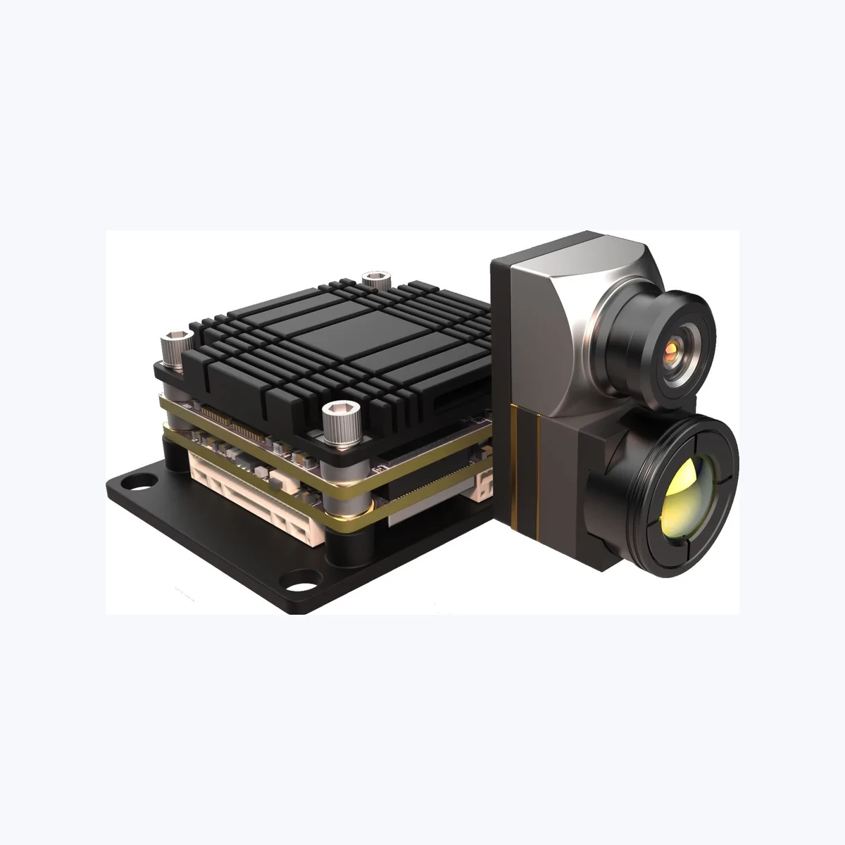
The CAMCUDA AI VisionCube family delivers a unified, modular multi-spectral imaging platform engineered for civilian inspection, industrial observation, and autonomous UAV payloads. Offering six standard factory configurations, the VisionCube series allows designers to pair single or dual visible CMOS optics with 1 TOPS or 6 TOPS on-module AI processing, and seamlessly integrate uncooled LWIR thermal imaging cores up to 640 × 512 resolution at 50 Hz.
Configuration Matrix
| Model | Visible Camera | AI Processing | Thermal Imaging Core |
|---|---|---|---|
| AI VisionCube S | Single Visible (1080p) | 1 TOPS | None |
| AI VisionCube D | Dual Visible (Wide + Tele) | 6 TOPS | None |
| AI VisionCube ST | Single Visible (1080p) | 1 TOPS | 384 × 288 / 25 Hz (12 µm) |
| AI VisionCube DT | Dual Visible (Wide + Tele) | 6 TOPS | 384 × 288 / 25 Hz (12 µm) |
| AI VisionCube ST Pro | Single Visible (1080p) | 1 TOPS | 640 × 512 / 50 Hz (12 µm) |
| AI VisionCube DT Pro | Dual Visible (Wide + Tele) | 6 TOPS | 640 × 512 / 50 Hz (12 µm) |
Visible Optical Specifications
| Specification | S / ST / ST Pro (Single) | D / DT / DT Pro (Dual) |
|---|---|---|
| Visible Resolution | 1920 × 1080 @ 30 Hz | 1920 × 1080 @ 30 Hz |
| Lens Focal Lengths | 4 mm Fixed Focus | 3.9 mm Wide + 12 mm Telephoto |
| Wide / Single FOV | 69° H × 42° V | 72° H × 45° V |
| Telephoto FOV | N/A | 26° H × 15° V |
| CMOS Sensor Format | 1/2.8-inch BSI CMOS | 1/2.8″ Single sub / 1/2.6″ Dual sub |
| Supplied Sensitivity | 7341 mV/lux·s | 9650 mV/lux·s |
| Module Dimensions | 19 × 19 × 30 mm | 40.8 × 25 × 26 mm |
Integrated Thermal Specifications
| Specification | ST / DT (Standard Thermal) | ST Pro / DT Pro (Pro Thermal) |
|---|---|---|
| Thermal Array Resolution | 384 × 288 @ 25 Hz | 640 × 512 @ 50 Hz |
| Pixel Pitch & Spectral Band | 12 µm · 8–14 µm LWIR | 12 µm · 8–14 µm LWIR |
| Thermal Lens & FOV | 9.1 mm (20.3° H × 15.2° V) | 9.1 mm (45.9° H × 36.9° V) |
| Thermal Module Weight | 32.4 g | ≤23 g (excluding lens & connectors) |
| Module Enclosure Dimensions | 26 × 26 × 32.85 mm | 26 × 26 × 21.1 mm (core block) |
CAMCUDA SuperMini 640 / 640T Ultra-Light LWIR Thermal Camera Module
The CAMCUDA SuperMini 640 / 640T sets an industry benchmark for ultra-low SWaP uncooled thermal imaging. Combining an uncooled 640 × 512 VOx microbolometer, an advanced 8 µm pixel pitch node, and an ultra-compact 13 × 13 × 13.4 mm core footprint weighing less than 3.5 g, the SuperMini series is purpose-engineered for micro-UAV gimbals, tactical nano-drones, FPV aerial systems, and compact industrial night-vision payloads.
Model Functional Differentiation
| Functional Parameter | SuperMini 640 (Imaging Core) | SuperMini 640T (Thermographic Core) |
|---|---|---|
| Primary Application | Low-latency night vision & piloting | Radiometric inspection & thermography |
| Frame Rate | 50 Hz (High temporal fluidity) | 30 Hz (Radiometric output) |
| Temperature Measurement | Non-radiometric (Imaging only) | −20°C to +150°C and 100°C to +650°C |
| Digital Video Bus | 8-bit LVCMOS / BT656 and 2-lane MIPI | CDS3 and 2-lane MIPI (Temp stream) |
| Typical Core Power | ≤0.5 W | ≤0.5 W |
| Sensitivity (NETD) | ≤40 mK @ 25°C, F1.0 | ≤40 mK @ 25°C, F1.0 |
Athermal Optical Assembly Configurations (F1.0)
| Focal Length | Field of View (H × V) | Spatial Resolution (IFOV) | Aperture & Thermal Speed |
|---|---|---|---|
| 3.7 mm | 90.0° × 68.2° (Ultra-Wide) | 2.16 mrad | F1.0 Athermalized |
| 6.1 mm | 46.6° × 37.6° (Wide-Field) | 1.31 mrad | F1.0 Athermalized |
| 8.7 mm | 40.0° × 32.2° (Balanced Recon) | 0.92 mrad | F1.0 Athermalized |
| 11.0 mm | 24.9° × 20.0° (Narrow Tele) | 0.73 mrad | F1.0 Athermalized |
5. Electrical Interfacing, Clock Synchronization & Video Pipelines
Successful physical and electrical integration of an LWIR thermal camera module into a drone carrier board requires strict compliance with power filtering specifications, signal line termination, and clock phase alignments. Thermal ROICs are susceptible to high-frequency switching noise common in drone power distribution systems.
Power Rail Decoupling and Ripple Constraints
The CAMCUDA SuperMini 640/640T module utilizes a high-density Hirose DF40C-30DP-0.4V(51) 30-pin board-to-board connector. Carrier boards must supply clean, isolated DC rails adhering to the following parameters:
| Power / Signal Path | Operating Voltage Envelope | Noise Tolerance & Routing Requirement |
|---|---|---|
| MAIN_POWER | 3.8 V to 5.2 V (5.0 V Typical) | 10 mV p-p maximum allowable ripple; route with ferrite bead isolation |
| +3.3 V Logic Rail | 3.28 V to 3.32 V | 10 mV p-p maximum noise; supply via dedicated LDO regulator |
| +1.8 V Analog Rail | 1.78 V to 1.82 V | 1 mV RMS maximum (1 Hz–50 kHz); ultra-low noise LDO required |
| Digital Video Interface | 2-Lane MIPI CSI-2 / 8-bit LVCMOS | MIPI preferred for low EMI; BT656 for direct FPGA capture (mutually exclusive) |
| UART Control Bus | 1.8 V CMOS Logic | TX/RX referenced from core; level shifters required for 3.3V/5V host MCUs |
| Analog CVBS / USB | USB 2.0 / 75Ω Composite CVBS | CVBS pin requires external video-buffer IC; USB via optional TMS6102 board |
High-Speed Video Interface Routing
In the shop, laying out high-density drone avionics without strict RF and high-speed rules is asking for trouble. Keep these physical trace constraints pinned on your layout bench:
- ⚙️ MIPI CSI-2 Differential Routing: Route MIPI clock and data lanes with a tightly controlled $100\,\Omega \pm 10\%$ differential impedance. Maintain intra-pair trace length skew below 0.15 mm to avoid phase alignment errors at high bitrates.
- ⚙️ Ground Return Planes: Ensure continuous, unbroken solid ground planes directly beneath high-speed digital pairs. Avoid routing differential signals across split power planes to eliminate radiated electromagnetic interference (EMI) that can disrupt onboard GPS receivers.
- ⚙️ LVCMOS/BT.656 Parallel Bus Termination: If interfacing via parallel 8-bit LVCMOS, insert $22\,\Omega$ to $33\,\Omega$ series damping resistors at the driver pins to minimize signal ringing and reflections across flexible ribbon cables.
Industry-standard methodologies for routing high-speed camera serialization interfaces in airborne robotics are continuously evaluated in technical resources from Vision Systems Design.
6. Optical Calculations: IFOV, Athermalization & Johnson’s Criteria
Selecting appropriate optical focal lengths and understanding spatial resolution geometry is critical to meeting target Detection, Recognition, and Identification (DRI) operational requirements according to Johnson’s Criteria.
Instantaneous Field of View (IFOV) Calculation
The spatial sampling capability of a thermal camera is governed by its Instantaneous Field of View ($\text{IFOV}$), defined as the angle subtended by a single detector pixel through the optical focal length:
$$\text{IFOV} = \frac{\text{Pixel Pitch } (p)}{\text{Focal Length } (f)}$$
For the CAMCUDA SuperMini 640 core featuring an advanced $8\,\mu\text{m}$ ($0.008\,\text{mm}$) pixel pitch:
- ⚙️ 3.7 mm Optics: $\text{IFOV} = \frac{0.008\,\text{mm}}{3.7\,\text{mm}} = 2.16\,\text{mrad}$ (Offers an ultra-wide $90.0^\circ \times 68.2^\circ$ FOV for close-range obstacle avoidance and wide situational piloting).
- ⚙️ 6.1 mm Optics: $\text{IFOV} = \frac{0.008\,\text{mm}}{6.1\,\text{mm}} = 1.31\,\text{mrad}$ ($46.6^\circ \times 37.6^\circ$ FOV for medium-range perimeter surveillance).
- ⚙️ 8.7 mm Optics: $\text{IFOV} = \frac{0.008\,\text{mm}}{8.7\,\text{mm}} = 0.92\,\text{mrad}$ ($40.0^\circ \times 32.2^\circ$ FOV balancing area coverage with target resolution).
- ⚙️ 11.0 mm Optics: $\text{IFOV} = \frac{0.008\,\text{mm}}{11.0\,\text{mm}} = 0.73\,\text{mrad}$ ($24.9^\circ \times 20.0^\circ$ FOV optimized for standoff target identification).
Johnson’s Criteria Target Range Calculations
Johnson’s Criteria defines the resolving power required across a critical target dimension ($H_c$, typically $1.8\,\text{m}$ for human personnel or $2.3\,\text{m}$ for vehicles):
- ✅ Detection (1.5 cycles / 3 pixels): The probability that an object of interest is present in the scene.
- ✅ Recognition (6.0 cycles / 12 pixels): The ability to classify the target (e.g., distinguishing a person from an animal or a truck from a car).
- ✅ Identification (12.0 cycles / 24 pixels): The ability to discern specific target features (e.g., identifying whether a person is carrying an object).
The maximum operational range ($R$) is calculated via:
$$R = \frac{H_c}{N_{\text{pixels}} \cdot \text{IFOV}}$$
Utilizing the SuperMini 640 equipped with an 11.0 mm lens ($\text{IFOV} = 0.73\,\text{mrad} = 0.00073\,\text{rad}$) against a $1.8\,\text{m}$ human target:
- ✅ Detection Range ($N = 3$): $R_{\text{det}} = \frac{1.8}{3 \cdot 0.00073} \approx 821\,\text{meters}$
- ✅ Recognition Range ($N = 12$): $R_{\text{rec}} = \frac{1.8}{12 \cdot 0.00073} \approx 205\,\text{meters}$
- ✅ Identification Range ($N = 24$): $R_{\text{id}} = \frac{1.8}{24 \cdot 0.00073} \approx 102\,\text{meters}$
Athermal Optical Design in UAV Operating Environments
Drones experience rapid thermal shifts during flight, transitioning from ambient ground temperatures ($+35^\circ\text{C}$) to high-altitude cold environments ($-15^\circ\text{C}$). Standard optical materials expand and contract with temperature changes, shifting the focal plane away from the sensor surface. CAMCUDA optical assemblies employ F1.0 athermalized mechanical barrels, which combine specialized optical materials with mechanical compensation housings that passively offset thermal expansion, maintaining sharp optical focus across the entire operating temperature envelope without requiring active motor focusing.
7. Comprehensive Integration FAQ
What is the practical engineering difference between a digital low-light CMOS night vision camera and an uncooled LWIR thermal camera on drones?
Uncooled Long-Wave Infrared (LWIR) microbolometers operate in the 8.0–14.0 µm thermal emission spectrum, detecting the passive heat emitted by all physical objects above absolute zero. LWIR thermal cameras operate completely independently of visible light, functioning identically in total darkness and bright sunlight while penetrating smoke, dust, and light foliage. For 24/7 all-weather drone operations, tactical security, and industrial inspection, LWIR thermal or dual-spectrum (EO/IR) fused payloads provide reliable target detection and tracking where digital CMOS sensors cannot function.
Why do low-cost consumer night vision drone setups suffer from short detection ranges and poor tracking reliability?
First, the small pixel dimensions and high read noise of consumer CMOS sensors result in a low signal-to-noise ratio (SNR) in low-light environments. Under low-lux conditions, automatic gain control circuits introduce severe temporal noise and motion blur, which disrupts onboard computer vision and tracking algorithms during flight maneuvers. Second, the integrated consumer IR LEDs emit highly divergent light with low optical power (typically 1–3 Watts), limiting effective illumination to short distances of 5 to 15 meters due to inverse-square optical falloff. Third, consumer systems lack long-wave infrared microbolometer arrays and athermal Germanium optics capable of long-range thermal detection.
Industrial and defense drone platforms overcome these limitations by utilizing uncooled 640 × 512 VOx microbolometers with small pixel pitches (such as 8 µm or 12 µm) paired with F1.0 athermalized telephoto optics. This enables passive human target detection at ranges exceeding 800 meters and vehicle detection beyond 1.5 kilometers in complete darkness.
📚 References & Further Reading
- Industry Standard: IEEE Spectrum
- Industry Standard: Vision Systems Design
- Related Guide: CAMCUDA Uncooled Thermal Imaging Modules
- Related Guide: CAMCUDA SuperMini 640 / 640T Ultra-Light LWIR Core
- Related Guide: CAMCUDA Technical Integration Support & FAQ