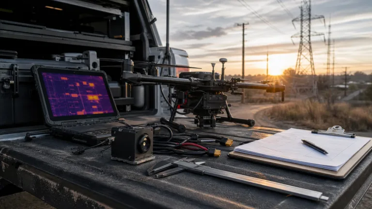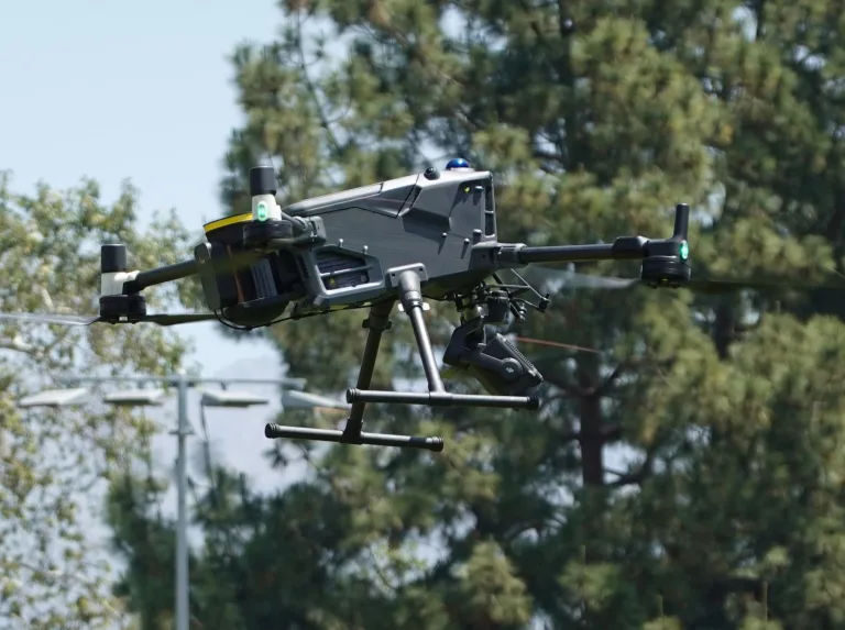
How to Select & Integrate a UAV with Infrared Camera: OEM Engineering Guide
How to Select & Integrate a UAV with Infrared Camera: OEM Engineering Guide
Integrating an uncooled thermal imaging payload into an unmanned aerial vehicle (UAV) is no longer just about slapping an analog sensor onto a balanced 3-axis gimbal and calling it a day. Modern autonomous and semi-autonomous airborne platforms demand tight, low-latency architectures that pack long-wave infrared (LWIR) detectors, electro-optical (EO) visible sensors, and onboard edge artificial intelligence (AI) processing into brutal Size, Weight, Power, and Cost (SWaP-C) envelopes. For drone OEMs, robotics integrators, and defense subcontractors, the real fight happens at the intersection of optical physics, electrical noise isolation, flight control protocols like CRSF or MAVLink, and multi-spectral computer vision pipelines running in real time.
Here’s the deal: picking the right uav with infrared camera setup comes down to a hard-nosed evaluation of microbolometer detector pitch, thermal sensitivity (NETD), optical focal lengths, and hardware interface bottlenecks. A poorly integrated sensor stack will choke your onboard processing pipelines, dump nasty electromagnetic interference (EMI) straight into your flight controller, or lose target lock the second your airframe cuts through dynamic smoke, low-light chop, or heavy thermal clutter. This engineering guide cuts through the marketing fluff to break down the technical parameters, flight-stack interfacing methodologies, dual-spectrum fusion strategies, and OEM hardware options you need to build mission-ready UAV platforms.
Table of Contents
- 👉 1. Core Physics & Sensor Architectures for UAV Infrared Payloads
- 👉 2. Dual-Spectrum Fusion, Optics & Edge Compute Architectures
- 👉 3. Electrical, Mechanical & Flight Protocol Interfacing (ArduPilot / BetaFlight)
- 👉 4. Deep-Dive OEM Hardware Showcase: Edge AI Thermal Modules
- 👉 5. Technical Comparison Matrix: AI Thermal & Visible Tracking Cores
- 👉 6. Step-by-Step OEM Integration & Ground Testing Workflow
- 👉 7. Mission Profiles, Tactical Deployment & Field Use Cases
- 👉 8. Comprehensive Technical FAQ
- 👉 9. OEM RFQ Checklist & Procurement Specifications
1. Core Physics & Sensor Architectures for UAV Infrared Payloads
Infrared payloads for unmanned systems operate across two primary atmospheric transmission windows: Long-Wave Infrared (LWIR, spanning 8 to 14 μm) and Mid-Wave Infrared (MWIR, spanning 3 to 5 μm). In the sub-25 kg Maximum Takeoff Weight (MTOW) tactical and industrial tier, uncooled Vanadium Oxide (VOx) and Amorphous Silicon (α-Si) microbolometer focal plane arrays (FPAs) dominate the landscape. Why? Because cryo-cooled MWIR Stirling cycle pumps bring immense mass, high power draw, and strict maintenance cycle penalties that just do not fit practical commercial or tactical UAV mission profiles.
Uncooled microbolometer arrays function by absorbing incident infrared radiation on microscopic suspended bridges, changing the material’s electrical resistance. That tiny resistance swing is digitized by a Read-Out Integrated Circuit (ROIC) bonded right beneath the detector array. The overall signal fidelity you get on the bench or in the air is dictated by the thin-film chemistry, pixel geometry, and optical transmission efficiency of the front element.
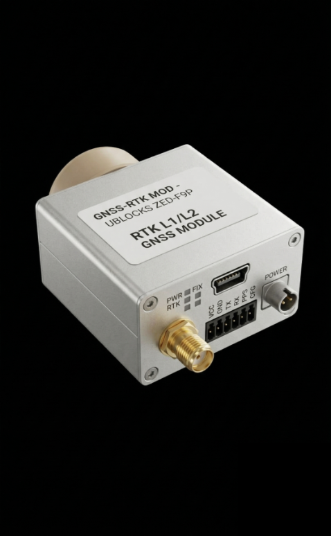
Microbolometer Detector Material: VOx vs. α-Si
Look, when you are speccing a thermal imaging core for aerial target acquisition, your choice of microbolometer material sets your baseline signal-to-noise floor:
- ⚙️ Vanadium Oxide (VOx): VOx remains the benchmark for high-performance airborne imaging cores. It delivers a superior Temperature Coefficient of Resistance (TCR) and substantially lower 1/f flicker noise. This translates to raw Noise Equivalent Temperature Differences (NETD) routinely pushing below 40 mK (and under 30 mK in controlled lab settings). In the field, VOx detectors maintain clean contrast gradients across low-thermal-delta environments like open water search-and-rescue, overcast night tracking, and washed-out terrain surveillance.
- ⚙️ Amorphous Silicon (α-Si): While α-Si arrays benefit from established standard CMOS semiconductor fab lines and slightly lower unit costs, they suffer from elevated 1/f noise floors and lower baseline thermal sensitivity (typical NETD sits between 50 mK and 70 mK). To get usable spatial detail out of an α-Si core at long stand-off distances, optical engineers are forced to run wide-aperture lenses (lower F-number), which immediately stacks unwanted Germanium mass right onto your pan/tilt gimbal.
Pixel Pitch, Optical Apertures, and Ground Sample Distance (GSD)
In the shop, we have watched the industry transition from legacy 17 μm pixel architectures down to modern 12 μm micro-detectors, engineered by tier-one sensor foundries like Teledyne DALSA Infrared Detectors. Shrinking pixel pitch down to 12 μm reduces the physical footprint of the focal plane array for any given resolution (e.g., 640 × 512). This allows lens designers to run smaller, lighter Germanium or Chalcogenide glass elements while preserving the exact same angular field of view, drastically reducing gimbal rotational inertia and motor power consumption.
To calculate whether your camera payload can actually resolve targets at your operational ceiling, use the Instantaneous Field of View (IFOV) relationship:
IFOV (mrad) = [ Pixel Pitch (p in μm) / Focal Length (f in mm) ]
Take a 12 μm (0.012 mm) detector matched with a 9.1 mm thermal lens: this gives an IFOV of roughly 1.318 milliradians. If you fly an inspection profile at 100 meters Above Ground Level (AGL), your Ground Sample Distance (GSD) works out to approximately 13.2 cm per pixel. Under classic Johnson Criteria rules for thermal target acquisition, you need a minimum of 6 to 8 contiguous pixels across a human or vehicle silhouette to achieve positive AI classification. If your GSD is too coarse, your onboard convolutional neural networks will throw false positives all day long.
Thermal Optics: Germanium vs. Chalcogenide Glass
Standard optical crown glass is totally opaque to LWIR photons between 8 and 14 μm. Airborne thermal payloads rely on specialized transmissive substrates:
- ⚙️ Monocrystalline Germanium (Ge): Germanium boasts an exceptionally high refractive index (near 4.0), which lets engineers design compact, low-profile multi-element lenses with tight spherical aberration control. The catch? Germanium is heavy, expensive, and susceptible to thermal defocusing and transmission drop-off (thermal runaway) once internal element temperatures push past 60°C.
- ⚙️ Chalcogenide Glass Alloys: Chalcogenide compounds (like GASIR) provide a lower-density glass option that can be precision molded into complex aspheric profiles. More importantly, Chalcogenide optics exhibit superior passive athermalization behavior across broad operational swings (-20°C to +60°C), preventing the focus plane from drifting when an airframe climbs rapidly through freezing flight levels.
2. Dual-Spectrum Fusion, Optics & Edge Compute Architectures
Standalone thermal imaging is great for spotting hot targets in pitch-black environments or cutting through light dust, but it strips away color signatures, surface textures, and fine text. Dual-spectrum systems solve this by slaving a high-resolution Electro-Optical (EO) visible CMOS sensor alongside an LWIR thermal microbolometer onto a synchronized compute engine.
Image Fusion Modes and Picture-in-Picture (PIP)
Aligning visible and thermal video streams on a fast-moving drone platform without sickening parallax or temporal lag requires tight algorithmic co-registration. Real-world dual-spectrum UAV processors handle this through three main operational pipelines:
- ✅ Picture-in-Picture (PIP) Dynamic Inset: The primary wide-angle visible feed hosts an adjustable inset window showing the thermal channel (or vice-versa). This allows an operator or flight computer to monitor broad situational context while locking target heat signatures right at the reticle center.
- ✅ Dynamic Edge Blending (Alpha Fusion): High-pass spatial edge-detection operators (such as Sobel or Laplacian kernels) pull high-frequency structural boundaries from the 1080p visible stream and superimpose them directly onto the false-color 640 × 512 thermal frame. You get sharp structural definitions—like vehicle door seams, window frames, fence lines, and road paint—rendered right on top of thermal gradients.
- ✅ Thermal Saliency Highlighting: The onboard AI engine runs background thresholding on the thermal feed. When a target exceeds a designated temperature threshold or neural classification confidence, the system renders high-visibility tracking bounding boxes straight onto the HD visible feed.
Edge AI Inference vs. Ground Station Offloading
The old-school way of doing UAV video analytics was piping compressed video down an RF link (COFDM, Wi-Fi, or proprietary digital datalinks) to a ground station laptop running object detection software. In real-world tactical environments, that architecture falls apart fast: link latency spikes to 200–400 ms, video compression artifacts trash edge gradients, and the first hint of RF jamming or multipath fading immediately drops your target lock.
Modern architectures execute neural inference right at the payload edge. Embedded Neural Processing Units (NPUs) delivering 4 to 6 TOPS ingest uncompressed, zero-latency MIPI-CSI2 video straight from the sensor ROIC. By running frame-by-frame inference onboard, processing latency drops as low as 8 ms. The module tracks spatial bounding boxes, velocity vectors, and target centroids locally, feeding compact serial coordinate telemetry directly into autopilots running open-source stacks managed through QGroundControl.
3. Electrical, Mechanical & Flight Protocol Interfacing (ArduPilot / BetaFlight)
In the shop, payload integration headaches almost always trace back to three culprits: dirty power rails, high-frequency frame vibration, and noisy serial communication lines. High-output Electronic Speed Controllers (ESCs) and multi-watt digital video transmitters (VTX) create harsh electrical environments that will wreck microbolometer readout stability if you cut corners on isolation.
Flight Controller Telemetry & Protocol Interfacing
Modern airborne AI tracking modules interface directly with flight controller hardware running ArduPilot, PX4, BetaFlight, or INAV via dedicated UART serial buses:
- ⚙️ CRSF (Crossfire Protocol): The go-to standard for agile multirotors, tactical interceptors, and high-speed FPV-derived platforms. CRSF runs bidirectional serial communication over standard logic-level UARTs at 416,666 baud. The AI camera core decodes pilot switch commands (reticle lock, tracking mode toggle, optical stream switching) and writes real-time target track status and bounding-box coordinates directly into the flight controller’s OSD telemetry stream.
- ⚙️ MAVLink Protocol: The enterprise workhorse for fixed-wing, mapping, and heavy-lift multicopters. The tracking payload generates
TARGET_ABSOLUTEorVISION_POSITION_ESTIMATEMAVLink packets, allowing the autopilot to execute fully autonomous closed-loop flight maneuvers such as automated target orbiting, lead-angle pursuit, and guided visual approaches.
Electrical Power Filtering and Grounding Rules
Microbolometers and high-speed NPUs demand ultra-clean DC power. If your power rail fluctuates under heavy motor throttle punches, your thermal image will crawl with horizontal banding noise and sensor calibration will drift. Follow these bench-tested rules:
- ⚙️ Dedicated DC-DC Step-Down Regulation: Never run an AI thermal core directly off raw propulsion LiPo battery leads. Implement an isolated, filtered step-down switching regulator supplying a tightly controlled 9V to 16V DC rail with output ripple clamped below 50 mV peak-to-peak under full load.
- ⚙️ TVS Transient Suppression: Active regenerative motor braking (damping light) kicks massive inductive voltage spikes back into the main DC bus. Solder a high-joule Transient Voltage Suppression (TVS) diode paired with low-ESR solid electrolytic capacitors at the payload power entry point to clamp dangerous voltage transients.
- ⚙️ Star Grounding Architecture: Tie the AI payload, flight controller, and video transmitter grounds together at a single common star-ground reference. Ground loops between video signals and flight controllers create 50/60 Hz rolling hum bars on analog feeds and induce clock jitter across high-speed digital lines.
Mechanical Damping & Thermal Dissipation
Motor imbalances and propeller wash generate high-frequency structural harmonics (typically centered between 100 Hz and 400 Hz) that can induce microphonic resonance on delicate microbolometer membrane structures. Isolate camera payload mounts using silicone or fluoro-silicone dampers rated between 40 and 50 Shore A durometer. On the thermal management side, a 6 TOPS onboard processor churning through multi-target tracking generates real heat. Make sure your payload housing or airframe pod directs forced prop-wash airflow across the aluminum heatsink casing to prevent thermal throttling during extended hover profiles.
4. Deep-Dive OEM Hardware Showcase: Edge AI Thermal Modules
For system integrators building custom dual-spectrum or visible-tracking UAV airframes, these turnkey edge-compute camera payloads offer drop-in reliability and verified flight-stack compatibility.
TM02-SOLO T: 6 TOPS UAV AI Tracking Module with 640 Thermal Camera
The TM02-SOLO T is an integrated dual-spectrum edge-AI tracking platform built specifically for drone OEMs, tactical airframes, and robotics integrators. It merges a 1080p visible CMOS sensor running at 120 Hz with an uncooled 640 × 512 VOx long-wave infrared camera, orchestrated by a dedicated 6 TOPS edge compute engine.
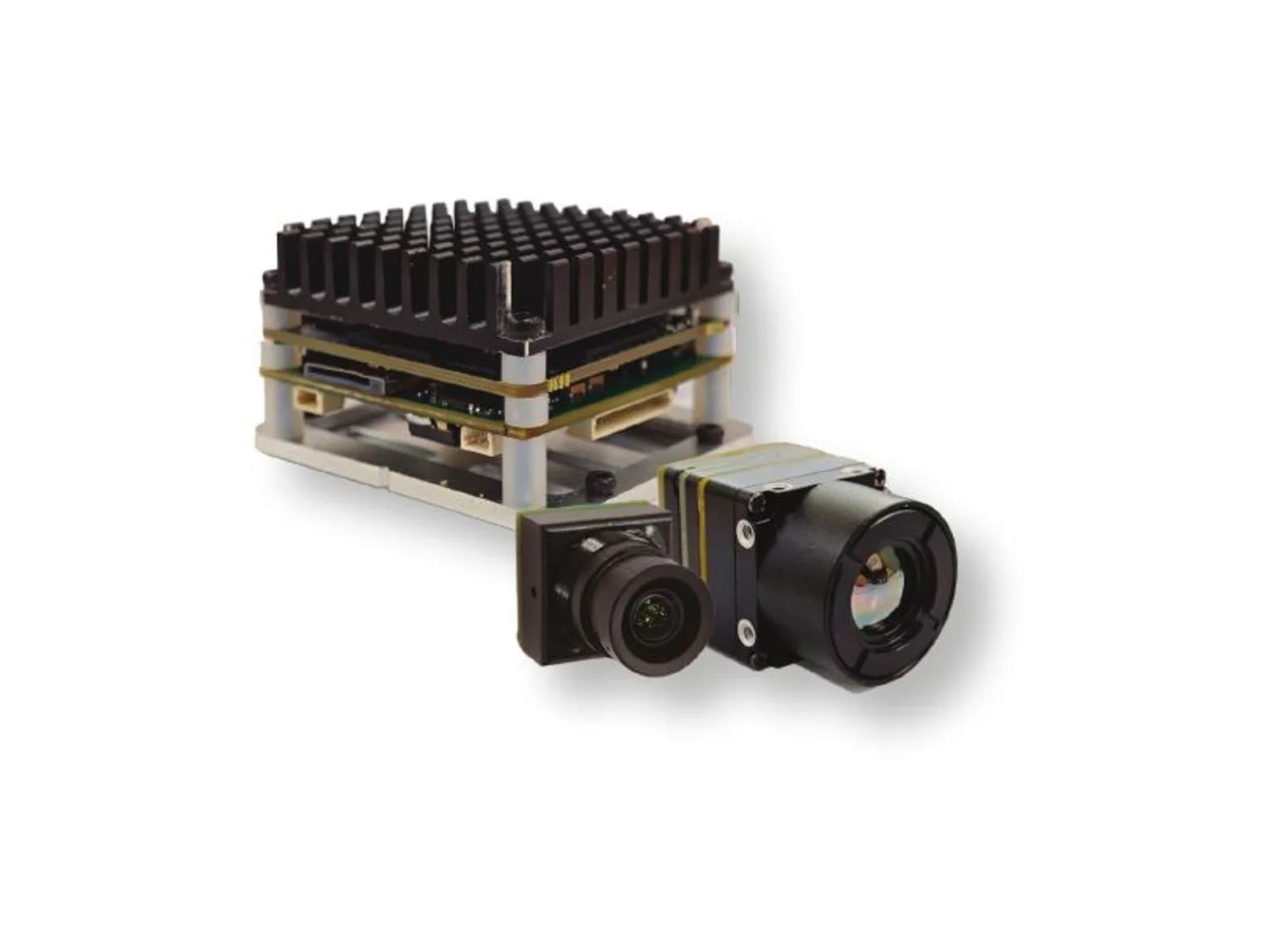
Engineered for mission envelopes spanning full daylight, degraded visual environments, zero-lux night operations, and low-contrast thermal backgrounds, the TM02-SOLO T handles all computer vision heavy lifting on the aircraft. Its 6 TOPS heterogeneous processor (featuring quad-core Arm Cortex-A76 at 2.4 GHz and Cortex-A55 at 1.8 GHz) tracks up to 120 target tracks concurrently. Tracking features include reticle locking, close-to-lock, route pre-mapping, and lost-target re-acquisition at target relative speeds up to 450 km/h.
| TM02-SOLO T Technical Parameters | |
|---|---|
| AI Compute & CPU | 6 TOPS NPU | Arm Cortex-A76 (2.4 GHz) + Cortex-A55 (1.8 GHz) |
| Thermal Detector | Uncooled VOx microbolometer, 8–14 μm spectral band |
| Thermal Resolution & Rate | 640 × 512 @ 50 Hz (12 μm pixel pitch) |
| Thermal Optics & FOV | 9.1 mm focal length | D 61.8° / H 47.7° / V 38.2° |
| Visible (EO) Camera | 1/1.8″ CMOS, 1920 × 1080 @ 120 Hz (0.001 lux min. illumination) |
| Visible Optics & FOV | 8.45 mm focal length | D 66.3° / H 57.1° / V 30.4° |
| Target Range Reference | Vehicle: 400 m | Person: 170 m (supplier reference) |
| Min. Target Size & Latency | 10 × 10 pixels | 8 ms supplier table processing latency reference |
| Flight Protocol & Voltage | CRSF Protocol (BetaFlight & ArduPilot) | Regulated 9–16V DC |
| Dimensions & Mount | Board: 45 × 45 × 26 mm | 42.5 × 42.5 mm mounting pattern |
View Product Details & Pricing ➔
TC01-HD: Compact 4 TOPS UAV AI Tracking Module with HD Camera
The TC01-HD is an ultra-compact visual tracking module engineered for micro-drones, lightweight pan/tilt assemblies, and robotics platforms where stack space and weight are tight.
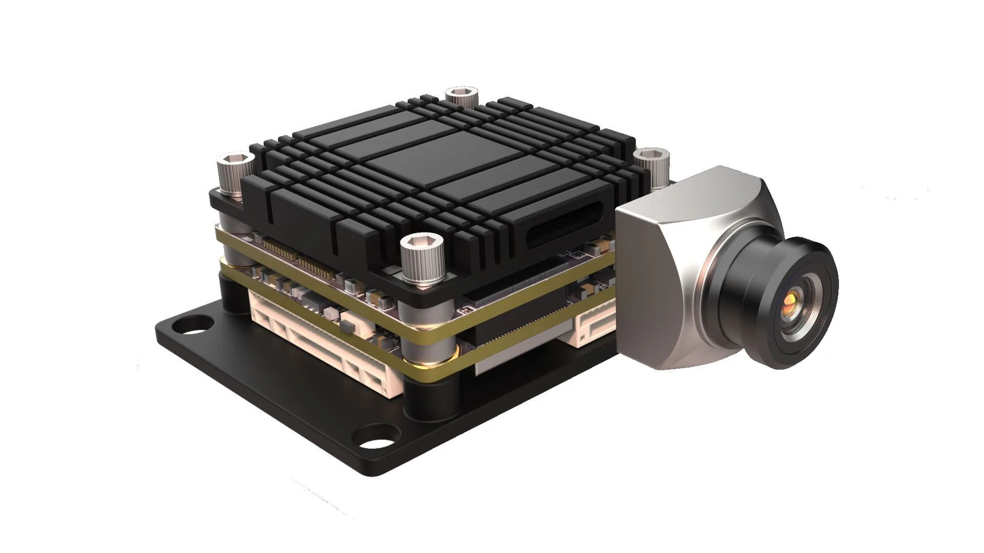
Housed on a 38 × 38 mm board footprint with a standard 25.5 mm mounting pattern, the TC01-HD pairs a 4 TOPS embedded NPU with a 1/1.8-inch CMOS sensor outputting 2160 × 1440 resolution at 60 Hz. The module handles onboard human and vehicle classification, multi-target tracking up to 60 targets, PIP display feeds, and direct CRSF flight controller integration.
| TC01-HD Technical Parameters | |
|---|---|
| AI Compute | 4 TOPS embedded NPU |
| Camera Sensor | 1/1.8″ CMOS (0.001 lux min. illumination reference) |
| Resolution & Frame Rate | 2160 × 1440 @ 60 Hz |
| Optics & FOV | 4.37 mm focal length | D 131.6° / H 109° / V 57.5° (Wide-Angle) |
| Detection Distance Ref. | Vehicle: 800 m | Person: 300 m (supplier optical reference) |
| Processing Latency | 30 ms latency reference |
| Dynamic Speed Ref. | Up to 140 km/h |
| Max Targets & Display | Up to 60 identified targets | PIP display supported |
| Flight Protocol & Voltage | CRSF Protocol (BetaFlight & ArduPilot) | Regulated 9–16V DC |
| Stack Dimensions & Mount | 38 × 38 × 24.5 mm | 25.5 × 25.5 mm mounting pattern |
View Product Details & Pricing ➔
5. Technical Comparison Matrix: AI Thermal & Visible Tracking Cores
When selecting payload electronics, engineering teams have to balance compute throughput, optical spectrum requirements, board size, and protocol integration. For expanded RFQ preparation, review our detailed thermal camera suppliers OEM RFQ checklist.
The comparison matrix below breaks down operational tradeoffs between dual-spectrum tracking units, HD visible tracking engines, and miniature micro-cores such as the TC160-NF 160×120 LWIR thermal imaging module.
| Parameter | TM02-SOLO T Dual-Spectrum | TC01-HD Visible Tracking | TC160-NF Thermal Micro-Core |
|---|---|---|---|
| Imaging Spectrum | Dual: EO Visible + LWIR Thermal | Single: Visible (Wide-Angle EO) | Single: LWIR Thermal (8–14 μm) |
| Thermal Sensor | 640 × 512 VOx (12 μm, 50 Hz) | N/A | 160 × 120 VOx (12 μm) |
| Visible Sensor | 1080p @ 120 Hz (1/1.8″ CMOS) | 1440p @ 60 Hz (1/1.8″ CMOS) | N/A |
| Edge AI Compute | 6 TOPS NPU (A76+A55 CPU) | 4 TOPS Embedded NPU | Direct Stream / External DSP |
| Max Targets | Up to 120 simultaneous tracks | Up to 60 identified targets | Host Controller Dependent |
| Latency Ref. | 8 ms processing latency ref. | 30 ms latency ref. | Sub-frame analog latency |
| Max Target Speed | Up to 450 km/h | Up to 140 km/h | Airframe Speed Dependent |
| Board Dimensions | 45 × 45 × 26 mm (42.5 mm mount) | 38 × 38 × 24.5 mm (25.5 mm mount) | Ultra-miniature core format |
| Flight Stack | BetaFlight, ArduPilot (CRSF) | BetaFlight, ArduPilot (CRSF) | Analog / Serial Telemetry |
| Recommended Input | Regulated 9–16V DC | Regulated 9–16V DC | Regulated 3.3–5.0V DC |
6. Step-by-Step OEM Integration & Ground Testing Workflow
Executing a disciplined hardware integration workflow saves weeks of bench troubleshooting and prevents smoky flight-line failures. Follow this five-phase engineering checklist:
Phase 1: Mechanical Isolation and Thermal Engineering
Machine or 3D-print your mounting bracket from CNC 6061-T6 aluminum or continuous carbon-fiber reinforced nylon. Fasten the module using M2 or M3 hardware dampened with 45-durometer silicone isolation rings to filter motor vibrations between 150 Hz and 350 Hz. Ensure the module heatsink sits in the direct path of rotor downwash during both hover and high-speed forward flight transitions.
Phase 2: Harness Routing and Power Rail Scope Verification
Build a twisted, shielded wiring harness that keeps high-speed MIPI, HDMI, and serial lines physically isolated from high-amperage ESC battery trunks. On the test bench, power the system through a laboratory DC power supply and run full-throttle motor step tests on a thrust stand. Hook an oscilloscope to the 9–16V payload rail to confirm switching noise and motor back-EMF ripple stay strictly below 50 mV peak-to-peak under rapid acceleration and braking transients.
Phase 3: Autopilot Configuration and Serial Protocol Binding
Route the tracking module’s serial TX/RX lines to an open hardware UART on your flight controller (such as UART3 on an ArduPilot H7 or BetaFlight F722 stack). Configure the port for CRSF telemetry at 416,666 baud. In your radio configurator, map auxiliary transmitter switches to payload control modes: configure a 3-position toggle for Tracking Off / Reticle Lock / Multi-Target Auto-Track, and a secondary switch for Visible / Thermal / Dynamic PIP display routing.
Phase 4: Optical Parallax Boresighting
Because the visible sensor lens (8.45 mm) and thermal sensor lens (9.1 mm) sit a few centimeters apart on dual-spectrum modules, physical parallax occurs at close range. Set up a high-contrast heated crosshair calibration target at an exact 50-meter stand-off distance. Use the module’s calibration utility to tune digital X/Y alignment offsets until the visible reticle crosshairs and thermal tracking markers lock in perfect convergence.
Phase 5: Dynamic Ground Tracking & Flight Envelope Verification
Run thorough ground track-retention tests before putting props in the air. Drive test vehicles and walk personnel across the field of view at varying angular velocities to verify bounding-box retention and edge confidence. Test the module’s lost-target recall algorithm by having targets walk behind trees or vehicles. Once ground tests pass, execute flight envelope stress tests—pushing maximum pitch and roll angular rates to ensure high-G maneuvers don’t induce optical desync or serial communication dropouts.
7. Mission Profiles, Tactical Deployment & Field Use Cases
A UAV built with onboard dual-spectrum AI vision gives field operators a massive edge across critical mission profiles:
Tactical ISR and Perimeter Interception
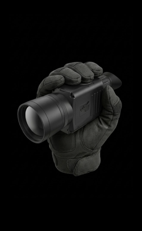
In border defense and perimeter security operations, intruders routinely exploit darkness, dense ground clutter, or camouflage to beat visible cameras. A dual-spectrum drone patrolling at 100 meters AGL uses its 640 × 512 LWIR core to spot human thermal signatures at 170 meters and vehicle heat signatures at 400 meters. Once the edge AI engine acquires the target, it tracks rapid movements up to 450 km/h, streaming real-time coordinate vectors directly back to ground teams. Operators equipped with handheld multi-spectral devices, such as the URA-Z Series dual-light fusion handheld thermal observer, can seamlessly cross-verify aerial coordinates with ground perspectives for coordinated interdiction.
Solar Utility Farms & Power Grid Auditing
Commercial photovoltaic (PV) utility installations cover hundreds of acres where cracked cells, failed bypass diodes, and sub-string shorts produce destructive localized hotspots. Flying a dual-spectrum drone lets the pilot use the 1080p visible channel for safe obstacle clearance and panel labeling while using the thermal core to flag thermal anomalies across strings. Edge AI auto-tracking keeps panels centered in the frame automatically, slashing inspection flight durations by more than 60% compared to manual piloting.
Wilderness Search and Rescue (SAR)
In mountain and wilderness search operations, human thermal signatures can easily get washed out by sun-baked rock faces or dense tree cover. The dual-spectrum processing core runs dynamic edge fusion, overlaying sharp terrain contours and trail pathways from the visible channel directly onto the thermal image layer. The moment a human heat signature pops into a clearing, the AI tracking engine engages its close-to-lock tracking mode, keeping the search target pinned at frame center regardless of aircraft yaw or turbulence.
8. Comprehensive Technical FAQ
What thermal resolution is required for an enterprise UAV infrared inspection payload?
Does an AI thermal imaging UAV payload provide calibrated radiometric temperature measurements?
How do ambient operating temperatures affect uncooled microbolometer tracking performance?
9. OEM RFQ Checklist & Procurement Specifications
To speed up engineering turnaround and avoid costly scope misalignment during quotation reviews, make sure your engineering team specifies these core parameters before submitting a Request for Quotation (RFQ):
1. Target Platform & Flight Stack Architecture
- ⚙️ Airframe Category: Multirotor, fixed-wing pusher/puller, tactical VTOL, or ground robotic platform.
- ⚙️ Flight Controller & Firmware: ArduPilot (firmware release), BetaFlight (target/release), PX4, or proprietary autopilot hardware.
- ⚙️ Telemetry Bus: CRSF serial UART, MAVLink serial, S.Bus, or Ethernet/IP telemetry.
2. Optical and Thermal Sensor Requirements
- ⚙️ Spectral Channel: Dual-spectrum (EO + LWIR) or single-channel thermal/visible.
- ⚙️ Thermal Resolution: 640 × 512 (e.g., TM02-SOLO T) vs. 160 × 120 (e.g., TC160-NF) vs. specialized sensor formats.
- ⚙️ Optical Field of View (FOV): Narrow/telephoto stand-off optics vs. wide-angle scene coverage (e.g., TC01-HD 109° HFOV).
- ⚙️ Radiometric Requirement: Relative contrast tracking vs. factory-calibrated absolute radiometric temperature output.
3. Onboard Processing & Telemetry Interfaces
- ⚙️ NPU Compute Power: 4 TOPS vs. 6 TOPS onboard edge AI inference.
- ⚙️ Target Classification Classes: Human, vehicle, vessel, or custom customer-trained neural network weights.
- ⚙️ Video Interface: Raw MIPI-CSI2, micro-HDMI, analog CVBS (NTSC/PAL), or compressed H.264/H.265 RTSP over IP.
4. Electrical, Mechanical & Delivery Scope
- ⚙️ Voltage Input Constraints: Regulated 9–16V DC bus vs. custom regulated rail.
- ⚙️ Mechanical Envelope: Maximum mounting pattern (42.5 mm vs. 25.5 mm) and gimbal payload weight ceiling.
- ⚙️ Procurement Scope: Bare board-level stack, integrated sensor/lens assemblies, custom wiring harnesses, or sealed ruggedized modules.
📚 References & Further Reading
- Industry Standard: Teledyne DALSA Infrared Detectors
- Flight Control Architecture: QGroundControl Ground Control Station
- Related Procurement Guide: Thermal Camera Suppliers OEM RFQ Checklist
- Related Component Guide: TC160-NF 160×120 LWIR Thermal Imaging Module
- Tactical Hardware Reference: URA-Z Series Dual-Light Fusion Handheld Thermal Observer