DJI with Thermal Camera: OEM Integration Guide vs Enterprise Drones
DJI with Thermal Camera: OEM Integration Guide vs Enterprise Turnkey Drones
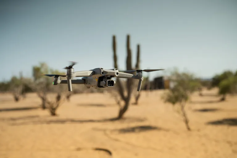
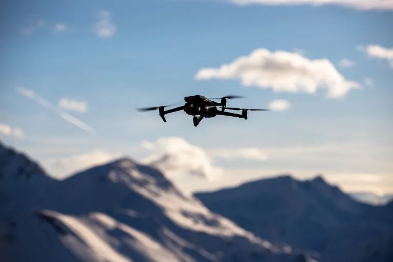
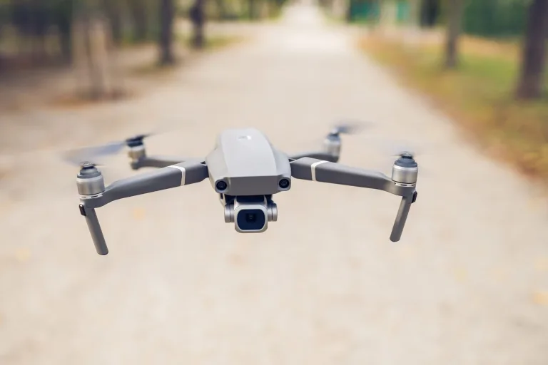
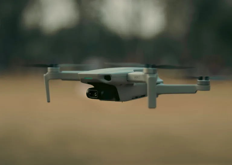
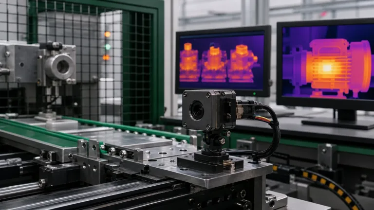
The global demand for DJI with thermal camera systems has exploded across industrial inspection, public safety search and rescue (SAR), tactical reconnaissance, structural health monitoring, and precision agriculture. Commercial off-the-shelf (COTS) turnkey platforms—specifically the DJI Mavic 3 Enterprise Thermal (M3T), the DJI Matrice 30T (M30T), and the Matrice 350 RTK fitted with Zenmuse H20T or H30T optical payloads—have set a solid baseline for getting eyes in the sky fast. These integrated solutions combine visible optical sensors and Long-Wave Infrared (LWIR) microbolometers in a factory-calibrated package, with laser rangefinding on selected models and support through DJI Pilot 2.
Embedded systems engineers, aerospace payload architects, and specialized robotics OEMs need to compare the interfaces and development access available on each turnkey platform. Fixed optical fields of view (FOV), onboard image signal processing (ISP), supported data exports, and payload weight can constrain custom development. If you need host-accessible image or temperature data, want to run on-edge AI models on a companion computer, or require tailored optical focal lengths, check the exact camera, SDK and aircraft support before choosing between a turnkey system and an OEM core.
For engineering teams designing bespoke Unmanned Aerial Systems (UAS), uncrewed ground vehicles (UGVs), or compact stabilized micro-gimbal pods, integrating OEM LWIR thermal camera modules offers true architectural freedom. By tapping into ultra-compact LWIR sensors—featuring 8 μm or 12 μm pixel pitches, model- and board-dependent MIPI / BT.656 / CDS3 data interfaces, and featherweight Size, Weight, Power, and Cost (SWaP-C) profiles—you can build thermal payloads purpose-built for your specific operational constraints.
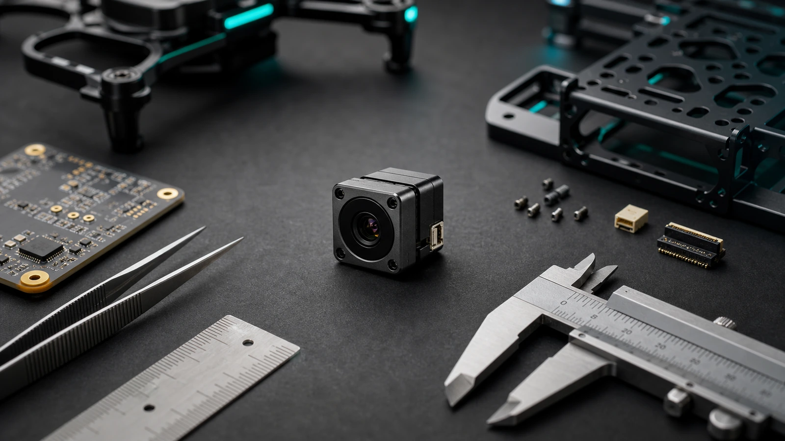
This comprehensive engineering guide breaks down the core trade-offs between closed commercial enterprise platforms and custom OEM LWIR payload architectures. We’ll examine microbolometer detector physics, power-supply requirements, optical calculations, video transmission protocols, and host integration considerations for edge AI on custom airframes.
Table of Contents
- 👉 1. The Commercial Landscape: Turnkey Enterprise Platforms vs. Custom Payloads
- 👉 2. Engineering Realities: Closed DJI Ecosystems vs. Modular OEM Architectures
- 👉 3. Optical Physics & Detector Architecture: 8 μm vs. 12 μm Microbolometers
- 👉 4. Product Showcase: CAMCUDA SuperMini 640 vs. AeroMini 640 Technical Matrix
- 👉 5. Hardware & Communication Pipelines: MIPI, BT.656, CDS3 & GenICam
- 👉 6. Optical Engineering: Athermal Lens Selection and IFOV Calculation
- 👉 7. Edge AI, Target Tracking & Micro-Gimbal Mechanical Stabilization
- 👉 8. Industrial Integration Deep-Dive FAQ
1. The Commercial Landscape: Turnkey Enterprise Platforms vs. Custom Payloads
When you evaluate the commercial market for a DJI with thermal camera, enterprise operators generally select from three hardware tiers:
- ⚙️ Compact Hand-Launch Tier (DJI Mavic 3 Enterprise Thermal – M3T): Packs a 640×512 uncooled VOx microbolometer with a 40 mm equivalent focal length (61° DFOV), paired with a 1/2-inch CMOS wide camera and a 1/2-inch telephoto sensor. It is built for quick-reaction public safety calls and basic utility pole checks.
- ⚙️ All-Weather Mid-Tier (DJI Matrice 30T – M30T): Features an integrated multi-sensor payload combining a 640×512 radiometric thermal core (40 mm equivalent, 61° DFOV), a 48 MP zoom block, a 12 MP wide camera, and a laser rangefinder rated up to 1200 m under DJI’s stated test conditions, housed within an IP55-rated airframe.
- ⚙️ Heavy-Lift Modular Tier (DJI Matrice 350 RTK with Zenmuse H20T / H30T): Uses a supported DJI gimbal payload connection; confirm the aircraft, payload and firmware combination. The Zenmuse H30T has a 1280×1024 thermal sensor, while the H20T has a 640×512 thermal sensor. Both combine thermal imaging with optical cameras for applications such as power-line inspection.
In parallel, platforms from competitors like Autel Robotics (such as the EVO II Dual 640T and EVO MAX 4T) offer competing turnkey thermography solutions. These out-of-the-box birds are excellent for pre-programmed standard flight operations. For custom onboard computer vision, unusual focal lengths, or MAVLink-based flight integration, compare the documented SDK access and supported hardware of the exact platform against an OEM design.
| Architectural Attribute | Turnkey Enterprise Platforms (DJI / Autel) | Custom Modular OEM Payload Systems |
|---|---|---|
| Optical Flexibility | Fixed thermal optics on the selected model; field of view and payload options vary by platform. | Model-specific lens choices: SuperMini 3.7/6.1/8.7/11 mm; AeroMini non-radiometric 4–50 mm options. Match each lens to its own published FOV. |
| Thermal Data Pipeline | Model-specific live video and radiometric image exports; review the camera specification and supported vendor SDK. | Output depends on model and board. SuperMini 640T documents image plus temperature data over CDS3/MIPI; imaging-only cores do not measure temperature. |
| Payload SWaP Budget | Use the complete aircraft and payload mass/power specifications for the selected system. | SuperMini bare core: <3.5 g excluding optics/boards. AeroMini: <20 g excluding lens/flange. Budget the complete lens, electronics and gimbal separately. |
| Onboard Edge Computing | Development and live-video access depend on the aircraft, camera and supported SDK. | Host-side processing is an integration task: verify receiver, driver, data format and measured latency on the chosen companion computer. |
| Avionics Interoperability | Vendor-specific interfaces, applications and SDK support; check the exact supported combination. | PX4/ArduPilot, MAVLink, ROS2, UVC or GenICam support must be established in the complete system; these are not blanket core capabilities. |
For an expanded engineering comparison of commercial aircraft vs. OEM core integration, read our detailed analysis on DJI drones with thermal camera: enterprise models vs custom OEM solutions.
2. Engineering Realities: Closed DJI Ecosystems vs. Modular OEM Architectures
In the shop, we frequently get asked by drone builders and robotics researchers: “Can I just crack open a DJI Mini 4 Pro, Air 3, or Mavic 3 and solder in an LWIR thermal camera module?”
A consumer DJI camera should not be treated as a documented drop-in socket for an OEM thermal core. Here are the integration issues to resolve:
The Firmware, Hardware, and Gimbal Control Barrier
The factory camera, gimbal controller, image processor and aircraft firmware form an integrated system. Matching a connector or identifying a video bus does not establish electrical, firmware or mechanical compatibility. The cited OEM core documentation does not establish a supported camera-swap procedure for the DJI Mini 4 Pro, Air 3 or Mavic 3.
An aftermarket thermal module changes the camera mass, inertia, center of gravity, cabling and power requirements. Those changes require a supported payload interface and engineering validation of the gimbal and aircraft. Do not infer motor-arming behavior, a specific firmware fault or gimbal damage from the OEM core specification alone.
Architectural Approaches for OEM Thermal Integration
For a custom thermal payload, aerospace payload engineers can evaluate two architectural paths:
- ✅ Secondary Standalone Aerial Payload: Evaluate a self-contained thermal pod with its own camera, stabilization, video path and approved power arrangement. Confirm that the host aircraft supports the added payload, mounting location, mass, center of gravity and operating limits. Radiometric feeds require a temperature-measurement model and a validated data path.
- ✅ Custom Open-Standard Airframe Architecture: Teams can design around PX4 or ArduPilot and a companion computer, then choose a documented receiver for the selected LWIR core and interface board. A Jetson-class host, USB adapter or MIPI receiver still needs matching electrical levels, formats, drivers and application software. Measure end-to-end latency and validate telemetry synchronization on the complete system.
To review wiring schematics and pinouts for open-standard UAS builds, check out our guide on thermal camera for drones OEM payloads integration.
3. Optical Physics & Detector Architecture: 8 μm vs. 12 μm Microbolometers
Thermal infrared imaging operates in the Long-Wave Infrared (LWIR) band between 8 μm and 14 μm. Unlike standard CMOS sensors that measure reflected photons, an LWIR detector responds to emitted and reflected thermal radiation; temperature measurement also depends on emissivity and calibration (with total hemispherical gray-body emission idealized as E = εσT4, where T is absolute temperature).
The core of an uncooled thermal camera is the focal plane array (FPA) of microbolometers, typically fabricated from Vanadium Oxide (VOx) due to its high Temperature Coefficient of Resistance (TCR) and low 1/f noise. When incident infrared photons hit the micro-bridge pixels, the bridge heats up, shifting its electrical resistance. The Read-Out Integrated Circuit (ROIC) directly beneath converts these resistance deltas into raw digital thermal counts.
Pixel Pitch Comparison: 8 μm vs. 12 μm Microbolometers
The pixel pitch—the physical center-to-center distance between adjacent detector pixels—affects sensor dimensions, optical requirements, and overall payload SWaP-C metrics; pitch alone does not determine sensitivity or temperature accuracy:
- 🔍 8 μm Pixel Pitch (e.g., CAMCUDA SuperMini 640): Supports a compact detector format. A full 640×512 resolution array occupies an active detector area of just 5.12×4.096 mm. For the same array resolution and field of view, a smaller pitch permits a shorter nominal focal length; actual lens size and image quality depend on the optical design. The SuperMini bare core weighs under 3.5 grams, excluding optics and expansion boards. The complete payload still needs its own mass and power budget.
- 🔍 12 μm Pixel Pitch (e.g., CAMCUDA AeroMini 640): Employs a 7.68×6.144 mm active array for a 640×512 detector. The nominal pixel footprint is 144 μm2, compared with 64 μm2 at 8 μm pitch; these geometric areas do not establish fill factor, NETD or temperature accuracy. AeroMini lists NETD ≤30 mK at 25°C, F/1.0. Its non-radiometric lens choices include focal lengths up to 50 mm; the 25 Hz radiometric version is a separate, currently out-of-stock enquiry configuration with documented 9, 13 and 18 mm lens options.
For detailed selection criteria on detector architectures, read our technical whitepaper on thermal UAS integration: selecting lightweight 640×512 LWIR cores.
4. Product Showcase: CAMCUDA SuperMini 640 vs. AeroMini 640 Technical Matrix
For engineering teams designing high-performance aerial thermal payloads, CAMCUDA delivers two specialized OEM LWIR camera cores optimized for drone and robotic integration.
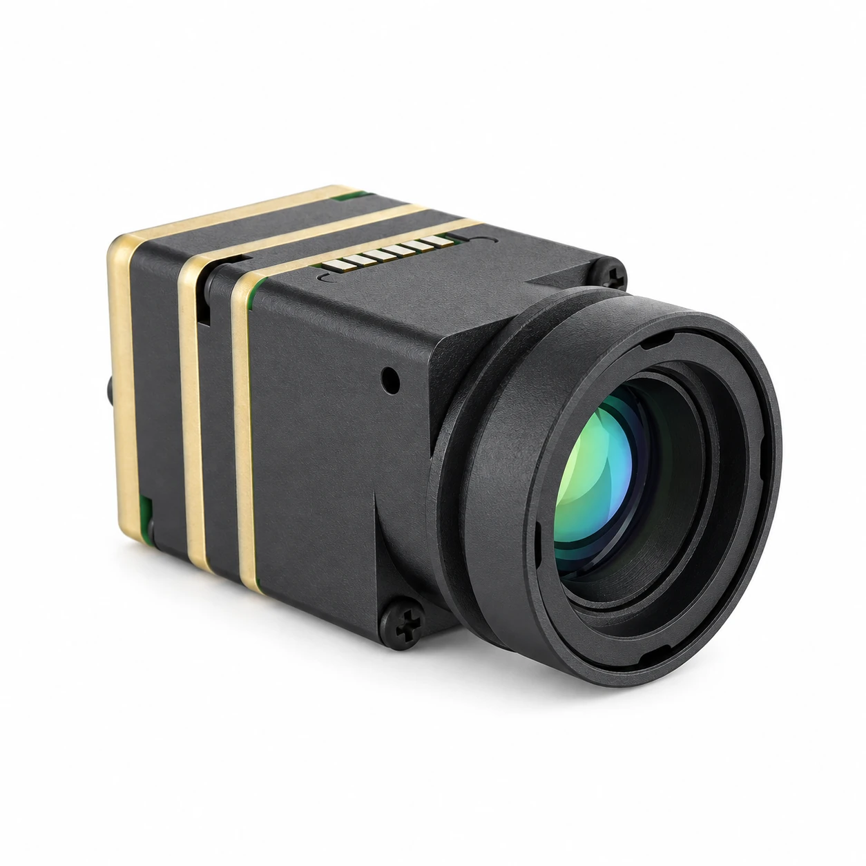
CAMCUDA SuperMini 640 / 640T Ultra-Light LWIR Module
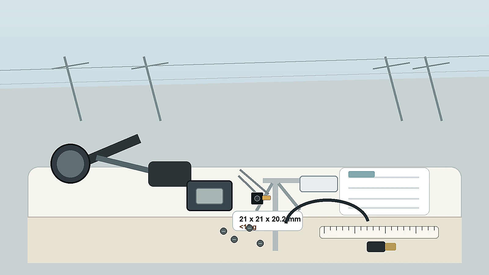
The CAMCUDA SuperMini 640 / 640T resets expectations for SWaP-optimized infrared payloads. Combining an advanced 640×512 uncooled VOx detector with an 8 μm pixel pitch, the SuperMini delivers a core footprint of just 13×13×13.4 mm and a weight under 3.5 grams, excluding optics and expansion boards. The 50 Hz 640 is imaging-only; the 30 Hz 640T is thermographic. Designed specifically for stabilized micro-gimbals, nano-UAVs, soldier-worn sensors, and embedded AI edge vision nodes.
| Resolution & Pitch: | 640 × 512 | 8 μm VOx Microbolometer |
| Core Weight & Dimensions: | <3.5 g | 13 × 13 × 13.4 mm; both exclude optics and expansion boards |
| Sensitivity (NETD): | ≤ 40 mK @ 25°C, F1.0 |
| Models Available: | SuperMini 640 (50 Hz Imaging) | SuperMini 640T (30 Hz Radiometric) |
| Radiometric Range (640T): | −20°C to +150°C and 100°C to +650°C |
| Hardware Interfaces: | Hirose DF40C-30DP-0.4V(51), 30-pin; 1.8 V UART. 640: LVCMOS/BT656; 640T: CDS3. Two-lane MIPI; BT656 and MIPI cannot run simultaneously. CVBS needs an external video buffer; optional TMS6102V100F022 USB board. |
| Power Consumption: | ≤0.5 W typical core power at 25°C, excluding expansion board |
CAMCUDA AeroMini 640×512 Uncooled LWIR Core
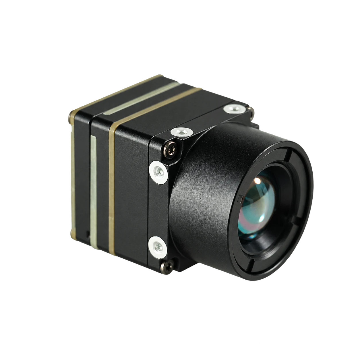
The CAMCUDA AeroMini 640 is a rugged, versatile 12 μm uncooled VOx thermal imaging core engineered for commercial UAV integration, precision agriculture mapping, search and rescue, and industrial inspection. The non-radiometric version has a 60 Hz factory default or 30 Hz factory option, with 4 mm to 50 mm lens choices. Select the USB + CVBS + MIPI tailboard or the separate Type-C + CVBS board, then confirm the actual outputs, control interface, firmware and host. The 25 Hz radiometric version is currently out of stock and enquiry only; no online purchase or pre-order is available. Its interface, measurement details and ordered assembly require confirmation.
| Resolution & Pitch: | 640 × 512 | 12 μm VOx Microbolometer |
| Core Weight & Dimensions: | <20 g | 21 × 21 × 28 mm; both exclude lens and flange |
| Sensitivity (NETD): | ≤30 mK at 25°C, F/1.0 |
| Frame Rate Modes: | Non-radiometric: 60 Hz default / 30 Hz factory option. Radiometric: 25 Hz, currently out of stock; enquiry only. |
| Radiometric Range: | Published radiometric reference: −20°C to +550°C; confirm the range, accuracy, data format and interface for the requested 25 Hz configuration. Documented lenses: 9/13/18 mm; currently out of stock and enquiry only, with no online order or pre-order. This range does not apply to non-radiometric imaging. |
| Video & Control I/O: | Non-radiometric: USB + CVBS + MIPI or separate Type-C + CVBS board. Other listed video/control paths are board/firmware dependent; confirm actual formats, electrical levels and output combinations. Radiometric interface to be confirmed. |
| Operating Voltage & Power: | Illustrated POWER_IN1/POWER_IN2 inputs: 5 V only, never 12 V. Match the supplied board guide; 16-pin/26-pin guides do not cover the separate Type-C board. <0.5 W typical module power at 25°C; kit power may differ. |
5. Hardware & Communication Pipelines: MIPI, BT.656, CDS3 & GenICam
Getting clean, noise-free thermal data into your embedded UAS compute stack comes down to clean PCB routing, strict power filtering, and matching your video transport protocols properly.
Power Supply Integrity and Noise Isolation
Microbolometers detect tiny analog resistance shifts across suspended micro-bridges. If high-frequency electrical noise from brushless Electronic Speed Controllers (ESCs), high-power telemetry transmitters, or buck switching regulators creeps onto the supply rails, it can contribute to horizontal line striping, fixed pattern noise (FPN), or rolling frame artifacts.
When wiring the CAMCUDA SuperMini 640 / 640T through its Hirose DF40C-30DP-0.4V(51) 30-pin connector, follow these power rail design rules:
- ⚠️ MAIN_POWER Rail (3.8 V to 5.2 V, Typical 5.0 V): The maximum specified noise is 10 mV peak-to-peak (p-p). Choose regulation, filtering and local decoupling to meet the published limits; validate rail noise and startup behavior with the complete load.
- ⚠️ +3.3 V Rail (3.28 V to 3.32 V): Requires precise regulation with maximum specified noise of 10 mV p-p.
- ⚠️ +1.8 V Rail (1.78 V to 1.82 V): The published maximum noise is 1 mV RMS across the 1 Hz to 50 kHz band. Select the supply architecture against the manual’s voltage, noise and power-on timing requirements, and verify it during camera operation and motor-load changes.
Digital Video Transport Protocols: MIPI CSI-2, BT.656, and CDS3
OEM thermal cores provide model-specific digital video paths. Receiver timing, data format, buffering and host software determine how those paths behave in the completed payload:
- ⚙️ 2-Lane MIPI CSI-2: SuperMini provides a documented two-lane MIPI path; its BT656 and MIPI outputs cannot operate simultaneously. The host needs a matching receiver, driver and data parser. A CSI connector alone does not establish compatibility with NVIDIA Jetson, Raspberry Pi or Rockchip systems, or prove a latency figure. AeroMini MIPI behavior must be confirmed for its selected board and firmware.
- ⚙️ 8-bit LVCMOS (BT.656): The SuperMini 640 imaging model runs at 50 Hz and documents an 8-bit LVCMOS / BT656 path. The 30 Hz 640T uses its own CDS3 image-plus-temperature format. AeroMini lists BT.656 availability as board and firmware dependent; confirm receiver timing, output mode and concurrent-output limits before selecting an encoder or FPGA frame grabber.
- ⚙️ CDS3 Protocol (Radiometric Temperature Stream): On SuperMini 640T (30 Hz), CDS3 carries YUV422 image data plus temperature data. Its MIPI CSI-2 path uses RAW8 transport packets that the host reassembles, low byte first, into 16-bit image and temperature words. These are not a generic 14-bit raw-count polynomial stream. Appendix 2 of the SuperMini V1.0.0 manual gives ND: T = (TEMP + 7000) / 30 − 273.2 and HD: T = (TEMP − 4600) / 10 − 273.2, with T in °C. Select the formula for the actual output mode; the published −20°C to +150°C and 100°C to +650°C measurement ranges and accuracy conditions still apply. These formulas do not apply to the imaging-only 640.
- ⚙️ Open Industrial Standards (EMVA GenICam Standard): GenICam, USB3 Vision and UVC describe different interface conventions. A USB connector or OEM core does not establish compliance with any of them. Confirm the selected board’s documented protocol, host driver and software support; ROS2, V4L2 and OpenCV integration remains a host-side task. No USB 3.0, GigE or GenICam implementation is established here for these cores.
6. Optical Engineering: Athermal Lens Selection and IFOV Calculation
Optics make or break an aerial thermal payload. LWIR optics require materials and coatings suited to the wavelength band. Germanium (Ge), chalcogenide glass and zinc selenide (ZnSe) are examples; confirm the material, coating and environmental specification of the selected lens.
Because drones experience severe thermal swings during climb and descent, designers may select mechanically athermalized barrels. Athermal lenses combine optical elements and housing materials with offsetting thermal expansion coefficients. Check focus performance over the selected lens assembly’s specified temperature range; a core’s operating-temperature rating does not guarantee lens focus performance.
Mathematical Formulas for Spatial Resolution
To estimate nominal spatial sampling, determine the Instantaneous Field of View (IFOV) and Ground Sample Distance (GSD). The small-angle examples below estimate sampling near the optical axis for a nadir view of a flat plane 50 m away; they do not establish target detection, recognition or identification performance. Actual sampling varies with lens distortion, viewing angle and scene geometry:
IFOV (mrad) ≈ pixel pitch (μm) / focal length (mm)
GSD (m/px) ≈ IFOV (mrad) × distance (m) / 1000
GSD (cm/px) ≈ IFOV (mrad) × distance (m) / 10. The table uses the unrounded pitch/focal-length ratio before rounding the final result.
Athermal Optical Specifications for CAMCUDA SuperMini & AeroMini
| Core Series | Focal Length | Aperture | Field of View (H × V) | IFOV | Nominal GSD @ 50 m | Application Examples (System Validation Required) |
|---|---|---|---|---|---|---|
| SuperMini 640 (8μm) | 3.7 mm | F1.0 | 90.0° × 68.2° | 2.16 mrad | 10.81 cm/px | Obstacle avoidance, indoor navigation, wide-area search |
| SuperMini 640 (8μm) | 6.1 mm | F1.0 | 46.6° × 37.6° | 1.31 mrad | 6.56 cm/px | Search & rescue, agricultural mapping, roof inspection |
| SuperMini 640 (8μm) | 8.7 mm | F1.0 | 40.0° × 32.2° | 0.92 mrad | 4.60 cm/px | Solar panel anomaly detection, powerline inspection |
| SuperMini 640 (8μm) | 11.0 mm | F1.0 | 24.9° × 20.0° | 0.73 mrad | 3.64 cm/px | High-altitude tactical perimeter surveillance |
| AeroMini 640 (12 μm; imaging reference) | 9.0 mm | F1.0 | 48.7° × 38.6° | 1.33 mrad | 6.67 cm/px | Standard general-purpose UAV payload inspection |
| AeroMini 640 (12 μm; imaging reference) | 18.0 mm | F1.0 | 24.2° × 19.5° | 0.67 mrad | 3.33 cm/px | Medium-range pipeline and utility corridor mapping |
| AeroMini 640 (12 μm; non-radiometric) | 35.0 mm | F1.0 | 12.5° × 10.0° | 0.34 mrad | 1.71 cm/px | Long-range standoff surveillance and border patrol |
7. Edge AI, Target Tracking & Micro-Gimbal Mechanical Stabilization
Payload mass affects the airframe and stabilization budget. The CAMCUDA SuperMini 640 bare core is under 3.5 grams, excluding optics and expansion boards. A complete 2-axis or 3-axis gimbal also includes lenses, boards, cables, motors, structure and control electronics; neither its finished mass nor its flight endurance follows from the core mass alone.
In practice, this ultra-light footprint creates opportunities to evaluate during system design:
- ✅ Minimal Inertial Moment: A smaller core can help reduce payload inertia, but motor selection and stabilization depend on the complete assembly, center of gravity and control tuning. Verify disturbance response, vibration and image stability on the intended mount.
- ✅ Measured Edge AI Pipelines: An integrator can evaluate host-side image processing using the selected camera output and a compatible companion computer. The SuperMini 640 imaging rate is 50 Hz; the thermographic 640T is 30 Hz. Validate frame capture, preprocessing, model behavior and total latency on the actual hardware. The core specification does not establish a built-in AI model or validated system latency.
- ✅ System-Level Tracking Integration: Automatic inspection-point tracking requires separate host software, a compatible gimbal controller and validation of the complete control path. Define operator oversight, loss-of-track behavior and measured response during integration. An OEM thermal core alone does not provide MAVLink control, autonomous tracking or flight-control functions.
8. Industrial Integration Deep-Dive FAQ
Can I replace the standard optical camera on a consumer DJI drone with a thermal camera module?
Do not infer specific encrypted-bus behavior, motor-arming lockout or gimbal damage without model-specific evidence.
For custom thermal imaging, evaluate a manufacturer-supported payload path or a separately engineered airframe and payload. A secondary pod still requires approval of the host aircraft’s mounting, power, mass and operating limits.
What are the primary operational differences between buying a DJI Mavic 3 Thermal (M3T) and building a custom OEM thermal drone?
The M3T uses a fixed thermal lens and a documented DJI workflow. Compare its supported image exports and SDK interfaces with your required data path; do not assume that all DJI development access is unavailable.
An OEM build lets the integrator select a core, lens, interface and host, with responsibility for the finished system. SuperMini 640 is 50 Hz imaging-only; 640T is 30 Hz thermographic with documented CDS3/MIPI temperature-data paths. The under-3.5 g mass excludes optics and boards. AeroMini 640 imaging is 60 Hz default or 30 Hz factory configured; its separate 25 Hz radiometric version is currently out of stock, enquiry only, with 9/13/18 mm lenses and an interface to be confirmed. Host drivers, parsing, telemetry, AI software, licensing and system latency require their own review.
How does an 8 μm pixel pitch compare to a 12 μm pixel pitch in aerial thermal applications?
For the same array resolution and field of view, the smaller pitch permits a shorter nominal focal length. Actual lens size, mass and optical quality depend on the design. SuperMini’s under-3.5 g mass is a bare-core specification that excludes optics and boards; it does not establish total payload power or gimbal torque.
The nominal pixel footprints are 144 μm2 at 12 μm and 64 μm2 at 8 μm. These geometric values alone do not establish thermal sensitivity, stability or temperature accuracy. Compare the specified model and test conditions: AeroMini lists ≤30 mK and SuperMini ≤40 mK NETD at 25°C, F/1.0; temperature measurement requires the separate thermographic configuration.
What specific power supply precautions are required to avoid noise artifacts on OEM thermal modules?
When integrating modules like the CAMCUDA SuperMini 640, the system designer must ensure that the MAIN_POWER and +3.3 V rails have no more than 10 mV peak-to-peak noise.
The SuperMini +1.8 V rail is specified at 1.78–1.82 V with 1 mV RMS noise over 1 Hz–50 kHz; +3.3 V is 3.28–3.32 V, and MAIN_POWER is 3.8–5.2 V, typically 5 V. Use the model-matched manual for sequencing and design regulation, filtering and grounding to meet those limits. No single LDO or capacitor recipe is established here. AeroMini uses different board references: illustrated POWER_IN1/POWER_IN2 inputs are 5 V only, and the 16-pin/26-pin guides must not be applied to its separate Type-C board.
📚 References & Further Reading
- Industry Standard: Machine Vision Camera Interoperability Standard: EMVA GenICam Standard
- Commercial Benchmark: Commercial Multi-Sensor UAS Platforms: Autel Robotics
- Related Guide: Thermal Camera for Drones: OEM Payloads Integration Guide
- Related Guide: Thermal UAS Integration: Selecting Lightweight 640×512 LWIR Cores
- Related Guide: DJI Drones with Thermal Camera: Enterprise Models vs Custom OEM Solutions
- AeroMini resources: AeroMini datasheet, model-specific SDK FAQ and AeroMini technical documentation folder. Request the package for the selected board, firmware and host; the 25 Hz radiometric configuration needs separate confirmation.
- SuperMini resources: 640 / 640T product reference and SuperMini Product Manual V1.0.0. Match the imaging or thermographic model before using the interface and conversion instructions.
Technical author: Daniel · Hardware Support
Sales contributors: Vivian, Lena and Sophie