Infrared Drone Camera Modules: Low-SWaP 640 LWIR Cores for UAV Payloads
Infrared Drone Camera Modules: Low-SWaP 640 LWIR Cores for UAV Payloads
Deploying thermal payloads on unmanned aerial vehicles (UAVs) demands a relentless, uncompromising balance between optical performance, image pipeline latency, and ruthless Size, Weight, and Power (SWaP) budgets. For drone OEMs, gimbal builders, and autonomous robotics integrators, off-the-shelf commercial drones hit a brick wall fast. They are closed boxes. Integrating a dedicated bare-core Long-Wave Infrared (LWIR) camera module hands the hardware engineer full architectural control: you pick the optical field of view (FOV), wire zero-latency digital direct buses, and eliminate the dead weight, thermal throttling, and walled-garden firmware of turnkey payloads.
Whether you are piecing together an FPV tactical reconnaissance rig, a stabilized micro-gimbal for long-endurance ISR, or an automated industrial inspection payload, picking the right infrared drone camera core boils down to brass tacks: detector physics, electrical noise tolerance, and optical MTF under wild ambient swings. This engineering guide breaks down modern 640×512 uncooled Vanadium Oxide (VOx) LWIR modules—comparing ultra-dense 8 μm micro-cores against high-photonic-capture 12 μm platforms—so your engineering team can build a rock-solid, airborne thermal vision system without blowing the mass budget.
Table of Contents
- 👉 1. Aerial LWIR Integration Fundamentals: Physics, Pixel Pitch, and Core Architecture
- 👉 2. Solving the SWaP Equation in UAV Micro-Gimbal & Payload Design
- 👉 3. Optical Path Optimization: Athermalized Lenses, IFOV, and Aerial DRI Metrics
- 👉 4. Electrical, Bus, and Video Pipeline Architecture: MIPI, USB, BT.656, and Power Integrity
- 👉 5. Radiometric Telemetry vs. Tactical Thermal Imaging for Unmanned Systems
- 👉 6. Commercial-Off-The-Shelf (COTS) Payload vs. Bare-Core OEM Integration Analysis
- 👉 7. Low-SWaP 640×512 LWIR UAV Core Showcase & Technical Comparison
- 👉 8. Step-by-Step Engineering Integration Guide: Flight Controller & Video Pipeline
- 👉 9. Frequently Asked Questions (Technical Deep-Dive)
1. Aerial LWIR Integration Fundamentals: Physics, Pixel Pitch, and Core Architecture
Thermal vision in the air functions entirely within the 8 to 14 μm Long-Wave Infrared (LWIR) atmospheric window. Here’s the deal: visible CMOS and near-infrared (NIR) sensors are completely hostage to reflected ambient photons or power-hungry active illuminators. LWIR focal-plane arrays (FPAs) do not care about illumination. They measure passive blackbody radiation radiating straight out of targets and terrain. That makes an infrared drone sensor irreplaceable for zero-lux navigation, tracking heat signatures through wildfire smoke, cutting through dust plumes, and identifying targets masked by shadows.
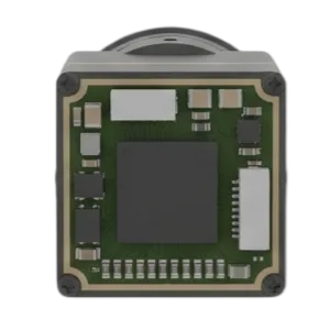
Focal-Plane Array (FPA) Physics: Vanadium Oxide (VOx)
In the shop, you will see two main microbolometer materials: Amorphous Silicon (α-Si) and Vanadium Oxide (VOx). For high-performance aerial systems, VOx wins hands down. VOx delivers a significantly higher Temperature Coefficient of Resistance (TCR) alongside dramatically lower 1/f flicker noise. This translates directly into exceptional thermal sensitivity, measured as Noise Equivalent Temperature Difference:
NETD ≤ 30 to 40 mK at 25°C, F/1.0
Look, an NETD under 40 mK means the core resolves temperature deltas smaller than 0.04°C. That level of sensitivity lets an aerial payload spot faint thermal signatures—like residual tire tracks on hot asphalt, subtle roof moisture leaks under insulation, or a human concealed in dense foliage. Just as critically, higher native raw sensitivity means the onboard Image Signal Processor (ISP) does not have to lean on heavy multi-frame temporal averaging filters. That saves you from the nasty motion ghosting and smear that ruin high-speed FPV tactical reconnaissance passes.
The Impact of 8 μm vs. 12 μm Pixel Pitch on UAV Payloads
The jump down from legacy 17 μm and 12 μm pixel nodes to ultra-dense 8 μm pixel pitch fabrication represents a massive mechanical design win for payload engineers. Shrinking the pixel pitch ripples through every physical aspect of your gimbal assembly:
- ⚙️ Sensor Die Dimensions: An 8 μm 640×512 array drops active sensor real estate down to an astonishing 5.12 × 4.10 mm (approx. 6.55 mm optical diagonal). By comparison, a 12 μm 640×512 array measures 7.68 × 6.14 mm (approx. 9.83 mm diagonal).
- ⚙️ Mass Cascades in the Optical Barrel: Focal length scales directly with sensor size to hold a target Field of View (FOV). An 8 μm core uses a much shorter focal-length lens to achieve the exact same field coverage as a 12 μm sensor. Shorter focal lengths mean smaller front apertures, thinner Germanium or Chalcogenide glass elements, and a massive 50% to 65% drop in total optical barrel mass.
- ⚠️ Diffraction Limits & Fast Apertures: There is no free lunch in physics. Because an 8 μm pixel is roughly the size of the LWIR wavelength itself (8–14 μm), your optics have to run fast (typically F/1.0) with stellar Modulation Transfer Function (MTF) to stop Airy disk blur from washing across adjacent microbolometer wells.
If you are building a micro-gimbal or aerodynamic wing pod, picking between 8 μm and 12 μm comes down to extreme packaging compactness versus maximum raw photonic sensitivity. For a deeper breakdown of these core trade-offs, check out our guide on Thermal Imaging Camera for Drone Payloads: OEM Integration Selection.
2. Solving the SWaP Equation in UAV Micro-Gimbal & Payload Design
Every single gram on a drone payload steals flight time and degrades gimbal kinematics. Whether you are running a fixed-wing endurance platform or a multirotor quad, mass sitting on the end of a gimbal arm demands continuous electrical power to stabilize.
Minimizing Gimbal Inertia & Mechanical Loading
Gimbal motor torque scales directly with payload mass and the square of the distance from the rotational axis ($I = m \cdot r^2$). When your camera module is heavy, your brushless stabilization motors draw high continuous current just holding position against aero-buffeting and airframe vibration.
Dropping in a bare-core thermal module that weighs less than 3.5 grams (like the CAMCUDA SuperMini 640) or under 20 grams (like the CAMCUDA AeroMini 640) slashes rotational inertia. That allows you to use smaller, high-pole-count brushless motors and high-resolution magnetic encoders, locking down stabilization within ±0.01° without burning out motor drivers or fighting structural resonance.
Power Dissipation and Thermal Management
Shoving high-wattage electronics into an unventilated aerodynamic nose cone creates a thermal trap. Uncooled microbolometers measure micro-resistance shifts caused by incoming infrared energy. When ambient temperatures inside the payload enclosure spike uncontrollably, the sensor’s Non-Uniformity Correction (NUC) drifts, causing nasty fixed-pattern noise (FPN), thermal vignetting, and calibration loss.
Cores engineered for ≤ 0.5 W typical power consumption solve this problem natively. You do not need noisy cooling fans or bulky copper heatsinks. A simple conductive heat path from the core’s metal case into an aluminum gimbal arm or airframe mount is all it takes. For teams balancing strict bill-of-materials and mass budgets, read our technical breakdown on Thermal Video Camera Cheap: The Engineer’s Guide to Low-Cost LWIR.
3. Optical Path Optimization: Athermalized Lenses, IFOV, and Aerial DRI Metrics
Drones experience brutal temperature shifts. An airframe can sit on an asphalt tarmac baking at +45°C, launch, and climb into a sub-zero −15°C cruise altitude in a matter of minutes. In the thermal realm, Germanium glass has a notoriously high refractive index temperature coefficient ($dn/dT$). Without proper compensation, that temperature swing will pull the focal point completely off your sensor array, turning your crisp thermal feed into an unusable blur.
Athermalized Optical Design Principles
Motorized autofocus mechanisms add weight, draw power, and introduce mechanical failure points you cannot afford on an aircraft. The proper engineering solution is passive mechanical athermalization. This approach pairs precision Germanium and Chalcogenide glass elements inside a barrel constructed from materials with carefully matched, opposing coefficients of thermal expansion (such as custom aluminum alloys and Invar sleeves). The mechanical structure physically shifts the optical elements as temperatures fluctuate, keeping the focal plane firmly locked onto the VOx microbolometer array from −40°C all the way to +80°C.
Instantaneous Field of View (IFOV) and Aerial DRI Metrics
A camera’s spatial resolving power is governed by its Instantaneous Field of View (IFOV)—the angular slice of space covered by a single pixel:
IFOV (mrad) = Pixel Pitch (μm) / Focal Length (mm)
Smaller IFOV numbers mean you can resolve targets at greater standoff distances. Using the standardized Johnson Criteria, here is how standard athermal optical configurations map out for aerial Detection, Recognition, and Identification (DRI):
| Optical Configuration | Pixel Pitch | Field of View (H × V) | IFOV | Primary UAV Mission Application |
|---|---|---|---|---|
| 3.7 mm F1.0 Athermal | 8 μm | 90.0° × 68.2° | 2.16 mrad | Wide-area situational awareness, low-altitude FPV, collision avoidance |
| 6.1 mm F1.0 Athermal | 8 μm | 46.6° × 37.6° | 1.31 mrad | Close-range infrastructure inspection, structural thermography, tactical SA |
| 8.7 mm F1.0 Athermal | 8 μm | 40.0° × 32.2° | 0.92 mrad | Perimeter security, tactical ISR, mid-range search & rescue |
| 11.0 mm F1.0 Athermal | 8 μm | 24.9° × 20.0° | 0.73 mrad | Long-range target tracking, SAR standoff, high-altitude micro-payloads |
| 9.0 mm F1.0 Athermal | 12 μm | 48.7° × 38.6° | 1.33 mrad | Standard enterprise utility survey, solar farm anomaly mapping |
| 18.0 mm F1.0 Athermal | 12 μm | 24.2° × 19.5° | 0.67 mrad | High-voltage line inspection, wildlife monitoring, border patrol |
| 35.0 mm F1.0 Athermal | 12 μm | 12.5° × 10.0° | 0.34 mrad | Long-range standoff reconnaissance, border surveillance installations |
4. Electrical, Bus, and Video Pipeline Architecture: MIPI, USB, BT.656, and Power Integrity
When wiring bare thermal cores to companion Single Board Computers (SBCs)—such as an NVIDIA Jetson Orin Nano/NX, Raspberry Pi Compute Module 4/5, or custom FPGA hardware—selecting the right interface protocol dictates your total system latency and CPU overhead.
Digital and Analog Video Transport Protocols
- ⚙️ 2-Lane MIPI CSI-2: The gold standard for embedded AI edge processing. Pushing uncompressed pixel frames straight into the host processor’s hardware Image Signal Processor (ISP) over differential MIPI lines bypasses USB driver stack latency completely. This gets you sub-frame end-to-end latency, which is non-negotiable for autonomous tracking and edge Machine Vision algorithms.
- ⚙️ 8-bit LVCMOS / BT.656: A rock-solid, synchronous digital parallel interface. It pairs directly with dedicated hardware H.264/H.265 compression encoders, airborne digital datalinks, and FPGAs without needing complex kernel-level software driver development.
- ⚙️ USB 2.0 (UVC Standard): Standardized plug-and-play video streaming over a simple four-wire link. UVC makes software development straightforward across Linux V4L2, ROS (Robot Operating System), and Windows ground stations.
- ⚙️ Analog CVBS (PAL / NTSC): Modulates analog video straight out to standard 5.8 GHz analog video transmitters (VTX). This setup gives you a simple, ultra-lightweight, zero-latency feed for manual FPV drone piloting where an onboard companion computer is not needed.
Electrical Rail Integrity and Noise Filtering
Microbolometer pixels detect microvolt-level signal variations across their suspended bridge structures. Brushless drone motors and Electronic Speed Controllers (ESCs) dump massive high-frequency switching hash back onto the main DC power bus. If that noise reaches the sensor, it will show up as nasty horizontal banding, rolling lines, and destroyed NETD performance.
To keep the thermal stream clean, your power conditioning network must deliver tightly regulated rails:
- ⚙️ MAIN_POWER Rail: 3.8 V to 5.2 V (5.0 V nominal), holding ripple strictly to ≤ 10 mV peak-to-peak under full dynamic motor load.
- ⚙️ +3.3 V Digital Rail: 3.28 V to 3.32 V, requiring ≤ 10 mV peak-to-peak noise limits.
- ⚙️ +1.8 V Sensitive Core Logic: 1.78 V to 1.82 V, requiring ultra-low noise thresholds (≤ 1 mV RMS across 1 Hz to 50 kHz).
In the shop, always place dedicated low-noise Low-Dropout Regulators (LDOs) and LC filter networks immediately adjacent to the core’s board-to-board connector (such as the Hirose DF40C-30DP).
5. Radiometric Telemetry vs. Tactical Thermal Imaging for Unmanned Systems
Before locking in a purchase order, you have to decide whether your mission requires qualitative visual tracking or quantitative temperature telemetry.
Non-Radiometric / Tactical Imaging Cores
Tactical imaging cores (like the standard SuperMini 640 and AeroMini 640) are tuned specifically for visual clarity and target discrimination. The internal image engine runs dynamic scene equalization, digital detail enhancement (DDE), and aggressive Automatic Gain Control (AGC) to compress the sensor’s raw 14-bit data down to an optimized 8-bit visual stream (such as White Hot, Black Hot, or Ironbow palettes).
These modules run at high refresh rates (50 Hz or 60 Hz), eliminating motion blur and spatial lag during aggressive flight maneuvers. That makes them ideal for perimeter security, night ISR, search and rescue (SAR), and tactical target tracking.
Radiometric / Thermographic Modules
Radiometric cores (such as the SuperMini 640T and AeroMini 640 Radiometric) deliver calibrated, per-pixel temperature telemetry. Instead of outputting purely contrast-stretched 8-bit images, they output full 14-bit or 16-bit linear temperature matrices (or proprietary CDS3 data streams) calibrated against factory blackbody curves across wide ranges (such as −20°C to +150°C and 100°C to +650°C).
Radiometric cores run at 25 Hz to 30 Hz to handle the heavy computational overhead of per-pixel mathematical temperature calibration in real time. This capability is required for solar farm auditing, high-voltage utility inspection, and structural thermography. To compare passive LWIR sensors against active NIR low-light cameras, check out our guide on Drone with Night Vision: Thermal LWIR vs Low-Light Sensor Guide.
6. Commercial-Off-The-Shelf (COTS) Payload vs. Bare-Core OEM Integration Analysis
When engineering an aerial platform, choosing between buying a boxed commercial thermal gimbal or integrating a bare OEM module comes down to capability, weight, and architecture:
| Engineering Parameter | Turnkey COTS Enterprise Gimbal | Bare-Core OEM Integration (CAMCUDA) |
|---|---|---|
| System Mass Profile | Heavy (typically 250 g to 850 g cased) | Ultra-low SWaP (<3.5 g to <20 g bare core) |
| Data Pipeline Control | Proprietary video stream, restricted SDKs | Direct 2-Lane MIPI, raw USB UVC, BT.656, or CVBS |
| Optical Flexibility | Fixed factory lens, unchangeable FOV | Wide choice of athermal optics (3.7 mm to 60 mm) |
| Autonomy & AI Integration | High latency via external HDMI/RTSP capture | Zero-latency direct bus connection to Edge AI SoCs |
| Ground Station Support | Vendor-locked proprietary ground station apps | Native open MAVLink, QGroundControl, and Mission Planner |
| BOM Cost Scalability | High commercial markup, costly replacements | Direct OEM volume economics |
7. Low-SWaP 640×512 LWIR UAV Core Showcase & Technical Comparison
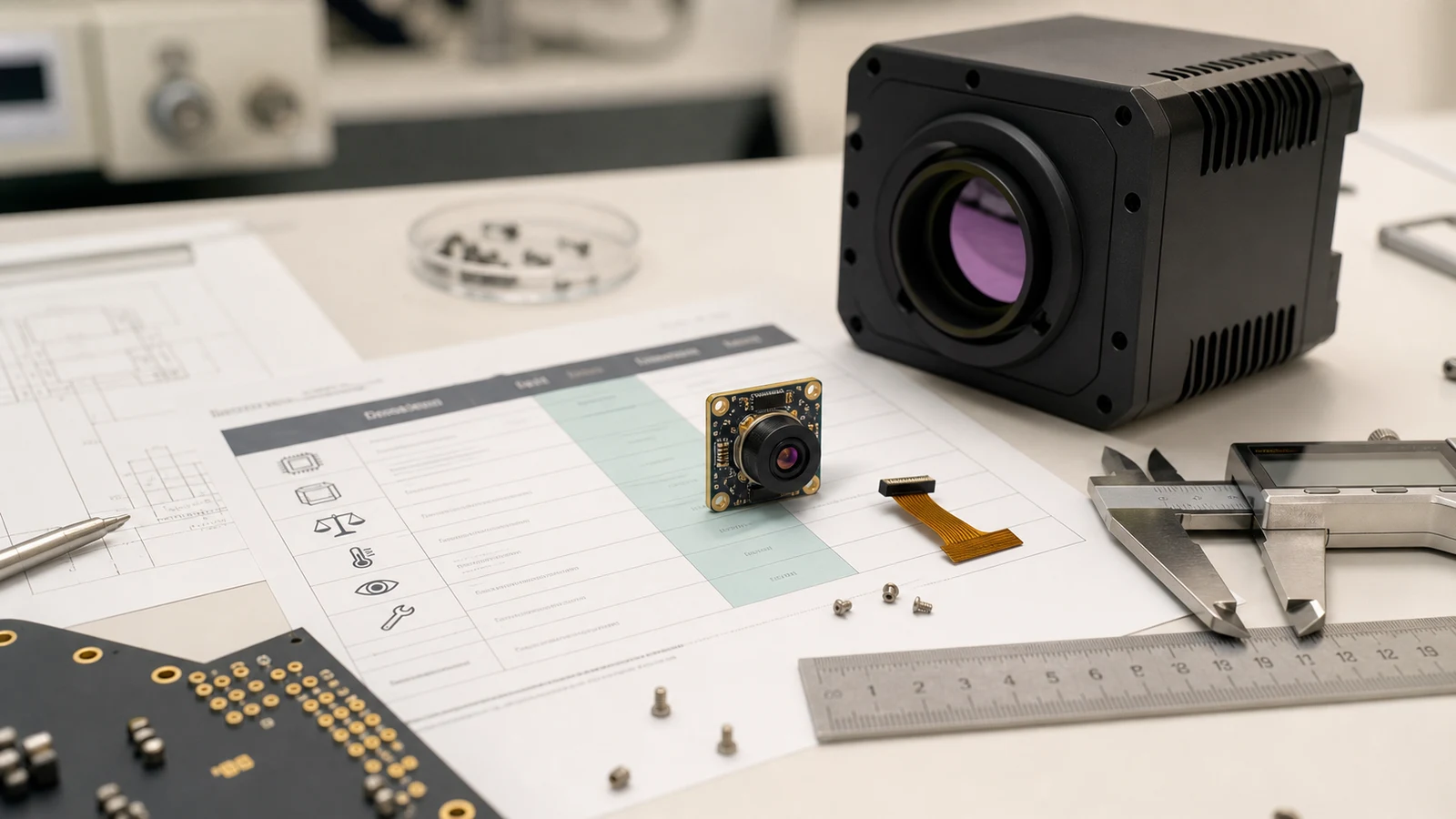
CAMCUDA manufactures two distinct, low-SWaP 640×512 LWIR camera core platforms engineered specifically for airborne integration: the sub-3.5g SuperMini 640 / 640T series and the multi-interface AeroMini 640 platform.
CAMCUDA SuperMini 640 / 640T Ultra-Light LWIR Thermal Camera Module
640 × 512 | 8 μm Pixel Pitch | <3.5 g Bare Core | ≤0.5 W Power
The CAMCUDA SuperMini 640 / 640T sets an industry benchmark for extreme SWaP optimization in tight aerial airframes. Packing an 8 μm uncooled VOx array into an ultra-compact 13 × 13 × 13.4 mm envelope, it delivers full 640×512 resolution while tipping the scales at under 3.5 grams. Engineered for sub-250g UAVs, micro-gimbals, and FPV airframes, the platform is available in two factory models: the 50 Hz imaging SuperMini 640 (with 8-bit LVCMOS/BT656 and 2-lane MIPI), and the 30 Hz radiometric SuperMini 640T (providing per-pixel temperature measurements up to +650°C).
| Detector Architecture | Uncooled VOx Focal Plane Array, 8–14 μm LWIR |
|---|---|
| Thermal Sensitivity (NETD) | ≤40 mK @ 25°C, F1.0 |
| Core Physical Dimensions | 13 × 13 × 13.4 mm (excluding lens and flange) |
| Electrical Connector | Hirose DF40C-30DP-0.4V(51) 30-Pin Receptacle |
| Power Requirements | MAIN_POWER: 3.8–5.2 V (5 V typ.), +3.3 V (≤10 mV p-p), +1.8 V (≤1 mV RMS); Typical Power ≤0.5 W |
| Video Output Modes | 8-bit LVCMOS / BT.656 or 2-Lane MIPI CSI-2 (640: BT656 / 640T: CDS3); Optional USB via expansion board |
| Serial Control | UART (1.8 V logic level) |
| Standard Athermal Lenses | 3.7 mm (90.0°×68.2°), 6.1 mm (46.6°×37.6°), 8.7 mm (40.0°×32.2°), 11.0 mm (24.9°×20.0°) |
| Thermography (640T) | −20°C to +150°C and 100°C to +650°C measurement ranges |
CAMCUDA AeroMini 640×512 Uncooled LWIR USB Thermal Camera Core for UAV Integration
640 × 512 | 12 μm Pixel Pitch | ≤30 mK High Sensitivity | Multi-Interface Payload Ready
The CAMCUDA AeroMini 640 combines high photonic sensitivity with versatile hardware interfacing for commercial drone gimbals and industrial UAV platforms. Built around a 12 μm VOx microbolometer with ≤30 mK sensitivity, it captures subtle thermal gradients in low-contrast environments. The module supports 60 Hz non-radiometric imaging (or 30 Hz factory option) or a 25 Hz radiometric mode (−20°C to +550°C). With expansion board options supporting USB 2.0 (UVC), BT.656, analog CVBS (PAL/NTSC), and RS232/RS422/UART serial control, the AeroMini drops straight into custom multirotor and fixed-wing builds.
| Detector Architecture | Uncooled VOx Focal Plane Array, 8–14 μm LWIR |
|---|---|
| Thermal Sensitivity (NETD) | ≤30 mK at 25°C, F/1.0 |
| Core Physical Dimensions | 21 × 21 × 28 mm (excluding lens and flange) |
| Core Mass (Bare) | <20 g (without lens and flange) |
| Power Requirements | 5 V or 12 V (Interface board dependent); Typical Module Consumption <0.5 W |
| Digital & Analog Video | USB 2.0 (UVC), YUV, BT.656, CVBS (PAL/NTSC selectable) |
| Serial Communication | UART, RS232, RS422 (Board-dependent) |
| Broad Optical Portfolio | 4 mm, 7 mm, 9 mm, 13 mm, 15 mm, 18 mm, 25 mm, 35 mm, 50 mm, 60 mm athermal lenses |
| Operating Envelope | −40°C to +80°C Operating; −50°C to +85°C Storage; 5–95% Non-condensing humidity |
Comprehensive Side-by-Side Engineering Matrix
| Specification | CAMCUDA SuperMini 640 / 640T | CAMCUDA AeroMini 640 Series |
|---|---|---|
| Resolution & Sensor Type | 640 × 512 uncooled VOx LWIR | 640 × 512 uncooled VOx LWIR |
| Pixel Pitch | 8 μm (Ultra-miniature active area) | 12 μm (High photonic capture) |
| Thermal Sensitivity (NETD) | ≤40 mK @ 25°C, F1.0 | ≤30 mK @ 25°C, F1.0 |
| Core Dimensions & Mass | 13 × 13 × 13.4 mm | <3.5 g | 21 × 21 × 28.0 mm | <20.0 g |
| Frame Rates Supported | 640: 50 Hz | 640T: 30 Hz | Non-radiometric: 60 Hz / 30 Hz | Radiometric: 25 Hz |
| Primary Digital Output | 2-Lane MIPI CSI-2, 8-bit LVCMOS / BT.656 | USB 2.0 (UVC), BT.656, Analog CVBS |
| Typical Power Consumption | ≤0.5 W | <0.5 W |
| Thermographic Range | 640T: −20°C to +150°C / 100°C to +650°C | Radiometric: −20°C to +550°C |
8. Step-by-Step Engineering Integration Guide: Flight Controller & Video Pipeline
Follow this practical bench workflow to integrate an uncooled 640×512 LWIR core into an autonomous UAV platform:
Step 1: Mechanical Enclosure & Optical Window Integration
- ⚙️ Secure the bare module directly into your inner gimbal frame using the chassis mounting bosses. Never torque down against the lens barrel threads.
- ⚙️ For sealed IP67 enclosures, fit an anti-reflective (AR) coated Germanium (Ge) or Zinc Sulfide (ZnS) optical protective window. Do not use standard glass, acrylic, or polycarbonate—they are completely opaque to LWIR wavelengths.
- ⚙️ Lay down a high-conductivity thermal interface pad (1.5 to 2.0 W/m-K) between the camera’s rear metal case and the aluminum gimbal bracket to establish a solid conductive thermal path.
Step 2: Electrical Interconnection and Power Conditioning
- ⚙️ SuperMini 640: Fabricate a flexible flat cable (FPC) with a Hirose DF40C-30DP mating connector. Route differential MIPI CSI-2 traces with strict 100 Ω differential impedance, matching intra-pair line lengths to within ±0.1 mm.
- ⚙️ AeroMini 640: Use the standard USB 2.0 expansion header for connection to your onboard companion computer, or solder the CVBS line directly into your analog 5.8 GHz video transmitter.
- ⚙️ Power the core via a dedicated step-down regulator followed by an ultra-low-noise LDO. This keeps motor switching noise away from sensitive analog sensor rails (≤ 10 mV p-p noise floor).
Step 3: Software Video Pipeline Initialization
On your embedded Linux computer (such as an NVIDIA Jetson running JetPack / Ubuntu), fire up the UVC or MIPI V4L2 video ingestion pipeline. Verify the stream using GStreamer:
# Ingest 640x512 30fps thermal video stream via V4L2 and render locally
gst-launch-1.0 v4l2src device=/dev/video0 ! \
  video/x-raw,format=YUY2,width=640,height=512,framerate=30/1 ! \
  videoconvert ! autovideosink
Step 4: Flight Controller Telemetry and Ground Station Bridging
- ⚙️ Connect a UART serial link from the camera core to a TELEM port on your flight controller running ArduPilot or PX4.
- ⚙️ Map MAVLink camera commands (
MAV_CMD_DO_DIGICAM_CONTROL, color palette toggles, digital zoom steps, manual NUC shutter calibration) to pilot RC transmitter switches. - ⚙️ Transmit the digitized thermal video with embedded temperature metadata over RTSP to ground control stations, validating real-time rendering inside QGroundControl.
9. Frequently Asked Questions (Technical Deep-Dive)
Why should UAV engineers integrate a standalone thermal core instead of buying ready-to-fly enterprise infrared drones?
What is the primary difference between radiometric and non-radiometric infrared drone cameras?
How do you solve SWaP (Size, Weight, and Power) constraints when designing micro-gimbal drone payloads?
📚 References & Further Reading
- Industry Standard: QGroundControl
- Industry Standard: Wikipedia – Machine Vision
- Related Guide: Thermal Imaging Camera for Drone Payloads: OEM Integration Selection
- Related Guide: Thermal Video Camera Cheap: The Engineer’s Guide to Low-Cost LWIR
- Related Guide: Drone with Night Vision: Thermal LWIR vs Low-Light Sensor Guide