Drones with Thermal Camera: OEM Guide to LWIR Cores & AI UAV Integration
Drones with Thermal Camera: OEM Guide to LWIR Cores & AI UAV Integration
Civilian unmanned aerial systems (UAS) used for search and rescue, environmental observation, and infrastructure inspection depend on a well-matched sensing payload. Building drones with thermal camera systems means balancing size, weight, power, and cost (SWaP-C) against optical resolution, video transport, and onboard processing. LWIR imaging can reveal thermal contrast without visible illumination, but weather, obscurants, viewing distance, and scene contrast still limit what the system can resolve. Temperature measurement also requires a documented radiometric configuration; a useful thermal image alone does not establish measurement accuracy.
Commercial thermal gimbals and OEM camera cores solve different integration problems. A packaged payload may simplify stabilization, software support, and deployment, while an OEM core may offer more flexibility in optics, mounting, and processing. Access to raw frames, control commands, and a supported software development kit (SDK) depends on the exact product and firmware. Pairing visible and thermal cameras with edge AI can support inspection workflows, but it does not by itself provide sensor fusion, custom model deployment, or flight-controller compatibility.
This OEM guide covers uncooled microbolometers and cooled MWIR detectors, optical selection, visible/thermal processing, flight-controller interface checks, and power delivery. The current hardware comparison uses AI VisionCube ST Pro with 1 TOPS and DT Pro with 6 TOPS. These published compute ratings identify configuration differences; they are not measured inference speeds or end-to-end latency guarantees.
For compact inspection multirotors and fixed-wing survey platforms, the goal is a verifiable integration plan: select the imaging channels, request matching electrical and mechanical documents, budget the complete payload, and validate a sample on the bench before flight. A sub-250g design must account for the complete aircraft and its installed payload, rather than treating a camera-board weight as the finished system mass.
Table of Contents
- 👉 1. Architectural Overview: How LWIR Thermal Cores Empower Next-Gen UAV Systems
- 👉 2. Physics & Sensor Selection: Uncooled VOx Microbolometers vs. Cooled MWIR
- 👉 3. Dual-Spectrum Sensor Fusion & Edge AI Tracking: 1 TOPS and 6 TOPS Configurations
- 👉 4. Flight Controller Interfacing: Verifying CRSF, MAVLink, ArduPilot, & Betaflight Support
- 👉 5. SWaP-C Optimization & Optical Engineering in Compact Airframes
- 👉 6. OEM Hardware for Drones with Thermal Camera Systems: Comparing 1 TOPS and 6 TOPS
- 👉 7. Pre-Flight Hardware Harnessing, Power Conditioning, and Bench Validation
- 👉 8. Technical FAQ for Aerospace & Robotic Systems Engineers
1. Architectural Overview: How LWIR Thermal Cores Empower Next-Gen UAV Systems
Visible cameras depend on reflected light and can lose contrast in darkness or obscurants. An LWIR camera, commonly operating in the 8–14 µm atmospheric window, senses infrared radiation from the scene. The detected signal includes emission from real surfaces and reflected background radiation, modified by the atmosphere and optics. Thermal imaging can help in some smoke or low-light conditions; it does not reliably see through dense fog, rain, dust, vegetation, or solid barriers. See FLIR’s explanation of thermal imaging in fog and rain, and test the intended scene conditions.
In an uncooled microbolometer, an infrared-transmissive lens forms an image on a focal plane array (FPA). Absorbed radiation changes each sensing element’s temperature and electrical resistance. Readout circuitry and conversion electronics produce digital image data. Non-uniformity correction (NUC) compensates for variations among pixels and operating conditions; its implementation may include shutter-based updates. NUC improves image uniformity but does not, by itself, turn image counts into calibrated temperature measurements.
Sending compressed video to a ground control station adds processing and transport stages whose delay depends on encoding, link conditions, buffering, and display settings. Onboard inference can reduce dependence on transmitting every frame for analysis, while still requiring a suitable operator link and clear failure behavior. Measure sensor-to-result and sensor-to-display latency separately under representative conditions instead of assigning a universal latency to either architecture.
A camera’s output frame rate, the AI model’s inference rate, and the flight controller’s update rate are different quantities. Select an interface that the camera actually exposes, then confirm host support, timestamps, buffering, and data formats. The current VisionCube Pro thermal-camera specification lists USB, while complete processing-board interface details require configuration-specific documentation. The CAMCUDA product catalog can help identify candidate hardware, but a listing alone is not an integration or flight-acceptance test.
2. Physics & Sensor Selection: Uncooled VOx Microbolometers vs. Cooled MWIR
Detector choice affects optical design, payload mass, power, and stabilization requirements. A common comparison for UAV imaging is uncooled LWIR microbolometers versus cooled MWIR photon detectors. These are useful categories rather than an exhaustive classification: detector technologies also operate in other spectral bands, and operating temperature depends on the specific design. Compare complete camera assemblies under stated test conditions.
Vanadium Oxide (VOx) vs. Amorphous Silicon (a-Si)
Vanadium oxide (VOx) and amorphous silicon (a-Si) are sensing materials used in uncooled microbolometers. Material choice alone does not establish image quality. Compare detector noise, thermal response, pixel pitch, optics, readout electronics, processing, and the conditions attached to the published specification:
- ✅ Vanadium Oxide (VOx): Absorbed infrared energy produces a measurable resistance change. A VOx label does not establish a particular NETD, response time, or radiometric accuracy. Request the exact camera’s specifications and test conditions, including lens f-number, scene temperature, and frame rate.
- ⚙️ Amorphous Silicon (a-Si): This is another established microbolometer technology. It should not be dismissed as inherently slow or noisy compared with every VOx detector. Evaluate the finished device’s sensitivity, response time, uniformity, and image processing for the application; do not infer the VisionCube detector material from its resolution.
Uncooled LWIR (8–14 µm) vs. Cooled MWIR (3–5 µm)
Cooled MWIR cameras commonly use photon detectors with a cryocooler to reduce detector noise. Detector composition and cooling design determine the operating temperature, cooldown interval, electrical demand, and service requirements. Cooling does not imply a universal 77 K operating point or a fixed payload weight. Uncooled LWIR cameras avoid a detector cryocooler, but still require electronic startup, stabilization, and image correction. The comparison below describes engineering trade-offs rather than guaranteed numerical ranges for either class.
| Engineering Attribute | Uncooled LWIR Microbolometer | Cooled MWIR Photon Detector |
|---|---|---|
| Spectral Band | Commonly 8–14 µm; confirm the model | Commonly 3–5 µm; confirm the model |
| Thermal Sensitivity (NETD) | Compare the model value and optical/test conditions | Compare the model value and optical/test conditions |
| Power Consumption | Budget detector, electronics and processing; no cryocooler | Include detector electronics, cooler startup and steady-state load |
| Total Payload Weight Envelope | Include lens, board, enclosure, harness and mounting | Include optics, cooler, electronics, enclosure and mounting |
| Startup / Stabilization Time | Electronic startup, stabilization and NUC are model-dependent | Electronic startup plus detector cooldown are model-dependent |
| MTBF (Operational Reliability) | Use the model’s stated reliability conditions; consider shutter operation | Check cooler lifetime, maintenance and the stated reliability conditions |
| Target Airframe Class | Often suited to weight- and power-constrained inspection UAVs | Assess against the aircraft’s complete mass, power and cooling budget |
A 640 × 512 thermal imager can be a useful option for civilian UAV inspection, but resolution alone does not establish range, sensitivity, startup time, or aircraft suitability. If ground personnel also need a thermal view, specify a complete handheld observation device separately, including display, battery life, ergonomics, environmental protection, and any required recording or sharing workflow. Matching pixel counts do not prove identical detector architecture or ground-to-air interoperability. See the OEM core versus handheld thermal-imager selection guide for that distinction.
3. Dual-Spectrum Sensor Fusion & Edge AI Tracking: 1 TOPS and 6 TOPS Configurations
Visible and thermal images offer complementary information for civilian inspection and observation. Visible imagery can provide texture and context, while thermal imagery can reveal contrast in darkness. Thermal contrast can weaken when an object and its background have similar apparent radiance, including some dawn or dusk conditions. Combining channels may improve interpretation, but it does not eliminate obscuration or guarantee continuous tracking. ST Pro’s 1 TOPS and DT Pro’s 6 TOPS are published processing ratings, not demonstrations of particular AI workloads.
Multi-Spectrum Alignment and Fusion
Visible and thermal cameras may differ in position, distortion, resolution, field of view, and exposure timing. Registration requires calibration and an appropriate geometric model. A single homography is not a universal correction for scenes at varying depths because parallax changes with distance. Treat the following as integration concepts to verify, rather than undocumented VisionCube functions:
- ⚙️ Scaling, Calibration & Registration: Map each image using its calibrated intrinsics and the cameras’ relative pose. Resizing alone does not remove lens distortion or parallax. Check alignment over the intended working distances and account for timing differences between visible and thermal streams.
- ⚙️ Edge-Based Fusion: An implementation may overlay visible edges on a thermal image to aid interpretation. That requires documented processing and calibration, and the overlay can become misleading if registration is poor. Do not treat this general technique as a confirmed VisionCube feature.
- ⚙️ Picture-in-Picture (PIP): The VisionCube brochure lists picture-in-picture support. PIP presents two views and does not establish pixel-level fusion, synchronized inference, or automatic confidence switching. Verify available layouts, channel control, and behavior in low light for the selected hardware and firmware.
Deep Learning Object Detection and Tracking
Edge-AI evaluation should define the model, input size, numeric precision, dataset, and acceptance criteria. A TOPS rating counts nominal operations per second; it cannot be converted directly into frames per second without workload and implementation details:
- ✅ Object Detection: Benchmark the intended model with representative inspection imagery. Record precision, recall, inference throughput, and complete capture-to-result latency, including preprocessing and data transfer. Quantization and hardware acceleration can change both accuracy and performance.
- ✅ Tracking: A tracker estimates object continuity across frames. Occlusion, abrupt motion, low contrast, glare, and similar-looking objects can cause missed tracks or identity switches. A second imaging channel may help only when the implementation and conditions support it; validate both failure and recovery behavior.
- ✅ Reacquisition: Motion prediction can estimate where an obscured object might reappear, but it cannot observe through an opaque obstacle or guarantee that a recovered detection is the same object. Require confidence handling, loss-of-track status, and a defined operator response instead of relying on demonstration annotations as specifications.
4. Flight Controller Interfacing: Verifying CRSF, MAVLink, ArduPilot, & Betaflight Support
Camera integration and aircraft control are separate engineering tasks. An inspection payload may simply supply images to an operator; any transfer of detections or pointing requests to a flight computer requires a documented interface and a validated control design. Keep timestamps, reference frames, stale-data handling, and operator override explicit. No flight-controller protocol or autonomous-flight capability is established for VisionCube by the current public specification.
Protocol Mechanics: CRSF vs. MAVLink
Before selecting a protocol, obtain the exact model and firmware documentation. A UART connector, camera interface, or dedicated AI interface does not by itself identify the supported message format:
- ⚙️ CRSF (Crossfire Protocol): CRSF carries RC control and telemetry in compatible systems. Its serial electrical requirements, speed, frame types, and device roles must match at both ends. Do not assume that a vision board emulates an RC receiver, accepts control-channel overrides, or achieves a particular command latency without a documented implementation and bench results.
- ⚙️ MAVLink: Message semantics matter.
VISION_POSITION_ESTIMATErepresents a pose estimate,LANDING_TARGETdescribes a landing target, andGIMBAL_MANAGER_SET_PITCHYAWrequests gimbal orientation or rates. They are not interchangeable containers for a bounding-box offset. Confirm the camera or companion computer’s supported messages, coordinate frames, timestamps, and the receiving autopilot’s behavior.
Pointing Geometry and Control Validation
For a calibrated pinhole model after distortion correction, a horizontal image coordinate u gives an approximate line-of-sight angle θx = arctan((u − cx)/fx), where cx and fx are in pixels. A vertical angle uses the corresponding calibrated quantities and axis convention. Converting that line of sight into a gimbal or aircraft command also needs camera pose, coordinate transforms, timing, control limits, and validated failure behavior. It is not a direct connection from image error to a motor PID loop, and high camera frame rate alone does not establish stable control.
5. SWaP-C Optimization & Optical Engineering in Compact Airframes
Payload mass affects flight endurance and balance, but the relationship depends on the airframe, battery, flight profile, and aerodynamics. Optical selection also changes lens mass, field of view, mounting requirements, and center of gravity. Budget the complete installation, including cables, regulation, cooling, enclosure, and any gimbal or vibration isolation.
Optical Material Selection for LWIR (8–14 µm)
Ordinary visible-camera glass is generally unsuitable as a transmitting lens or protective window across the LWIR band. Select an infrared optical material and coatings with documented transmission over the required wavelength range. Environmental durability, reflection losses, lens geometry, and focus stability matter alongside material choice:
- 🔍 Germanium (Ge): Germanium is widely used for LWIR optics and has a high refractive index. Its density and temperature-dependent optical properties affect mass and focus stability. An athermalized design must account for the whole optical and mechanical assembly; choosing germanium alone does not guarantee low aberration or stable focus.
- 🔍 Chalcogenide Glass: These infrared glasses can support molded aspheric optics; SCHOTT’s infrared-material data illustrates composition-specific properties. Density, transmission, thermal properties, manufacturing cost, and environmental durability vary by composition. Compare the actual material and lens design instead of assuming every chalcogenide lens is lighter, cheaper, or less temperature-sensitive than every germanium lens.
DRI Planning and Johnson’s Criteria
Detection, recognition, and identification (DRI) describe different observation tasks. Johnson-style criteria are historical task-performance estimates under defined conditions, not universal pixel-count guarantees. Pixel thresholds depend on the adopted convention, target, contrast, optics, atmosphere, display, observer, and required probability; they also do not establish an AI model’s detection accuracy:
- ✅ Detection: Establish that an object is present and distinguishable from its background. State the assumed target dimension and required probability before estimating a range.
- ✅ Recognition: Determine the object’s broad class using sufficient resolved detail. The required sampling depends on the class distinction and observation conditions.
- ✅ Identification: Resolve the attributes required for a more specific identification task. It requires a defined task and evidence beyond an unqualified pixel threshold.
For a small-angle sampling estimate, R ≈ (H × f)/(N × p), with target dimension H and range R in meters, and focal length f and pixel pitch p in matching units. Taking H = 2.3 m, f = 9.1 mm, p = 0.012 mm, and an illustrative N = 3 pixels gives R ≈ 581 m. That is a three-pixel geometric projection, not a demonstrated detection range or a recommendation for a DRI threshold. Use the thermal imaging calculator with explicit assumptions, then validate optics, contrast, atmosphere, and the intended observation task.
6. OEM Hardware for Drones with Thermal Camera Systems: Comparing 1 TOPS and 6 TOPS
The current CAMCUDA AI VisionCube Visible & Thermal Camera Modules listing includes two 640 × 512 thermal configurations: ST Pro combines a single visible camera with 1 TOPS processing, while DT Pro combines dual visible cameras with 6 TOPS. Both list 1920 × 1080 visible output at 30 Hz and 640 × 512 thermal output at 50 Hz. Select the exact configuration before requesting a quotation, integration documents, or a sample.
The table separates published component specifications from items requiring confirmation. The current brochure does not establish CPU architecture, measured inference latency, simultaneous track counts, guaranteed tracking speed, or flight-stack compatibility. Component dimensions and mass exclude parts where stated and must not be treated as complete kit values.
| System Specification | AI VisionCube DT Pro (6 TOPS) | AI VisionCube ST Pro (1 TOPS) |
|---|---|---|
| Edge AI Processing Compute | 6 TOPS published rating; benchmark the intended workload | 1 TOPS published rating; benchmark the intended workload |
| Visible Camera Architecture | Dual visible: wide-angle and telephoto | Single visible |
| Thermal Detector Resolution | 640 × 512 pixels; detector material not specified | 640 × 512 pixels; detector material not specified |
| Thermal Spectral Band & Pitch | 8–14 µm LWIR; 12 µm pixel pitch | 8–14 µm LWIR; 12 µm pixel pitch |
| Thermal Frame Rate | 50 Hz published camera output | 50 Hz published camera output |
| Thermal Focal Length & FOV | 9.1 mm; 45.9° H × 36.9° V | 9.1 mm; 45.9° H × 36.9° V |
| EO Visible Output | 1920 × 1080 at 30 Hz | 1920 × 1080 at 30 Hz |
| Visible Optics & Field of View | 3.9 mm wide-angle: 72° H × 45° V; 12 mm telephoto: 26° H × 15° V | 4 mm: 69° H × 42° V |
| Visible Camera Dimensions | 40.8 × 25 × 26 mm | 19 × 19 × 30 mm |
| Thermal Camera Dimensions | 26 × 26 × 21.1 mm, excluding lens and connectors | 26 × 26 × 21.1 mm, excluding lens and connectors |
| Component Weight References | Board: 43.8 g; thermal camera: ≤23 g excluding lens and connectors; not complete kit mass | Board: 43.8 g; thermal camera: ≤23 g excluding lens and connectors; not complete kit mass |
| Model / SDK Documentation | Request supported model formats, SDK and firmware revision | Request supported model formats, SDK and firmware revision |
| Thermal Camera Interface | USB; obtain matching connector, PIN and data-format documentation | USB; obtain matching connector, PIN and data-format documentation |
| Tracking & Display Modes | PIP listed; fusion, tracking and latency require verification | PIP listed; fusion, tracking and latency require verification |
| Flight Controller Protocols | CRSF / MAVLink and flight-stack compatibility not established | CRSF / MAVLink and flight-stack compatibility not established |
| Operating Input Voltage | 9–16 V board input; verify polarity, current and transient limits | 9–16 V board input; verify polarity, current and transient limits |
| Board Dimensions & Mounting | 38 × 38 × 29 mm; mounting: 25.5 × 25.5 mm | 38 × 38 × 29 mm; mounting: 25.5 × 25.5 mm |
| Dedicated AI Interface | DT Pro has a dedicated AI interface; request its exact electrical and protocol specification | Do not assume the DT Pro dedicated AI interface applies to ST Pro |
AI VisionCube DT Pro: Dual Visible, 640 Thermal, 6 TOPS
AI VisionCube DT Pro combines wide-angle and telephoto visible cameras with a 640 × 512 thermal camera and a published 6 TOPS processing rating. Its visible output is 1920 × 1080 at 30 Hz; thermal output is 50 Hz. This provides a configuration to evaluate for civilian inspection and observation, without establishing measured AI throughput, fusion behavior, or automatic aircraft control.
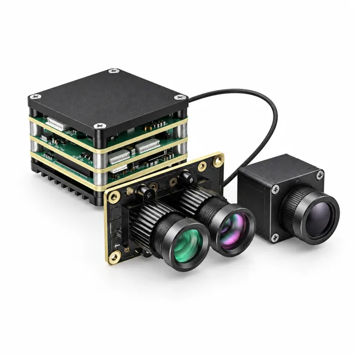
DT Pro has a dedicated AI interface. Obtain the connector and PIN definition, electrical levels, protocol, supported commands, and firmware revision for that interface before designing a harness or host application. This statement applies specifically to DT Pro and should not be generalized to other D-family models. The current public listing does not provide a verified configuration-matched PIN/PDF, SDK package, or CAD download; request those documents from CAMCUDA and verify them against the supplied unit.
View AI VisionCube DT Pro Configuration ➔
AI VisionCube ST Pro: Single Visible, 640 Thermal, 1 TOPS
AI VisionCube ST Pro combines one visible camera with 1 TOPS processing and a 640 × 512 thermal camera. The visible camera lists a 4 mm lens with a 69° H × 42° V field of view; the thermal camera lists 9.1 mm optics and 45.9° H × 36.9° V. Compare this single-visible arrangement with DT Pro’s wide-angle and telephoto arrangement against the inspection task and installation constraints.
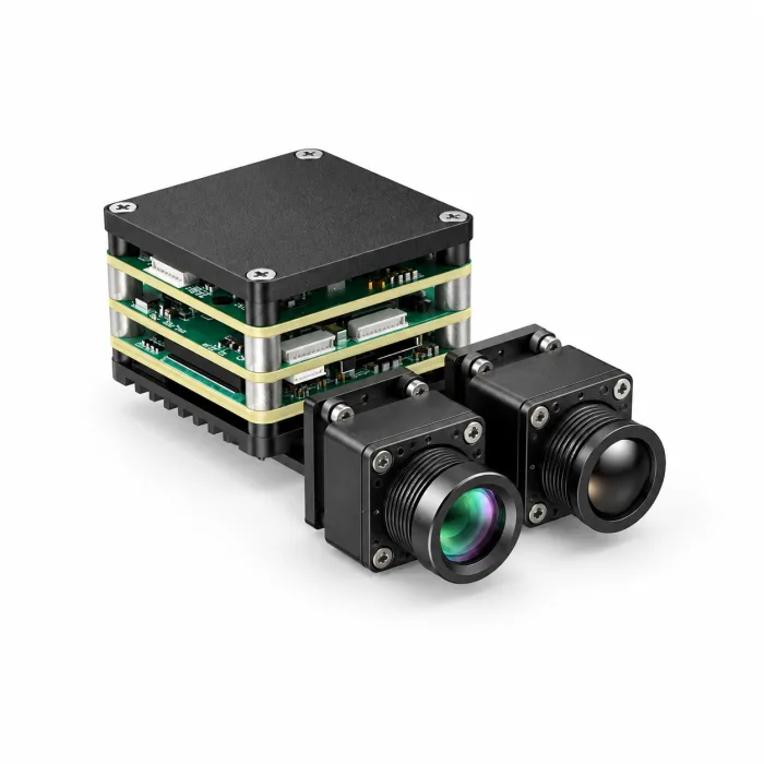
The published common board reference is 38 × 38 × 29 mm with 25.5 × 25.5 mm mounting and a board weight of 43.8 g. The Pro thermal-camera weight is ≤23 g excluding lens and connectors; neither value is complete payload mass. Request the ST Pro assembly drawing, connector/PIN documentation, supported software, and full supplied bill of materials. A USB thermal-camera entry does not establish UVC operation, raw radiometric access, or the processing board’s complete video and control interfaces.
View AI VisionCube ST Pro Configuration ➔
7. Pre-Flight Hardware Harnessing, Power Conditioning, and Bench Validation
Bench testing should establish reliable power, data transport, image quality, and temperature behavior before a flight trial. Record the exact model, firmware, host software, cables, and power source used so results can be repeated. Treat the checklist below as integration work to complete for the selected configuration:
Essential OEM Pre-Flight Checklist
- ⚙️ Regulated Power Delivery: The VisionCube board reference specifies 9–16 V input. Select a regulator for the measured startup and steady-state current, and confirm polarity, protection, connector limits, and allowed ripple. A battery pack must be assessed at its fully charged voltage and under transients; do not infer compatibility from nominal pack voltage. Check the rail under representative electrical loads using appropriate bench safety procedures.
- ⚙️ Thermal Dissipation & Airflow: An uncooled detector avoids a cryocooler, but electronics still generate heat. A TOPS rating is not a power-dissipation specification. Follow the board’s approved thermal design and measure temperature during sustained processing at the expected ambient conditions. Verify that mounting, insulation, and any heat spreader avoid shorts and do not distort the optics.
- ⚙️ Signal Integrity & Harnessing: Use the specified cable assembly, pinout, length limits, strain relief, and grounding scheme. Keep high-speed camera cables clear of noisy power wiring and transmitter equipment as the installation permits. Do not improvise conductive shielding tape around exposed electronics; validate any shielding and termination against the interface guidance and test image continuity with relevant equipment operating.
- ⚙️ Interface and Flight-Stack Validation: Request the matching VisionCube electrical/PIN PDF, protocol specification, SDK and examples, and mechanical CAD or drawing. Confirm which files apply to the exact ST Pro or DT Pro revision. Bench-test documented image and control functions before any aircraft connection. Check supported ArduPilot, PX4, or Betaflight versions only where an actual integration is documented; define stale-data handling and operator override.
- ⚙️ Radiometric Boundary: The current VisionCube brochure does not specify calibrated temperature-measurement range or accuracy. Do not present ST Pro or DT Pro as a radiometric measurement system on that basis. Quantitative inspection needs a supported calibrated configuration, accessible measurement data, and documented corrections for emissivity, reflected apparent temperature, atmosphere, and optics; AGC and NUC alone are insufficient.
- ⚙️ Data Governance: Define access, retention, and sharing for inspection imagery and location records according to the deployment’s applicable requirements. Review the manufacturer’s privacy policy when submitting a project inquiry; that policy does not certify the compliance of your aircraft or data pipeline.
8. Technical FAQ for Aerospace & Robotic Systems Engineers
Can I integrate an uncooled thermal camera module into lightweight or custom sub-250g drone platforms?
It may be possible, but suitability depends on the complete aircraft mass, power, balance, and operating requirements. The current VisionCube board reference is 43.8 g; its Pro thermal-camera weight is ≤23 g excluding lens and connectors. Add the visible camera, optics, wiring, regulator, enclosure, mounts, battery implications, and any stabilization hardware before checking a sub-250g target. Confirm complete kit mass and dimensions with CAMCUDA and validate the installation. The published component figures do not guarantee that ST Pro or DT Pro will fit a particular lightweight aircraft.
What is the advantage of using dual-spectrum AI tracking modules over standard thermal-only drone payloads?
Visible and thermal channels can provide complementary scene information, while onboard processing may reduce the need to transmit every frame for analysis. The benefit depends on the software, synchronization, calibration, and operating conditions. Current VisionCube ST Pro lists one visible camera and 1 TOPS; DT Pro lists dual visible cameras and 6 TOPS, both with 640 × 512 thermal imaging. PIP is listed, but the current specifications do not establish fusion algorithms, inference latency, tracking counts, or autonomous flight. A thermal-only payload can also support AI when paired with suitable processing; compare measured application performance.
How do OEM thermal cores compare to closed commercial drone thermal packages?
Packaged drone payloads may simplify stabilization, software support, and deployment. OEM cores can allow more choice in optics, mounting, host processing, and system design, while placing more integration and validation work on the engineering team. Neither category guarantees open software or restricted access. Compare the exact interfaces, SDK rights and support, firmware lifecycle, calibration, environmental qualification, and complete installed cost. For VisionCube, obtain configuration-matched electrical/PIN, software, and mechanical documents before assuming raw-frame access, custom AI model support, or flight-controller interoperability.
📚 References & Further Reading
- Imaging Physics: LYNRED: Uncooled Infrared Imaging and Microbolometer Materials
- Protocol Reference: MAVLink Common Message Definitions: Pose, Landing Targets and Gimbal Commands
- Related Selection Guide: OEM Core Integration vs. Complete Handheld Observation Devices
- Product Catalog: CAMCUDA Complete Optoelectronic & Edge AI Payload Catalog
Technical author: Daniel · Hardware Support
Sales contributors: Vivian, Lena and Sophie