Thermal Camera for Drones: OEM Payloads & Integration Guide | CAMCUDA
Thermal Camera for Drones: OEM Payloads & Integration Guide
Technical author: Daniel · Hardware Support and Sales contributors: Vivian, Lena and Sophie.
Choosing a thermal camera for drones starts with the job: observe thermal contrast, record visible context, or measure surface temperature. These are different requirements. Civilian UAV projects also need a complete size, weight, power and cost (SWaP-C) budget for the lens, camera, interface board, computer, cables, mount and enclosure. This guide compares standalone LWIR and visible-plus-thermal OEM paths, using AeroMini 640 and VisionCube DT Pro as current examples. It also explains sampling geometry, electrical documentation and the checks needed before committing to a payload design.
An OEM module is a component for integration. It still needs a suitable host, power supply, mechanical support and tested software. For ground work, select a finished handheld with a suitable display, battery, controls and enclosure, plus calibrated temperature reporting if required. A handheld instrument should not be treated as a ready-made aerial payload. Likewise, thermal video does not automatically contain calibrated temperatures. Choose the imaging or radiometric version deliberately, then verify the exact lens, board, firmware and data format against the inspection workflow.
Table of Contents
- 👉 1. Aerial LWIR Sensing: Physics & Microbolometer Principles
- 👉 2. Sensor Resolution, Pixel Pitch, NETD & Aerial Optics Selection
- 👉 3. SWaP-C, Electrical Interfaces, Video Pipelines & Compliance
- 👉 4. Uncooled LWIR vs. Dual-Light Optical Fusion for Drone Ops
- 👉 5. Product Deep Dive: AeroMini 640 Thermal Camera for Drones
- 👉 6. Product Deep Dive: VisionCube DT Pro Visible + Thermal Module
- 👉 7. Hardware Specifications Matrix & Aerial Benchmark
- 👉 8. NDAA Compliance, Export Controls & Drone OEM RFQ Engineering
- 👉 9. Deep-Dive Drone Thermal Payload FAQ
1. Aerial LWIR Sensing: Physics & Microbolometer Principles
The thermal channels compared here operate in the 8–14 micrometer (μm) LWIR band. In an uncooled microbolometer, absorbed infrared energy changes the detector’s resistance, allowing thermal contrast to be imaged without visible illumination. The signal includes effects from the surface, reflections and the path to the camera. A thermal camera for drones therefore needs scene-specific evaluation: darkness does not remove atmospheric losses, occlusion or the need for adequate contrast. Quantitative temperature measurement additionally requires a radiometric camera and appropriate measurement settings.
Uncooled vanadium oxide (VOx) detectors are used in compact thermal cores such as AeroMini 640. They avoid the cryogenic cooler required by many cooled detector systems, but the complete payload still needs thermal management. Detector response, exposure, frame processing, aircraft motion and stabilization all affect usable detail. A quoted frame rate alone does not establish motion blur, detection range or camera-to-display delay; evaluate the assembled system under representative flight conditions.
Changes in ambient temperature and heat from nearby electronics can change the detector and housing conditions. Non-uniformity correction (NUC), sometimes involving a shutter or flat-field correction (FFC), helps compensate for image non-uniformity. Ask how the selected firmware schedules correction, whether frames are interrupted and how the host can identify those interruptions. Bench-test warm-up, sun exposure and repeated operating-temperature changes before setting the recording and flight procedures.
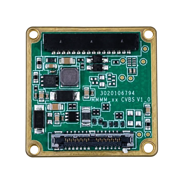
Compact OEM families such as Teledyne FLIR Lepton illustrate why each core must be assessed with its own documentation. Resolution, thermal sensitivity, lens, video output and temperature-measurement support are separate properties. Do not transfer the specification or SDK of one family to another. For an industrial inspection, define the smallest feature to sample and the temperature information actually required before comparing modules.
2. Sensor Resolution, Pixel Pitch, NETD & Aerial Optics Selection
The optical starting point for a thermal camera for drones is the feature size, working distance and viewing angle. Detector resolution and pixel pitch determine the sensor geometry; focal length determines the angular coverage. Thermal sensitivity affects low-contrast imaging, while calibrated temperature accuracy is a separate radiometric specification. A sampling calculation is useful for planning, but it cannot guarantee that an anomaly will be visible or measurable.
Ground Sample Distance (GSD) Calculation
Ground Sample Distance (GSD) is the ground distance represented by one pixel. For a nadir-looking camera over approximately level ground, the small-angle estimate below gives GSD in millimeters per pixel when the stated units are used:
GSD_thermal [mm/pixel] ≈ (Pixel Pitch [μm] × Height Above Ground [m]) / Focal Length [mm]
For a 12 μm detector at 50 m above ground with a 25 mm lens, the estimate is (12 × 50) / 25 = 24 mm/pixel, or 2.4 cm/pixel. At the same height, a 50 mm lens gives (12 × 50) / 50 = 12 mm/pixel, or 1.2 cm/pixel. These are nominal geometric samples; oblique viewing, terrain, blur and lens performance affect the result. The thermal imaging calculator can help explore geometry with explicit assumptions, followed by sample and flight validation.
Sensor Resolution Dynamics: 384×288 vs. 640×512
A 384×288 array contains 110,592 pixels; a 640×512 array contains 327,680. The latter has about 2.96 times the total pixel count, not three times the linear resolving power. These are image pixels, not automatically calibrated temperature points. At the same pitch and focal length, a larger array primarily increases coverage while keeping nominal angular sampling per pixel similar. Compare resolution together with the intended field of view and recording pipeline.
Pixel Pitch Advantages: 12μm Architecture
At a fixed pixel count and focal length, a smaller pixel pitch narrows the field of view and reduces nominal angular sampling per pixel. A shorter focal length can recover comparable coverage, subject to the lens design. That geometry can be useful when selecting a thermal camera for drones, but it does not establish the mass of the complete optical assembly or a flight-endurance improvement. Use the ordered lens and board dimensions when sizing the mount.
Noise Equivalent Temperature Difference (NETD)
NETD describes noise-equivalent temperature difference under stated test conditions; it is not absolute temperature accuracy. Compare NETD only with its temperature, aperture and other published conditions. AeroMini lists ≤30 mK at 25°C and F/1.0. That rating does not mean the non-radiometric version measures temperature. Select the sensitivity needed for the scene and verify contrast with a sample instead of treating a single NETD threshold as proof of diagnostic capability.
Germanium Optics and Aperture Dynamics
An LWIR optical path needs materials and coatings that transmit the camera’s wavelength band. Germanium is one option; it is not the only thermal-optics material. Specify transmission, focal length, aperture, focus and environmental requirements for the selected assembly. Compare these two geometric choices at the same detector size:
- ✅ Wider coverage: A shorter focal length covers more of the scene for the same detector. Check whether the smallest feature still spans enough pixels for the inspection task.
- ✅ Narrower coverage: A longer focal length places more pixels across a distant feature for the same detector, while reducing coverage. Check pointing, stabilization, focus and survey overlap.
3. SWaP-C, Electrical Interfaces, Video Pipelines & Compliance
A thermal camera for drones must fit the electrical, mechanical and data budgets of the complete aircraft. The camera specification is only one input. Budget the host computer, converters, cables, mounting, enclosure and downlink, then verify thermal behavior and recording performance together.
Payload Mass and Battery Endurance Penalties
There is no universal percentage of flight time lost per 100 grams of payload. Aircraft design, battery, propulsion, wind, temperature, maneuvering and power draw all matter. Weigh the complete installed payload and check center of gravity, mount loads and gimbal balance. Compare baseline and payload-equipped flights under controlled conditions with an appropriate reserve; do not use a bare-core weight as the complete payload mass.
Digital and Analog Video Interface Protocols
Match the selected camera board to the host and downlink. Connector shape alone does not establish protocol, voltage, frame format or software support:
- ⚙️ MIPI / DVP: Verify the exact output mode, lanes, electrical levels, clocking and receiver support. A named interface is not proof that a particular host board or driver works with the module.
- ⚙️ USB / Type-C: Type-C describes a connector, not a guaranteed USB version or video mode. Check the selected board, cable, data format and driver. AeroMini’s 16/26-pin references do not apply to its Type-C board.
- ⚙️ Host encoding and networking: If the project needs RTSP, compressed streaming or recorded metadata, define which component provides it and test the full path. Do not assume an OEM camera exports Ethernet or radiometric data.
- ⚙️ CVBS: Match PAL/NTSC output, wiring and the analog receiver. Measure camera-to-display delay; analog output does not make the complete video path instantaneous.
Thermal Dissipation in Enclosed Airframes
Provide a thermal path that suits the selected core and host electronics, while checking the module’s mounting and isolation requirements. Evaluate the enclosed assembly during warm-up and sustained operation, including changes in image uniformity and correction behavior. An exposed OEM board has no implied weatherproof rating. If the application needs environmental sealing, qualify the completed enclosure, optical window, connectors and heat dissipation together.
Aviation Rules and Payload Integration
For U.S. operations under 14 CFR Part 107, the small unmanned aircraft must weigh less than 55 pounds on takeoff, including everything onboard or attached. Night operations have additional requirements, including the applicable pilot knowledge or training requirement and anti-collision lighting visible for at least 3 statute miles. Thermal video does not replace visual-line-of-sight requirements. Check airspace, registration, Remote ID and the rules for the specific operation. Installing a thermal camera does not by itself establish aircraft or operational compliance.
Use the AeroMini 640 product documentation for a standalone LWIR integration, or review VisionCube DT Pro when visible context and onboard processing are part of the design. Both are component paths for civilian inspection and observation. Confirm the complete bill of materials and host integration; neither example should be treated as a finished handheld viewer or a certified aircraft payload.
4. Uncooled LWIR vs. Dual-Light Optical Fusion for Drone Ops
The first architecture decision is whether the thermal camera for drones needs only an LWIR image or also visible-camera context. Standalone LWIR and visible-plus-thermal designs can both support civilian inspection and observation. Choose from the required evidence and installation budget, then verify what the selected configuration actually outputs.
A standalone LWIR core reduces the number of imaging channels to integrate. AeroMini 640 is one example: its non-radiometric version supplies thermal imagery, with a 60 Hz factory default and a 30 Hz factory option. The module’s typical power is listed as <0.5 W at 25°C, but the complete kit and aircraft electronics need a separate power budget. Thermal contrast can be useful without visible light; it is not a guarantee that an obscured or low-contrast feature can be resolved.
Visible-plus-thermal systems add contextual views, but dual-light hardware does not automatically provide spatially registered image fusion. Picture-in-picture places views together; fusion additionally requires defined alignment and processing. VisionCube DT Pro combines dual visible cameras with a thermal camera and supports picture-in-picture according to its supplied brochure. Confirm synchronization, switching, registration and recorded outputs for the exact revision if the inspection requires them.
For inspection documentation, decide whether separate images, picture-in-picture or validated registration best supports the report. Record the relevant operating conditions and confirm that the visible and thermal views represent the intended area. A label readable in a visible frame does not prove that the thermal channel resolves the same feature. Neither the AeroMini non-radiometric example nor the published VisionCube DT Pro specification establishes calibrated temperature measurement.
5. Product Deep Dive: AeroMini 640 Thermal Camera for Drones
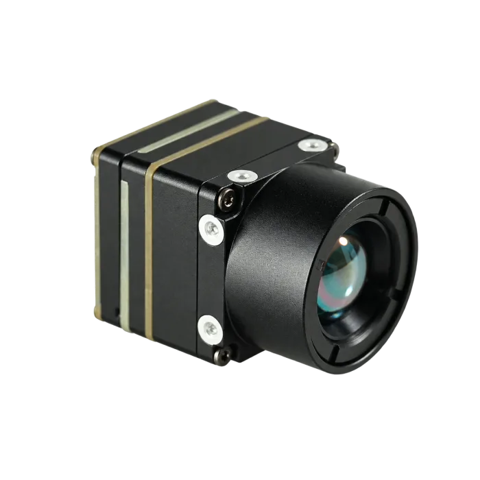
The CAMCUDA AeroMini 640 is a 640×512 uncooled VOx LWIR core for integration. For this thermal camera for drones comparison, the reference is the 9 mm non-radiometric configuration with the USB + CVBS + MIPI tailboard. It is supplied for thermal imaging, without temperature measurement. The photographed assembly below shows the 9 mm module; confirm the board and included cable against the order.
The non-radiometric AeroMini uses a 12 μm pitch and has a 60 Hz factory default, with a 30 Hz factory option at the same price. The current 9 mm lens listing gives 48.7° H × 38.6° V field of view. NETD is ≤30 mK at 25°C, F/1.0. These figures describe the listed configuration; output formats, simultaneous interfaces and delivered frame rates still need confirmation for the selected board and firmware.
The 21 × 21 × 28 mm dimensions and <20 g weight exclude the lens and flange. They are not the complete 9 mm kit envelope or payload mass. AeroMini radiometric is a separate 25 Hz version, currently out of stock and available for supply enquiries, with documented 9/13/18 mm lenses and a −20°C to +550°C measurement range. Confirm accuracy, interface and data format before specifying it for thermography. Do not transfer those properties to the non-radiometric module shown here.
| Technical Parameter | AeroMini 640 · 9 mm Non-radiometric |
|---|---|
| Sensor Type | Uncooled VOx, 8–14 μm |
| Resolution / Pixel Pitch | 640×512 / 12 μm |
| Factory Frame Rate | 60 Hz default; 30 Hz factory option |
| Lens / Published FOV | 9 mm / 48.7° H × 38.6° V |
| NETD (Thermal Sensitivity) | ≤30 mK at 25°C, F/1.0 |
| Mass Reference | <20 g, excluding lens and flange; complete kit to be confirmed |
The USB + CVBS + MIPI kit includes a USB wiring cable and requires customer soldering. Type-C + CVBS is a separate board option; the two boards have different documentation needs. The AeroMini developer FAQ identifies manuals, serial commands and USB-SDK.zip in the AeroMini resource folder. Match those resources to the delivered board, firmware and host. File availability alone does not establish tested Linux compatibility.
6. Product Deep Dive: VisionCube DT Pro Visible + Thermal Module
The CAMCUDA AI VisionCube DT Pro is a component configuration for civilian inspection and observation. It combines dual visible cameras with 6 TOPS processing and a 640×512 thermal camera running at 50 Hz. All VisionCube models list 1920×1080 visible output at 30 Hz. DT Pro is the specific comparison here; S/D omit thermal imaging, while ST/DT use a different 384×288, 25 Hz thermal configuration.
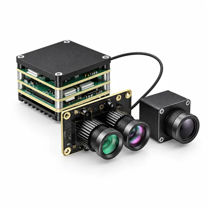
DT Pro lists 3.9 mm wide-angle and 12 mm telephoto visible optics. Their published fields of view are 72° H × 45° V and 26° H × 15° V. Its thermal channel uses 12 μm pitch and 9.1 mm optics with a 45.9° H × 36.9° V field of view. Picture-in-picture support does not establish calibrated fusion, temperature accuracy or identical coverage across channels. Evaluate each output against the planned working distance and viewing conditions.
The common processing-board reference lists a 9–16 V input, 38 × 38 × 29 mm dimensions, 25.5 × 25.5 mm mounting and 43.8 g board weight. These are component specifications. The Pro thermal camera is listed separately as 26 × 26 × 21.1 mm and ≤23 g, excluding lens and connectors. Request the complete DT Pro assembly dimensions, mass, power budget and environmental qualification before designing a flight installation.
| Technical Parameter | VisionCube DT Pro Configuration |
|---|---|
| Visible Cameras | Dual visible: 3.9 mm wide-angle + 12 mm telephoto |
| Visible Output | 1920×1080 at 30 Hz |
| Thermal Resolution / Rate | 640×512 at 50 Hz |
| Thermal Pitch / Optics | 12 μm / 9.1 mm |
| Thermal FOV | 45.9° H × 36.9° V |
| AI Processing | 6 TOPS; application performance requires validation |
| View Mode | Picture-in-picture per supplied brochure; fusion is not established |
| Processing-Board Reference | 9–16 V; 38 × 38 × 29 mm; 43.8 g, not complete kit dimensions or mass |
For the DT Pro dedicated AI interface, request the connector definition, electrical levels, protocol and software documents for the exact supplied revision. AeroMini developer files do not cover VisionCube. The family demonstration video includes supplier annotations and tracking overlays, but does not validate performance for the ordered assembly. Define a civilian acceptance test for usable imagery, recording, picture-in-picture and host communication; do not infer guaranteed tracking, latency or radiometry from the video.
7. Hardware Specifications Matrix & Aerial Benchmark
The comparison below keeps a standalone thermal core and a visible-plus-thermal component configuration distinct. It is a procurement starting point for a thermal camera for drones, not a complete-payload benchmark. Confirm the ordered revision and the excluded parts before using a figure in the mechanical, power or flight budget:
| Technical Parameter | AeroMini 640 · 9 mm Non-radiometric | VisionCube DT Pro |
|---|---|---|
| Direct Product Link | Product Details Page | Product Details Page |
| Imaging Architecture | Standalone uncooled VOx LWIR core | Dual visible cameras + thermal camera + processing board |
| Thermal Spectral Band | 8–14 μm | 8–14 μm |
| Thermal Resolution | 640×512 | 640×512 |
| Thermal Pixel Pitch | 12 μm | 12 μm |
| Frame Rates | Thermal: 60 Hz default / 30 Hz factory option | Thermal: 50 Hz; visible: 30 Hz |
| Optics | 9 mm thermal reference configuration | 9.1 mm thermal; 3.9 mm + 12 mm visible |
| Thermal FOV (H × V) | 48.7° × 38.6° | 45.9° × 36.9° |
| Temperature Measurement | Not supported by this non-radiometric version | Calibrated radiometry not established by the published specification |
| Power Scope | <0.5 W typical module consumption at 25°C; complete kit may differ | 9–16 V processing-board input; complete-system power to be confirmed |
| Integration Scope | Selected USB + CVBS + MIPI board; verify mode, firmware and host | Thermal USB; request DT Pro revision-specific AI interface and host documents |
| Dimensions Reference | 21 × 21 × 28 mm, excluding lens and flange | Thermal camera: 26 × 26 × 21.1 mm, excluding lens and connectors |
| Mass Reference | <20 g, excluding lens and flange | Thermal camera: ≤23 g, excluding lens and connectors; board: 43.8 g; total kit to be confirmed |
8. NDAA Compliance, Export Controls & Drone OEM RFQ Engineering
Before purchasing a thermal camera for drones, identify the country of operation, buyer, end use, destination and any contract-specific sourcing requirements. Record the manufacturer and model for each relevant component. A product description or general supplier declaration cannot by itself establish compliance for an entire aircraft, procurement or international shipment.
For applicable U.S. federal contracts, FAR 52.204-25 addresses covered telecommunications and video-surveillance equipment and services under Section 889. FAR 52.240-1 separately addresses UAS manufactured or assembled by American Security Drone Act covered foreign entities and requires the applicable SAM list review. Scope, exceptions and waivers depend on the rule and contract. Ask for model-specific sourcing evidence and have the procurement team assess the complete system; this guide makes no NDAA-compliance claim for either module.
For U.S. export-control review, determine whether the item is subject to the EAR and establish the applicable classification before assessing destination, end user, end use and licensing requirements. BIS classification guidance is a starting point; an ECCN alone is not a shipment authorization. The related CAMCUDA RFQ documentation guide can help organize supplier questions. Do not assume that an imaging-only label or a supplier’s non-ITAR statement resolves all applicable controls.
Engineering RFQ Checklist for Drone Thermal Integration
- ⚙️ Imaging objective: State whether the thermal camera for drones must provide contrast imagery or calibrated temperatures. Identify the selected model, version, resolution and frame rate.
- ⚙️ Optics and sampling: State the working distance, viewing angle, minimum feature size and coverage. Use GSD as a geometric estimate and validate useful detail with the ordered lens.
- ⚙️ Image and measurement criteria: Record NETD with its test conditions. For radiometry, separately request accuracy, measurement range, calibration and data format.
- ⚙️ Electrical and software interface: Obtain the matched connector, pinout, supply, serial levels, output format and SDK. Confirm firmware and host compatibility with a sample.
- ⚙️ Complete assembly: Request lens-specific dimensions, mounting, total mass, power and enclosure qualification. Include cables, host compute and stabilization hardware in the payload budget.
- ⚙️ Procurement and export review: Request model-specific origin and supply-chain records, applicable classification and destination/end-user documentation. Check the current contract and shipment requirements.

The AeroMini 26-pin MIPI/DVP schematic is a separate reference. Use its 26-pin signal table and datasheet page 4; POWER_IN2 is also 5 V. Do not apply 12 V to either illustrated POWER_IN input. These 16/26-pin diagrams do not apply to Type-C, SuperMini or VisionCube hardware. Request the matched board guide and a mechanical drawing for the ordered AeroMini 9 mm assembly; the public 7 mm STEP resource is not a substitute.
9. Deep-Dive Drone Thermal Payload FAQ
Can I mount a detachable thermal camera core onto a DIY or commercial drone without sacrificing flight time?
A detachable thermal core can be integrated, but no fixed flight-time penalty can be promised. Budget the complete lens, board, cables, converter, host computer, mount and enclosure, then check center of gravity and flight performance. AeroMini’s <20 g figure excludes the lens and flange; its <0.5 W figure is typical module consumption at 25°C, not the complete payload load. For the illustrated AeroMini board, POWER_IN1 and POWER_IN2 are 5 V inputs. Use the matched power documentation and test the installed aircraft with an appropriate battery reserve.
Is a standalone thermal camera sufficient, or should I use a dual-light (thermal + visible) payload for drone inspections?
Use standalone LWIR when the required evidence is thermal contrast and one imaging channel meets the workflow. Add visible imagery when contextual views help identify and document the inspected area. AeroMini non-radiometric is the standalone example here; VisionCube DT Pro adds dual visible cameras and picture-in-picture. Picture-in-picture does not prove spatially registered fusion, and neither example establishes calibrated temperatures. If the task requires quantitative thermography, specify and validate a radiometric configuration, its accuracy and data output separately.
What engineering specs are most critical when selecting an OEM drone thermal module?
Check five areas: (1) Resolution and Pixel Pitch: compare pixel count, coverage and geometric sampling. (2) Thermal Sensitivity: record NETD test conditions separately from temperature accuracy. (3) Frame Rate: verify the output mode, correction interruptions and complete video path. (4) Optics: select focal length, aperture and focus for the task. (5) Data and SWaP: specify imaging or calibrated temperatures, then budget the complete assembly and confirm electrical levels, firmware and host support. The AeroMini FAQ links its own manuals and SDK resources. VisionCube DT Pro requires its exact revision’s AI interface and software documents.
📚 References & Further Reading
- OEM reference: Compare the documentation for AeroMini 640 and VisionCube DT Pro; their hardware and resources are not interchangeable.
- Flight rules: Check 14 CFR Part 107 and the requirements applicable to the aircraft and operation.
- Procurement and export sources: Review FAR 52.204-25, FAR 52.240-1 and BIS classification guidance for the relevant transaction.
- Integration resources: Use the AeroMini datasheet and AeroMini developer folder only for the matching AeroMini configuration. Request separate revision-specific documents for VisionCube.
- Geometry aid: Use the thermal imaging calculator to explore sampling assumptions; validate the completed payload and inspection workflow before deployment.