Heat Sensor Camera Guide: Working Principles, Resolution, and OEM Selection
Heat Sensor Camera Guide: Working Principles, Resolution, and OEM Selection
Modern infrared imaging has broken out of the era of basic handheld industrial thermometry. Today, it is driving high-speed embedded computer vision, autonomous drone navigation, and round-the-clock perimeter security. At the mechanical and electrical core of every heat sensor camera is a straightforward job: translate invisible long-wave thermal emissions into sharp, calibrated spatial datasets. For system architects, electro-optical engineers, and OEM payload designers, integrating a thermal core means wrestling with microbolometer pixel pitch, thermal sensitivity (Noise Equivalent Temperature Difference, or NETD), optics selection via the Johnson criteria, and high-throughput digital interfaces. When SWaP-C (Size, Weight, Power, and Cost) budgets get squeezed tight across robotics, defense, industrial automation, and aerial platforms, picking the right uncooled Vanadium Oxide (VOx) focal plane array with a matching compute pipeline makes or breaks your build.
Look, thermal core engineering requires an honest understanding of detector semiconductor physics, optical throughput (f-number matching), shutterless versus mechanical Non-Uniformity Correction (NUC), and digital streaming latency. In the shop, whether you are cobbling together a dual-spectrum tracking gimbal for an unmanned aerial vehicle (UAV) or bolting down fixed uncooled microbolometers for continuous predictive maintenance, you have to weigh physical detector dynamics against real-time edge AI inferencing loads. This technical guide breaks down the underlying physics of long-wave infrared (LWIR) sensing, evaluates resolution trade-offs from entry-level formats up to high-density 640×512 arrays, walks through optical DRI calculations, and reviews OEM integration protocols for embedded hardware development cycles.
Table of Contents
- 👉 1. Working Principles & Sensor Physics of Heat Sensor Cameras
- 👉 2. Resolution Tiers, IFOV, and Optical DRI Calculations
- 👉 3. Dual-Spectrum Fusion, Low-Latency Video, and Edge AI Architectures
- 👉 4. OEM Product Showcases: High-Performance Cores & AI Platforms
- 👉 5. Comparative Technical Benchmark
- 👉 6. Electrical, Interface, and Thermal Dissipation Integration
- 👉 7. Deep-Dive Technical FAQ
- 👉 8. Engineering Consultation & Next Steps
1. Working Principles & Sensor Physics of Heat Sensor Cameras
A heat sensor camera detects electromagnetic radiation across the Infrared spectrum, specifically targeting the Long-Wave Infrared (LWIR) atmospheric transmission window between 8 µm and 14 µm. Visible-light sensors like CMOS and CCD imagers rely entirely on reflected ambient light between 0.4 µm and 0.7 µm. Thermal sensors work completely differently: they read naturally emitted photonic energy governed by Planck’s Radiation Law, Wien’s Displacement Law, and the Stefan-Boltzmann Law. The total emissive power of a blackbody emitter is defined by integrating spectral radiance across all wavelengths, formalized by the classic Stefan-Boltzmann equation:
W = ε σ T4
In this equation, W is radiant emittance (W/m²), ε is target surface emissivity (ranging from 0.0 for a polished mirror up to 1.0 for a true blackbody), σ is the Stefan-Boltzmann constant (approximately 5.670374 × 10⁻⁸ W/m²·K4), and T is absolute temperature in Kelvin. Here’s the deal: room-temperature objects around 300 K radiate peak thermal flux right at 9.7 µm. That places the LWIR band right in the sweet spot for passive terrestrial sensing, cutting clean through absolute darkness, heavy solar glare, factory smoke, and thin fog.
Microbolometer Material Physics: Vanadium Oxide (VOx) vs. Amorphous Silicon (α-Si)
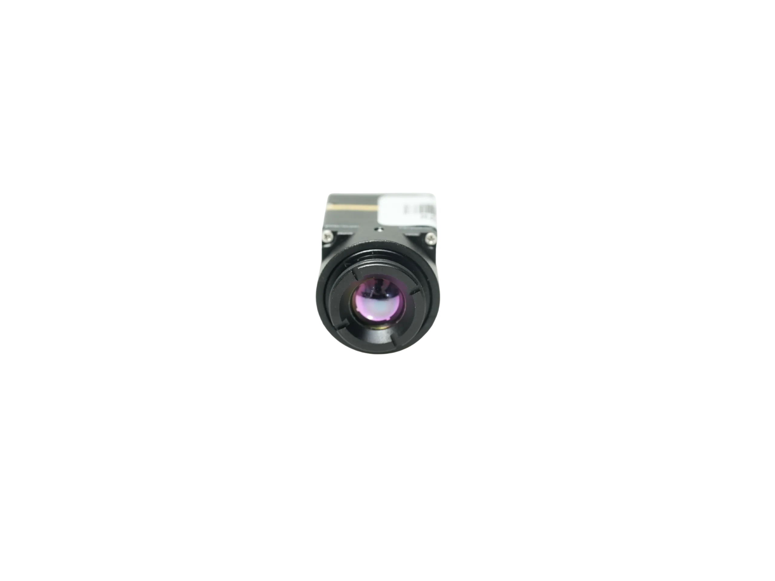
Inside an uncooled thermal core sits the microbolometer Focal Plane Array (FPA). Every individual pixel across the matrix consists of a tiny infrared-absorbing micro-membrane suspended over an underlying silicon Readout Integrated Circuit (ROIC). This membrane sits on micro-machined bridge legs designed with high thermal resistance to maintain vacuum isolation. As incoming LWIR photons hit the membrane, its temperature shifts, changing its internal electrical resistance. How well that transducer behaves comes down directly to material chemistry:
- ⚙️ Vanadium Oxide (VOx): VOx thin films remain the gold standard for high-reliability military, aerospace, and advanced industrial payloads. VOx delivers a high negative Temperature Coefficient of Resistance (TCR), typically running -2% to -3% per Kelvin at room temperature. On top of that, VOx keeps 1/f electrical flicker noise low, allowing the ROIC to pick up minute resistance changes. That translates directly into superior signal-to-noise ratios (SNR) and real-world thermal sensitivity down to ≤30 mK at f/1.0 apertures.
- ⚙️ Amorphous Silicon (α-Si): Amorphous silicon can be deposited directly on standard CMOS semiconductor lines, which keeps raw bill-of-materials costs down. However, α-Si suffers from lower TCR, higher intrinsic 1/f noise, and a larger thermal time constant (τ). That higher time constant slows down transient thermal response and bumps baseline noise floors up to the 40 mK to 50 mK territory.
Noise Equivalent Temperature Difference (NETD) and Optoelectronic Sensitivity
Noise Equivalent Temperature Difference (NETD) is the primary metric for thermal detector sensitivity. Expressed in millikelvins (mK), NETD defines the minimum target temperature difference needed to generate a signal-to-noise ratio of exactly one (SNR = 1) at the ROIC output pins. The theoretical model for microbolometer NETD is expressed as:
NETD = [4 ⋅ F2 ⋅ Vn] / [τo ⋅ Ad ⋅ (dV/dT) ⋅ (ΔP/ΔT)λ1-λ2]
Here, F represents optical system f-number (f/D), Vn is total RMS noise voltage across detector and readout circuits, τo is optical train transmission efficiency, Ad is active pixel area, dV/dT is microbolometer voltage responsivity, and (ΔP/ΔT)λ1-λ2 is the temperature derivative of radiant flux inside the target waveband. A thermal core rated at ≤30 mK easily pulls out faint thermal gradients—like moisture trapped inside composite aircraft wings, fresh tire tracks on tarmac, or human targets obscured by ocean spray—where a ≥50 mK sensor outputs a noisy, washed-out image.
Non-Uniformity Correction (NUC) and Thermal Drift Dynamics
Because microbolometer pixels have tiny manufacturing variations in nominal resistance, thermal mass, and TCR, raw readouts show noticeable spatial Fixed Pattern Noise (FPN). To make matters trickier, temperature changes inside the camera housing alter the internal background radiation bleeding off the lens barrel and internal chassis onto the array. Embedded thermal engines clean this up using two primary methods:
- 📌 1. Mechanical Shutter NUC: A calibrated, high-emissivity mechanical paddle drops in front of the FPA for a split second. The onboard processor grabs a uniform reference frame and recalibrates every pixel’s offset coefficient against a stored calibration table. While dead accurate, that mechanical shutter adds a physical moving part that can wear out, and it freezes the video stream for 200 ms to 500 ms.
- 📌 2. Shutterless Algorithmic NUC: Advanced thermal cores use real-time spatial filtering, motion-based scene statistics, and multi-point thermistor arrays built right onto the sensor board. The onboard processor runs background math to continuously estimate and eliminate sensor drift on the fly without interrupting the feed. That uninterrupted video delivery is non-negotiable for drone flight control, missile guidance, and high-speed robotic vision.
2. Resolution Tiers, IFOV, and Optical DRI Calculations
Choosing your sensor resolution dictates image detail, target classification range, payload weight, power consumption, and downstream computational loads. Entry-level monitoring architectures often get by with compact micro-cores like the TC160-NF 160×120 LWIR Thermal Imaging Module for short-range heat detection and basic presence triggering. However, long-range tactical surveillance and drone tracking demand much higher pixel density.
Stepping up from a 160×120 array (19,200 total pixels) or a 256×192 array (49,152 total pixels) to a 640×512 array (327,680 total pixels) delivers a massive 6.67× jump in active resolving power compared to 256-tier sensors. As detailed in our breakdown on choosing 640×512 thermal camera modules for drone payloads, this added spatial density tightens the Instantaneous Field of View (IFOV). That gives aerial gimbals the ability to scan wide operational areas while keeping enough pixels on distant targets to spot and classify anomalies from safe standoff heights.
Instantaneous Field of View (IFOV) and Optical Calculations
The spatial resolution of an infrared optical assembly is dictated by its Instantaneous Field of View (IFOV), which is the angular footprint covered by a single physical pixel. The math is simple:
IFOV (mrad) = [Pixel Pitch (p in µm) / Focal Length (f in mm)]
Take an uncooled VOx sensor with a 12 µm pixel pitch paired with a standard factory-calibrated 9.1 mm focal length Germanium lens:
IFOV = 12 µm / 9.1 mm = 1.318 mrad
To calculate the physical measurement spot size downrange at target distance (R), multiply IFOV by the range:
Spot Size = Target Distance (R) × IFOV
At a 200-meter standoff distance, that 1.318 mrad optical setup creates a single-pixel spot dimension of 200 m × 0.001318 rad = 0.2636 meters (26.36 cm). To pull an accurate temperature reading without edge blur or point spread distortion, optical engineering best practices require the target to cover at least a 3×3 pixel block (known as Measurement IFOV or MFOV).
Johnson’s Criteria for DRI (Detection, Recognition, Identification)
Surveillance, search-and-rescue, and perimeter defense systems size their optics using the classical Johnson Criteria model. Standardized against target dimensions (1.8 m × 0.5 m with a 0.75 m critical dimension for a human; 2.3 m × 2.3 m with a 1.5 m critical dimension for a vehicle), Johnson’s criteria define the line pairs (or pixel count) needed across the target profile:
- 🔍 Detection (1.5 line pairs / ~3 pixels on target): An operator or neural network can confirm an object is present, distinguishing a warm thermal signature from background clutter.
- 🔍 Recognition (6.0 line pairs / ~12 pixels on target): An observer can identify target classification (e.g., distinguishing a person from an animal, or a pickup truck from a sedan).
- 🔍 Identification (12.0 line pairs / ~24 pixels on target): An observer can distinguish specific target attributes, such as carried gear, vehicle roof racks, or equipment details.
When speccing out lenses for a thermal camera, longer focal lengths like 19 mm or 35 mm narrow your Field of View (HFOV/VFOV), focusing pixel density far downrange for kilometer-range detection. On the flip side, wide-angle lenses like 4.1 mm or 4.9 mm deliver broad situational awareness for close-range robotic navigation and obstacle avoidance.
3. Dual-Spectrum Fusion, Low-Latency Video, and Edge AI Architectures
Modern thermal setups have moved far beyond isolated analog video feeds. High-performance aerospace, security, and robotic systems rely on dual-spectrum payloads that pair visible electro-optical (EO) cameras directly with long-wave infrared (LWIR) cores, linking both to an onboard Neural Processing Unit (NPU) for real-time edge AI tracking.
Multi-Spectral Pixel Fusion Methodologies
Visible CMOS sensors provide high-resolution edge definition, sharp textures, and readable signage in good light, but they become useless in pitch darkness, thick smoke, or heavy camouflage. Thermal cores cut through zero-light conditions and smoke instantly, but they lack surface color and fine mechanical texture. Edge payload processors blend the best of both worlds using real-time spatial fusion engines:
- ⚙️ Picture-in-Picture (PIP): A low-overhead approach where a scaled thermal stream is placed over a visible 1080p canvas (or vice versa), allowing operators to verify thermal hotspots within a broader visual perspective.
- ⚙️ High-Frequency Edge Blending (Spatial Fusion): Real-time 2D Laplacian or Sobel filters isolate sharp edges from the visible sensor. These high-frequency edge vectors are dynamically mapped directly onto the 14-bit thermal image stream, keeping thermal contrast intact while outlining physical edges and fine structural lines.
- ⚙️ Dynamic Range Compression (DRC) & Palette Mapping: Smart histogram equalization and adaptive local contrast algorithms prevent blooming and washout when scorching objects (like engine manifolds or exhaust pipes) appear against freezing backgrounds.
Edge AI Inference and Tracking Engines
Running computer vision models directly at the edge removes the latency bottlenecks of beaming raw video back to a base station. High-throughput machine vision systems frequently build around established standards; for example, high-bandwidth industrial inspection rigs conform to the JIIA CoaXPress Certification Program for multi-gigabit deterministic streaming, while compact embedded robotics rely on low-overhead MIPI CSI-2 and USB UVC pipelines.
Packing dedicated NPU hardware (delivering 4 to 6 TOPS) right at the payload lets embedded platforms run heavy object detection models (such as YOLOv8 or optimized MobileNet backbones) directly across fused dual-spectrum video streams. The tracking engine correlates bounding boxes across both visual and thermal channels simultaneously, keeping a rock-solid target lock even when a target steps from bright sunlight into pitch darkness or ducks behind light brush.
4. OEM Product Showcases: High-Performance Cores & AI Platforms
To help you select the right hardware balance between ultra-compact SWaP-C profiles and edge-AI compute capabilities, let’s examine two field-proven solutions built for professional integration.
TM02-SOLO T Dual-Spectrum UAV AI Tracking Module with 640×512 Thermal Camera
Integrated Dual-Spectrum Tracking Core for Aerial Robotics & Autonomous Payloads
The TM02-SOLO T is an edge-AI tracking platform built specifically for drone OEMs, tactical gimbal builders, and autonomous ground robotics. Pairing a high-definition 1080p visible sensor running at 120 Hz with an uncooled 640×512 VOx LWIR thermal core, the TM02-SOLO T packs a dedicated 6 TOPS NPU and multi-core ARM processor directly onto its 45×45×26 mm compute board. This integrated layout eliminates the need for separate companion computers by handling video ingestion, pixel-level multi-spectral tracking, and flight controller communications directly on the payload board.
Comprehensive Technical Specifications:
| AI Processing, Tracking & Compute | |
|---|---|
| AI Compute Performance | 6 TOPS Edge AI Dedicated NPU Engine |
| CPU Architecture | Arm Cortex-A76 (2.4 GHz) + Cortex-A55 (1.8 GHz) Heterogeneous Core |
| Simultaneous Target Tracks | Up to 120 concurrent tracks (firmware & AI model dependent) |
| Target Classification Types | Person and Vehicle autonomous classification |
| Standoff Reference Tracking | Vehicle: 400 m standoff; Person: 170 m standoff reference |
| Minimum Resolvable Target | 10 × 10 pixels minimum bounding box threshold |
| Dynamic Speed Reference | Up to 450 km/h relative target tracking dynamic velocity |
| Processing Latency | 8 ms supplier core reference (confirm end-to-end flight test setup) |
| Supported Tracking Modes | Reticle locking, close-to-lock, route pre-mapping, lost-target recall, PIP |
| Electro-Optical (Visible) Channel | |
| Optical Sensor Size | 1/1.8-inch high-sensitivity low-light CMOS |
| Visible Resolution & Rate | 1920 × 1080 (1080p) at 120 Hz high-speed acquisition |
| Focal Length & FOV | 8.45 mm focal length | D: 66.3° / H: 57.1° / V: 30.4° |
| Minimum Illumination | 0.001 lux starlight-class low-light performance reference |
| Visible Camera Dimensions | 25.5 × 19.5 × 19.5 mm micro-chassis |
| Thermal (LWIR) Channel | |
| Detector Chemistry | Uncooled Vanadium Oxide (VOx) Focal Plane Array |
| Array Resolution & Pitch | 640 × 512 active pixels | 12 µm pixel pitch |
| Spectral Response Band | 8 µm to 14 µm (LWIR atmospheric window) |
| Thermal Video Output | 50 Hz high-framerate video stream (MIPI interface to processor) |
| Optics & Field of View | 9.1 mm thermal lens | D: 61.8° / H: 47.7° / V: 38.2° |
| Electrical, Control & Mechanical | |
| Input Supply Voltage | Regulated 9 V to 16 V DC direct aircraft supply |
| Telemetry / Control Protocols | CRSF protocol support with native BetaFlight & ArduPilot integration |
| Compute Board Dimensions | 45 × 45 × 26 mm (Mounting pattern: 42.5 × 42.5 mm) |
Integration Note: The TM02-SOLO T thermal channel is dedicated to real-time imaging, PIP overlay, and multi-spectral edge AI tracking. Current documentation does not specify calibrated radiometric thermography; it should not be utilized as an absolute temperature measurement tool without secondary factory qualification.
MD-64CA 640×512 Uncooled VOx Thermal Imaging Camera Module
Ultra-Compact, Low-Power Uncooled Microbolometer Core for Industrial & Robotic Payloads
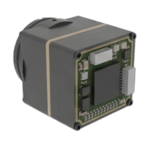
The MD-64CA thermal core packs a high-resolution 640×512 uncooled VOx microbolometer array into an ultra-lightweight 23.1-gram housing, drawing less than 0.7 Watts during continuous operation. Built with a class-leading thermal sensitivity rating of ≤30 mK (NETD at F1.0), the MD-64CA pulls out clean thermal gradient separation even in difficult, low-contrast scenes. Offering versatile output interfaces including CVBS analog composite, USB UVC, and low-latency MIPI CSI-2, the module gives embedded developers a solid plug-and-play block for industrial inspection, robotics, security gimbals, and handheld thermography tools.
Comprehensive Technical Specifications:
| Detector & Optical Parameters | |
|---|---|
| Detector Chemistry | Uncooled Vanadium Oxide (VOx) Focal Plane Array |
| Array Resolution | 640 × 512 active pixels |
| Pixel Pitch | 12 µm micro-machined bolometer structure |
| Spectral Sensitivity | 8 µm to 14 µm (LWIR) |
| Thermal Sensitivity (NETD) | ≤30 mK reference at F1.0 aperture (superior low-contrast resolution) |
| Native Frame Rate | 50 Hz continuous video streaming |
| Optical Aperture Rating | F1.0 high-throughput design |
| Image Pipeline Latency | <20 ms internal processing delay with automatic NUC engine |
| Factory-Installed Lens Options & DRI Estimates | |
| 4.1 mm Focal Length | Ultra-wide-angle option (FOV & IFOV confirmed upon custom quotation) |
| 4.9 mm Lens (In Stock) | FOV: 76.2°×64.2° | IFOV: 2.45 mrad | Human DRI: 476 m (D) / 119 m (R) / 60 m (I) |
| 9.1 mm Lens (Standard Stock) | FOV: 45.8°×37.3° | IFOV: 1.31 mrad | Human DRI: 884.7 m (D) / 221.2 m (R) / 110.6 m (I) |
| 13 mm Lens (Restock/RFQ) | FOV: 33.0°×26.6° | IFOV: 0.92 mrad | Human DRI: 1,263.9 m (D) / 316.0 m (R) / 158.0 m (I) |
| 19 mm Lens (Restock/RFQ) | FOV: 22.9°×18.4° | IFOV: 0.63 mrad | Human DRI: 1,847.2 m (D) / 461.8 m (R) / 230.9 m (I) |
| 35 mm Lens (Restock/RFQ) | FOV: 12.5°×10.0° | IFOV: 0.34 mrad | Human DRI: 3,402.8 m (D) / 850.7 m (R) / 425.4 m (I) |
| Electrical, Video Interface & Environmental | |
| Interface Output Configurations | Selectable at build: CVBS Analog (PAL), USB UVC, or MIPI CSI-2 |
| Power Consumption | <0.7 W ultra-low-power continuous draw |
| Operating Supply Input | 5 V to 24 V DC wide-voltage tolerance |
| Operating Temperature Range | -20 °C to +60 °C industrial operational rating |
| Core Module Weight | 23.1 g bare module (ultra-lightweight SWaP profile) |
Factory Lens Note: MD-64CA lenses are thread-calibrated, focused, and sealed at the factory and are not intended for field replacement. Optical configuration (from 4.1 mm wide angle to 35 mm telephoto) must be frozen prior to volume production orders.
5. Comparative Technical Benchmark
The following engineering benchmark directly compares the technical architectures, optical configurations, computational pipelines, and electrical demands of the standalone MD-64CA thermal imaging module against the dual-spectrum, AI-integrated TM02-SOLO T tracking core.
| System Parameter | MD-64CA Thermal Module | TM02-SOLO T Dual-Spectrum AI Core |
|---|---|---|
| Primary Architecture | Pure LWIR Thermal Imaging Core | Dual-Spectrum (EO + LWIR) + 6 TOPS Edge AI |
| Thermal Resolution & Pitch | 640 × 512 | 12 µm VOx | 640 × 512 | 12 µm VOx |
| Visible (EO) Channel | None (Thermal Dedicated) | 1/1.8″ CMOS | 1080p @ 120 Hz | 8.45 mm lens |
| Thermal Framerate & NETD | 50 Hz | ≤30 mK (at F1.0) | 50 Hz | Standard uncooled VOx profile |
| Optics Selection | Factory Options: 4.1, 4.9, 9.1, 13, 19, 35 mm | Fixed: 9.1 mm LWIR (47.7° HFOV) + 8.45 mm EO |
| Johnson Criteria (9.1 mm Lens) | Human: 884.7 m (D) / 221.2 m (R) / 110.6 m (I) | Tracking Reference: 170 m (Person) / 400 m (Vehicle) |
| Onboard AI Inference | External Host Dependent (Core FPGA Only) | 6 TOPS NPU + Arm A76/A55 | Up to 120 tracks |
| Video & Telemetry Output | CVBS (Analog PAL), USB UVC, or MIPI | MIPI internal, CRSF Telemetry, Flight Autopilot out |
| Input Voltage Range | 5 V to 24 V DC wide range | Regulated 9 V to 16 V DC |
| Power Consumption | <0.7 W continuous | High-performance edge compute profile |
| Form Factor & Mass | 23.1 g (bare module) | Micro payload profile | 45 × 45 × 26 mm compute board + dual camera heads |
6. Electrical, Interface, and Thermal Dissipation Integration
When you sit down to integrate heat sensor cameras into industrial enclosures, airborne 2-axis or 3-axis gimbals, or autonomous mobile robots (AMRs), you have to respect mechanical, electrical, and optical design boundaries.
1. Thermal Dissipation and Grounding Architecture
Uncooled microbolometers are sensitive to ambient temperature gradients moving across the camera housing. If heat conducts unevenly from nearby voltage regulators, switching converters, or edge AI processors into the back of the FPA substrate, you get spatial vignetting, fixed-pattern noise (FPN), and drifting calibration offsets:
- ⚠️ Conduction Heat Paths: The thermal core housing must make direct, clean contact with an external aluminum enclosure or heatsink using high-thermal-conductivity interface gap pads (≥3.0 W/m·K). Never trap an uncooled thermal core inside a sealed, non-conductive plastic box without a defined thermal path.
- ⚠️ Clean DC Power Delivery: Microbolometers demand quiet DC power rails. Switching ripple on your main DC supply must be kept strictly below 30 mVpp using low-dropout (LDO) linear regulators and ferrite filtering. High ripple voltages show up as nasty vertical noise banding across raw thermal video frames.
2. Interface Selection: MIPI vs. USB UVC vs. CVBS
Picking your video interface locks in your hardware architecture and software stack early in the design cycle:
- ⚙️ MIPI CSI-2: The go-to choice for tightly integrated embedded systems (such as NVIDIA Jetson, Rockchip RK3588, or Raspberry Pi Compute Modules). MIPI streams uncompressed, 14-bit raw radiometric data straight into the host processor’s ISP with sub-millisecond transmission latency—a requirement for real-time tracking pipelines.
- ⚙️ USB UVC (Universal Video Class): Delivers driverless plug-and-play operation across Linux and Windows industrial boxes. It is ideal for rapid bench testing, lab test benches, and industrial workstations where pre-processed YUV/RGB video streams get the job done.
- ⚙️ CVBS (Analog Composite): Still holds strong in legacy defense systems, low-latency FPV video links, and analog telemetry setups where digital buffering delays and OS handshake stalls cannot be allowed.
3. Optical Materials and Environmental Protection
Standard optical glass (like BK7 or fused silica) is completely opaque to infrared wavelengths in the 8 µm to 14 µm LWIR band. Thermal optics demand specialized infrared-transmitting materials:
- 📌 Germanium (Ge): Packs a high refractive index (n ≈ 4.0), making it great for building compact, high-resolution optical elements with minimal spherical aberration. However, exposed outer Germanium elements need Diamond-Like Carbon (DLC) or High-Durability Anti-Reflective (HDAR) coatings to shrug off sand abrasion, saltwater spray, and surface scratches.
- 📌 Chalcogenide Glass: An engineered amorphous material containing chalcogen elements (sulfur, selenium, tellurium). Chalcogenide glass can be precision molded rather than diamond turned, which lowers production costs in volume manufacturing. In addition, its low thermal focal drift coefficient (dn/dT) makes it ideal for athermalized lens assemblies that hold focus across broad operating swings (-40 °C to +80 °C).
7. Deep-Dive Technical FAQ
How does an uncooled heat sensor camera measure surface temperature without physical contact?
Why do many entry-level thermal cameras use 256×192 sensors, and when is an upgrade to 640×512 necessary?
What core hardware and electrical constraints must be validated before freezing an OEM thermal module design?
What is the practical engineering difference between radiometric thermal cores and imaging-only thermal modules?
8. Engineering Consultation & Next Steps
Integrating an uncooled thermal core into an industrial automation platform, security gimbal, or unmanned aerial vehicle comes down to matching detector physics to embedded compute constraints. For pinout schematics, lens ray traces, 3D STEP models, and evaluation kits, check out the broader technical library on the Camcuda Vision Engineering Blog or reach out directly to review your project’s payload specifications.
📚 References & Further Reading
- Industry Standard: JIIA CoaXPress Certification Program
- Optical Science Reference: Wikipedia – Infrared Radiation & Detection Physics
- Related Payload Guide: Choosing 640×512 Thermal Modules for Drone Payloads
- Entry-Tier Hardware: TC160-NF 160×120 Microbolometer Core