Building a Drone with Thermal Imaging Camera: OEM Core Selection & SWaP Guide
Building a Drone with Thermal Imaging Camera: OEM Core Selection & SWaP Guide
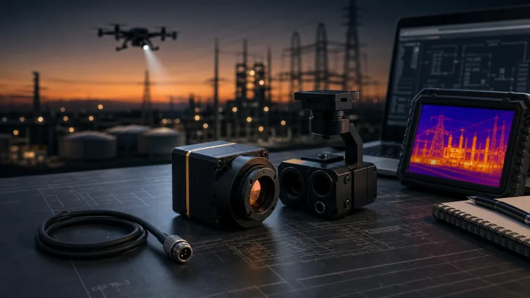
Designing and deploying an airborne long-wave infrared (LWIR) payload comes down to managing brutal mechanical, electrical, and optical trade-offs. Here’s the deal: integrating a drone with thermal imaging camera capability involves far more than slapping an off-the-shelf imager onto a multirotor airframe. If you have spent any time at the test bench, you know that payload systems engineers must wrestle with unforgiving Size, Weight, Power, and Cost (SWaP-C) limitations.
You are tasked with designing sub-millivolt noise-isolated power supplies, routing high-throughput video pipelines like MIPI CSI-2 or parallel BT.656 through miniature slip rings, and calibrating athermalized optics that hold zero across brutal ambient temperature swings. Whether your goal is building a sub-250-gram tactical micro-UAV or an industrial thermography rig for high-voltage utility lines, your choice of the core infrared engine dictates overall payload efficiency, gimbal stabilization accuracy, and host processing overhead.
Look at how the underlying sensor technology has evolved. Modern uncooled Vanadium Oxide (VOx) focal plane arrays (FPAs) have moved aggressively to tighter pixel pitches—transitioning from legacy 17 µm and 12 µm architectures down to ultra-compact 8 µm nodes. This shrink lets us pack crisp 640 × 512 LWIR capability into a fraction of the mass and optical volume required just a few years ago. But shrinking the silicon does not give you a free pass on the physics.
Thermal dissipation, ultra-clean power rail filtering, and frame rate selection—such as weighing high-refresh 50/60 Hz guidance feeds against calibrated 25/30 Hz radiometric telemetry—demand rigorous upfront engineering. This technical guide lays out the practical criteria for selecting OEM thermal camera modules, architecting low-SWaP electrical and mechanical interfaces, and deploying reliable aerial inspection systems that deliver clean data under real flight conditions.
Table of Contents
- 👉 1. SWaP-C Engineering & Mechanical Payload Balancing
- 👉 2. Sensor Physics: 8 µm vs. 12 µm VOx, NETD, and Aerial Optics
- 👉 3. Video Pipelines: Qualitative Imaging vs. Calibrated Radiometry
- 👉 4. Power Distribution, Rail Ripple Mitigation & Digital Bus Integration
- 👉 5. Real-World OEM Module Showcase & Technical Specifications
- 👉 6. Step-by-Step Electrical, Thermal & Mechanical Integration Workflow
- 👉 7. Deep-Dive Engineering FAQ
1. SWaP-C Engineering & Mechanical Payload Balancing
In the drone world, every single gram added to the payload eats into battery discharge curves and robs you of hover endurance. When building an integrated drone with thermal imaging camera payload, mechanical packaging dictates gimbal motor sizing, structural resonance dampening, and your overall aerodynamic profile. Modern airborne systems mount the thermal engine into a stabilized pan-tilt assembly tied directly to the main avionics bay, routing high-speed MIPI CSI-2, parallel digital video, or USB streams straight into edge companion compute modules alongside telemetry lines.
Micro-gimbals driven by 2-axis or 3-axis brushless DC (BLDC) motors depend on near-perfect Center of Gravity (CoG) alignment. Hang an awkwardly balanced thermal core out on the pitch arm, and the gimbal motors are forced to pull continuous holding current just to maintain level horizon. In the shop, we see this all the time: that parasitic current draw leads directly to motor overheating, high-frequency mechanical jitter, and rolling shutter wobble across co-mounted daylight visual sensors. When budgeting your mechanical layout, thermal cores generally fall into two distinct mass classes:
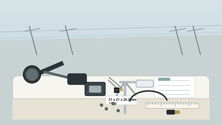
- ⚙️ Sub-3.5 g Cores (8 µm Class): Ultra-miniature cores with a bare-core envelope around 13 × 13 × 13.4 mm, excluding optics and expansion boards, completely shift the design equation. Motor sizing and complete payload mass still depend on the selected optics, expansion board, cables, slip rings and gimbal structure; validate the assembled mass and balance against the airframe budget.
- ⚙️ Sub-20 g Cores (12 µm Class): Standard 21 × 21 × 28 mm OEM modules (dimensions and sub-20 g weight exclude lens and flange) represent a bulletproof mid-tier baseline. Check the complete lens and interface-board assembly against the selected electro-optical/infrared (EO/IR) dual-sensor gimbal envelope. Size mounting brackets and gimbal motors from the complete assembly mass, center of gravity and tested flight loads; the core specification does not establish a wind-stabilization rating.
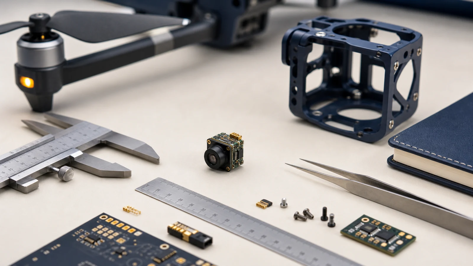
For detailed engineering considerations on structural integration and multi-sensor stabilization, refer to our comprehensive engineering guide to thermal payloads and OEM integration.
Uncooled VOx microbolometers skip the heavy, power-hungry cryogenic Stirling coolers found on cooled MWIR rigs, but their detector sensitivity depends entirely on thermal stability across the core housing. Internal FPA self-heating changes detector substrate temperatures continuously. If that heat builds up unevenly, your system will trigger constant Non-Uniformity Correction (NUC) shutter cycles, freezing video feeds right when the pilot or autonomous tracking engine needs them most.
To keep thermal drift under control, mount the core chassis directly to an aluminum (6061-T6) or magnesium alloy gimbal yoke using thermal interface materials (TIM) rated at a minimum of 3.0 W/m·K. Route your enclosure airflow to take advantage of prop downwash for heat extraction, but shield the front optics so turbulent pressure differentials do not cool the athermal lens barrel unevenly. Keep high-heat culprits—like companion AI processors, video encoding SoCs, and switching regulators—isolated from the LWIR sensor housing.
2. Sensor Physics: 8 µm vs. 12 µm VOx, NETD, and Aerial Optics
Selecting the right detector engine comes down to the core optical math: Instantaneous Field of View (IFOV), Ground Sampling Distance (GSD), and optical aperture mass. The underlying sensor physics dictates the mechanical profile of the drone’s optical payload.
For over a decade, 17 µm and 12 µm were the default pixel pitch standards for uncooled long-wave infrared (8–14 µm) sensors. The move to 8 µm VOx pixel pitch architectures provides massive optical advantages for airborne platforms. To hit a specific Field of View (FOV), an 8 µm sensor requires a substantially shorter focal length than a 12 µm detector. For instance, an 8.7 mm lens on an 8 µm 640 × 512 core yields a balanced 40.0° × 32.2° FOV. Achieving that identical field on a 12 µm sensor requires roughly a 13 mm focal length.
Germanium (Ge) and Chalcogenide infrared optical elements are dense and heavy. Shorter focal length lenses use smaller clear apertures while holding fast F1.0 light-gathering performance, slashing front-element glass mass by up to 60%. Removing that front-heavy mass lowers the rotational moment of inertia on your gimbal axes, reducing motor strain and eliminating stabilization overshoot.
The spatial resolution on the ground is defined by the sensor’s IFOV, calculated through fundamental optical principles:
IFOV = p / f | GSDH = H × IFOV = H × (p / f)
Where p represents the pixel pitch, f is the focal length of the optical assembly, and H is your flight altitude above ground level (AGL). Use the thermal imaging calculator with your actual pixel pitch, focal length and target distance to check optical geometry; it does not guarantee detection performance or temperature accuracy. The optical engineering matrix below compares standard configurations across standard flight profiles:
| Configuration | Pixel Pitch | Focal Length | IFOV | FOV (H × V) | GSD at 50 m AGL | GSD at 100 m AGL |
|---|---|---|---|---|---|---|
| SuperMini 640 | 8 µm | 3.7 mm | 2.16 mrad | 90.0° × 68.2° | 10.8 cm/px | 21.6 cm/px |
| SuperMini 640 | 8 µm | 6.1 mm | 1.31 mrad | 46.6° × 37.6° | 6.55 cm/px | 13.1 cm/px |
| SuperMini 640 | 8 µm | 8.7 mm | 0.92 mrad | 40.0° × 32.2° | 4.60 cm/px | 9.20 cm/px |
| SuperMini 640 | 8 µm | 11.0 mm | 0.73 mrad | 24.9° × 20.0° | 3.65 cm/px | 7.30 cm/px |
| AeroMini 640 | 12 µm | 9.0 mm | 1.33 mrad | 48.7° × 38.6° | 6.65 cm/px | 13.3 cm/px |
| AeroMini 640 | 12 µm | 13.0 mm | 0.92 mrad | 31.9° × 25.7° | 4.60 cm/px | 9.20 cm/px |
| AeroMini 640 | 12 µm | 25.0 mm | 0.48 mrad | 17.5° × 14.0° | 2.40 cm/px | 4.80 cm/px |
Noise Equivalent Temperature Difference (NETD) defines the smallest thermal delta the sensor can pull out of the electronic noise floor. An NETD rating of ≤30 mK provides extraordinary sensitivity, which is critical when flying over low-thermal-contrast scenes like open water Search and Rescue (SAR), maritime patrol, or overcast night operations. An NETD rating of ≤40 mK delivers an ideal blend of sensitivity and thermal core compactness for structural surveys, high-voltage line inspections, and fast-moving FPV tactical feeds.
To evaluate broader payload selection criteria across different operational altitudes, check out our guide on choosing OEM cores for aerial thermal payloads.
3. Video Pipelines: Qualitative Imaging vs. Calibrated Radiometry
Before you commit to a specific OEM core, lock down your operational requirement: do you need qualitative thermal imaging or calibrated thermography (radiometry)? The underlying architecture, data throughput, and onboard processor loading look completely different depending on which path you take.
Qualitative imaging serves tactical ISR, pilot situational awareness, perimeter security, and search missions. The image processing pipeline relies on aggressive dynamic range compression algorithms, including Digital Detail Enhancement (DDE) and Adaptive Gain Control (AGC). These algorithms compress raw 14-bit microbolometer data into punchy, high-contrast 8-bit streams using White Hot, Black Hot, or false-color palettes like Ironbow. Qualitative pipelines prioritize high frame rates—running at 50 Hz or 60 Hz—to keep display latency low for responsive manual piloting and high-speed obstacle avoidance. After a compatible video-capture path is confirmed, host applications may use the Khronos OpenVX API for computer-vision processing.
Radiometric thermal imaging is mandatory for utility substations, solar farm string audits, industrial flare stack monitoring, and agricultural moisture mapping. A radiometric engine provides temperature data in a model-specific format; the SuperMini 640T specifies ranges of −20°C to +150°C and +100°C to +650°C. For SuperMini 640T, CDS3 carries image and temperature data; MIPI uses RAW8 packets that the host assembles into 16-bit image and TEMP words, low byte first. AeroMini radiometric output and interface require separate confirmation; the standard AeroMini configuration does not provide RAW or minimally processed output. The SuperMini 640T operates at 30 Hz. AeroMini radiometric is a separate 25 Hz version, currently out of stock with availability by enquiry only.
For broader industrial monitoring context, Dahua Technology is an external vendor example; interoperability with CAMCUDA hardware requires project-specific verification.
For more details on bridging qualitative situational feeds with radiometric analysis, take a look at our deep dive on infrared drone camera design and thermal payload engineering.
4. Power Distribution, Rail Ripple Mitigation & Digital Bus Integration
Clean power is non-negotiable when dealing with high-performance LWIR microbolometers. Uncooled VOx FPAs are sensitive analog-to-digital sensor systems. High-frequency noise or switching transients on your DC rails show up immediately as horizontal banding, scrolling fixed-pattern bars, or degraded NETD performance right in your video downlink.
When laying out custom carrier boards for aerial thermal systems, choose the supply architecture to meet the selected core and interface board’s voltage, noise, current and startup requirements. The SuperMini bare core requires MAIN_POWER at 3.8–5.2 V (nominal 5.0 V), plus 3.28–3.32 V and 1.78–1.82 V rails. The MAIN_POWER and 3.3 V rails allow at most 10 mV p-p noise; the 1.8 V rail allows at most 1 mV RMS over 1 Hz–50 kHz. Follow the SuperMini manual’s power-on timing.
Check how switching noise from flight motors and Electronic Speed Controllers (ESCs) affects the sensor rails under operating loads. Select the regulators and voltage headroom against the actual battery range, required rails, peak currents, noise limits and power-on sequence; confirm the design against the matched integration guidance. Confirm decoupling values, placement and regulator-stability requirements for the selected carrier design.
When selecting your digital interface, weigh the strengths of each protocol:
- ✅ 2-Lane MIPI CSI-2: Carries video to a compatible receiver; validate the module’s format, receiver and driver support against the selected host platform and matching SDK. Set differential-pair impedance, length matching and routing limits from the core and host interface requirements. Validate the complete video path, including any cables or gimbal slip rings, on the selected hardware.
- ✅ 8-Bit LVCMOS / BT.656: Delivers deterministic parallel clock timing with broad hardware compatibility across embedded video encoders and wireless transmitters. Make sure all 8 data lines, pixel clock (PCLK), and sync lines (HSYNC, VSYNC) are matched in trace length across your carrier PCB.
- ✅ USB 2.0 / UVC (Universal Video Class): USB capture depends on the selected module, interface board, firmware and host software. Use the matching AeroMini driver and SDK resources for AeroMini or the SuperMini documentation for SuperMini, and validate the requested format and rate before relying on a Linux/ROS video pipeline.
5. Real-World OEM Module Showcase & Technical Specifications
Selecting the right OEM thermal imaging module comes down to your airframe’s payload mass budget, target optical resolution, and radiometry requirements. Here is a breakdown of two high-performance OEM LWIR cores built specifically for UAV and robotics integration.
CAMCUDA SuperMini 640 / 640T Ultra-Light LWIR Thermal Camera Module
The CAMCUDA SuperMini 640 / 640T series sets the standard for ultra-low SWaP thermal imaging. Built on an advanced 8 µm pixel pitch uncooled VOx detector with full 640 × 512 resolution, this miniature powerhouse has a bare-core weight below 3.5 grams and dimensions of 13 × 13 × 13.4 mm, excluding optics and expansion boards. It is engineered from the ground up for sub-250g nano-UAVs, micro-gimbals, and tactical FPV platforms where every milligram counts.
The series has two distinct models: the SuperMini 640 (50 Hz qualitative imaging core supporting 8-bit LVCMOS/BT.656 and 2-lane MIPI for low-latency piloting; BT.656 and MIPI cannot operate simultaneously) and the SuperMini 640T (30 Hz radiometric core supporting CDS3 and MIPI temperature streams across dual measurement ranges of −20°C to +150°C and 100°C to +650°C). Optical choices include factory-aligned F1.0 athermalized lenses ranging from 3.7 mm (90.0° × 68.2° FOV) down to 11 mm (24.9° × 20.0° FOV).
| Key Parameter | Technical Specification |
|---|---|
| Resolution & Detector | 640 × 512 Uncooled VOx Focal Plane Array |
| Pixel Pitch & Spectral Range | 8 µm | 8–14 µm (LWIR) |
| Core SWaP Metrics | 13 × 13 × 13.4 mm and <3.5 g, excluding optics and expansion boards | ≤0.5 W typical core power at 25°C, excluding expansion board |
| Thermal Sensitivity (NETD) | ≤40 mK @ 25°C, F1.0 |
| Frame Rates | 640 (Imaging): 50 Hz | 640T (Thermographic): 30 Hz |
| Temperature Measurement (640T) | −20°C to +150°C and 100°C to +650°C |
| Lenses (F1.0 Athermal) | 3.7 mm (90.0°×68.2°), 6.1 mm (46.6°×37.6°), 8.7 mm (40.0°×32.2°), 11 mm (24.9°×20.0°) |
| Electrical Interface | Hirose DF40C-30DP-0.4V(51) 30-pin core connector; MAIN_POWER 3.8–5.2 V plus 3.28–3.32 V and 1.78–1.82 V rails; UART 1.8 V (core-referenced TX/RX) |
CAMCUDA AeroMini 640×512 Uncooled LWIR USB Thermal Camera Core
The CAMCUDA AeroMini 640 is tailored for industrial drone gimbals, multi-rotor inspection platforms, and dual-sensor EO/IR payloads. It couples a 640 × 512 uncooled VOx microbolometer with a 12 µm pixel pitch and an ultra-sensitive NETD of ≤30 mK at 25°C, F/1.0. This sensitivity lets you resolve subtle thermal variations on concrete structures, power line splices, and composite airframes.
The AeroMini 640 family lists YUV, USB, BT.656, and analog CVBS (PAL/NTSC), with UART, RS232, and RS422 control options; availability depends on the selected board and firmware. Use the AeroMini board and PIN reference PDF for the illustrated 16-pin and 26-pin boards; request the matched guide for Type-C.
Weight below 20 grams and dimensions of 21 × 21 × 28 mm exclude lens and flange. Current online non-radiometric lens choices span 4–50 mm; 15, 60 and 75 mm lenses require enquiry. Non-radiometric imaging uses 60 Hz by default or an optional 30 Hz factory configuration. The separate 25 Hz radiometric version (−20°C to +550°C) is currently out of stock and enquiry only; online purchase, pre-order and deposits are unavailable.
| Key Parameter | Technical Specification |
|---|---|
| Resolution & Detector | 640 × 512 Uncooled VOx Focal Plane Array |
| Pixel Pitch & Spectral Range | 12 µm | 8–14 µm (LWIR) |
| Thermal Sensitivity (NETD) | ≤30 mK @ 25°C, F/1.0 |
| Core SWaP Metrics | 21 × 21 × 28 mm and <20 g, both without lens/flange | <0.5 W typical module power at 25°C; complete-kit consumption may differ |
| Frame Rates | Non-radiometric: 60 Hz default / 30 Hz factory option | Radiometric: 25 Hz, enquiry only |
| Temperature Measurement (Radiometric) | −20°C to +550°C (radiometric 9, 13 or 18 mm; enquiry only; accuracy, output format and interface require confirmation) |
| Lens Portfolio | Online non-radiometric: 4 mm (100°×82°), 7, 9, 13, 18, 25, 35 and 50 mm; 15, 60 and 75 mm by enquiry |
| Video & Serial Interfaces | YUV, USB, BT.656, CVBS (PAL/NTSC); UART, RS232, RS422: board/firmware dependent. Use the approved board input; illustrated POWER_IN1/POWER_IN2 are 5 V, never 12 V. |
| Environmental Rating | Operating: −40°C to +80°C | Storage: −50°C to +85°C |
6. Step-by-Step Electrical, Thermal & Mechanical Integration Workflow
Bringing an OEM thermal core into an aerial airframe requires a disciplined engineering sequence across four distinct project phases:
Phase 1: Optical Geometry and FOV Finalization
Lock down your target flight altitude (e.g., 50 m AGL) and required spatial resolution (GSD). Match the detector pitch (8 µm on SuperMini vs. 12 µm on AeroMini) to your required field of view. For broad situational awareness and flight guidance, pick wide optics like the 3.7 mm lens (90.0° FOV). For high-altitude asset surveys, step up to telephoto glass like the 11 mm or 25 mm. Always ensure the optical assembly is factory-aligned and athermalized so your image does not defocus when climbing from ground level to altitude.
Phase 2: Mechanical Integration & Thermal Relief
Design the custom mounting bracket from the approved drawing for the selected lens and interface-board assembly, and confirm material, mating surfaces and tolerances before machining. Confirm the thermal interface material (TIM), contact area and permitted thickness for the selected core housing and gimbal yoke. Calculate the combined center of gravity (CoG) of the core, lens assembly, and flex cabling, positioning the pitch and roll pivot axes to reduce steady-state motor holding current; validate the allowable offset and balance with the gimbal designer.
Phase 3: Carrier PCB Design & Electrical Interface
For the SuperMini module, select the matching host-side connector for the core’s Hirose DF40C-30DP-0.4V(51) 30-pin connector and verify orientation against the SuperMini manual’s connector and PIN table. Supply MAIN_POWER within its specified voltage, current and noise limits. Validate that the +3.3 V rail holds between 3.28 V and 3.32 V with ≤10 mV p-p noise, and verify that the +1.8 V rail sits between 1.78 V and 1.82 V with ≤1 mV RMS noise (1 Hz to 50 kHz).
Route MIPI CSI-2 differential pairs over continuous reference ground planes with tightly matched trace lengths, and select level translation for the 1.8 V core UART and the host’s logic voltage, baud rate, loading and signal direction. UART TX/RX are defined from the core; verify the matched wiring before connection.
Phase 4: Software Ingestion & Radiometric Parsing
Validate video capture on the selected companion computer and use Video4Linux2 (V4L2) or GStreamer where supported. For SuperMini 640T, decode the documented CDS3 or MIPI image/TEMP layout; MIPI uses RAW8 transport with low-byte-first 16-bit words. Apply the SuperMini 640T V1.0.0 manual, Appendix 2 conversion for the actual ND or HD mode:
SuperMini 640T only: ND: T = (TEMP + 7000) / 30 − 273.2
HD: T = (TEMP − 4600) / 10 − 273.2
Here T is in °C; use the confirmed mode and calibration limits for spot-metering or hot-spot alerts. These formulas do not apply to imaging-only SuperMini 640 or AeroMini. AeroMini radiometric output requires confirmation, and standard AeroMini RAW or minimally processed output requires a separate customization assessment. Configure NUC/FFC triggering through commands and conditions documented for the supplied model, and verify any image interruption during the intended operation.
7. Deep-Dive Engineering FAQ
Can I integrate a thermal camera onto a custom drone or micro-gimbal without exceeding SWaP limits?
What is the difference between standard thermal imaging and radiometric thermal cameras for drones?
How do OEM thermal camera modules interface with UAV flight controllers and companion boards?
Technical author: Daniel · Hardware Support
Sales contributors: Vivian, Lena and Sophie
📚 References & Further Reading
- Industry Standard: Computer Vision Acceleration on Embedded Drone Payloads: Khronos OpenVX
- External Vendor Example: Industrial Security and Multispectral Systems: Dahua Technology
- Related Guide: Engineering Guide to Thermal Payloads and OEM Integration
- Related Guide: Infrared Drone Camera Design & Thermal Payload Engineering
- Related Guide: Choosing OEM Thermal Cores for Aerial UAV Integration