IR Camera for Drones: OEM Guide to Low-SWaP 640 LWIR Thermal Payloads
IR Camera for Drones: OEM Guide to Low-SWaP 640 LWIR Thermal Payloads
Technical author: Daniel · Hardware Support and Sales contributors: Vivian, Lena and Sophie.
Modern unmanned aerial system (UAS) engineering operates under unforgiving physical constraints. When you integrate an uncooled long-wave infrared (LWIR) imaging payload onto a micro-gimbal or compact industrial drone, you enter a relentless balancing act between competing physical vectors: sensor spatial resolution, optical aperture volume, thermal dissipation limits, and razor-thin Size, Weight, and Power (SWaP) budgets. Added payload mass and electrical load reduce the remaining flight and thermal budgets. Their effect on endurance, motor temperature and line-of-sight stability depends on the complete aircraft, gimbal, optics and control-loop design, so measure these effects on the assembled payload.
Deploying mission-grade 640×512 thermal imaging at the tactical edge means payload architects must move far beyond chunky, consumer-grade packaging. You need to master bare-core integration mechanics from the bare silicon up. Whether you are building an FPV tactical reconnaissance platform, an automated industrial inspection multirotor, or an AI-enabled perimeter patrol quad, real-world success comes down to exact optical matching, digital bus protocol selection (MIPI CSI-2 vs. BT.656 vs. CVBS), power-rail noise suppression, and knowing when to use a fast situational awareness core versus a pixel-by-pixel radiometric measurement engine.
Table of Contents
- 👉 1. The Physics of Low-SWaP Thermal Integration in Unmanned Systems
- 👉 2. Optical Architecture: Athermalized Fixed-Focus vs. Micro-Optics
- 👉 3. Radiometric vs. Situational Awareness: Selecting the Processing Pipeline
- 👉 4. High-Throughput Digital Bus Integration & Electrical Interfaces
- 👉 5. OEM Technical Reference: 640 LWIR Thermal Cores for Micro-Gimbals
- 👉 6. Mechanical Envelope, Thermal Heat Paths & Gimbal Dynamics
- 👉 7. Frequently Asked Questions (FAQ)
1. The Physics of Low-SWaP Thermal Integration in Unmanned Systems
Here’s the deal: designing an ir camera for drones requires navigating a physical trade-off between pixel pitch, optical volume, and detector thermal stability. For a fixed detector format, pixel pitch sets the active image dimensions; the complete lens envelope also depends on focal length, F-number, optical design and mounting. A 640×512 FPA at 12 μm pitch has an active area of 7.68 × 6.144 mm and a diagonal of approximately 9.84 mm. Achieving a chosen IFOV and image quality requires a matched lens; neither a 30–60 g lens mass nor a particular aperture is a universal consequence of 12 μm pitch.
With sub-10 μm architectures—such as the 8 μm VOx detector in CAMCUDA SuperMini—the active image area is smaller for the same pixel count. An 8 μm 640×512 detector has a 5.12 × 4.096 mm active area and an approximately 6.56 mm diagonal. At the same nominal IFOV, focal length scales with pitch, which can help reduce optical size. Actual lens volume and mass depend on the optical design; the SuperMini specification of less than 3.5 g applies to its bare core, excluding optics and expansion boards.
For broader unmanned-aircraft industry coverage, see sUAS News. In a micro-UAS payload, keeping the combined lens, core, board and harness center of gravity close to the gimbal rotation axes can reduce balancing demands. Motor temperature, vibration and pointing stability still require validation on the complete assembly.
For a point mass, rotational inertia about an axis is I = mr2, where r is the perpendicular distance from that axis. A real payload requires the inertia of its distributed lens, core, boards and harness to be considered. Reducing mass or its offset can reduce actuator demands, but smaller detector pitch alone does not establish cooler motors, faster settling or jitter-free video.
The table separates calculated 640×512 detector geometry from current model-specific specifications. Pixel pitch alone does not determine core mass, lens mass, electrical power or gimbal motor sizing. Compare complete assemblies when setting the flight and stabilization budgets.
| Engineering Vector | 17 μm Reference Geometry | AeroMini 640 · 12 μm | SuperMini 640 / 640T · 8 μm |
|---|---|---|---|
| 640 × 512 Sensor Diagonal | ~13.93 mm | ~9.84 mm | ~6.56 mm |
| Mass Reference (see exclusions) | Model-specific; verify the selected core | <20 g; excludes lens and flange | <3.5 g; excludes optics and expansion boards |
| Wide-Angle Lens Mass | Lens-specific; request assembly mass | Lens-specific; request assembly mass | Lens-specific; request assembly mass |
| Typical Power Consumption | Model-specific; verify the selected core | <0.5 W at 25°C; complete-kit consumption may differ | ≤0.5 W at 25°C; excludes expansion board |
| Gimbal Inertial Load | Calculate for the selected assembly | Calculate for the selected lens, core, boards and harness | Calculate for the selected lens, core, boards and harness |
2. Optical Architecture: Athermalized Fixed-Focus vs. Micro-Optics
Drone payloads encounter altitude changes and ambient temperature swings. Match the optical assembly and enclosure to the specified operating range: AeroMini lists −40°C to +80°C, while SuperMini lists −40°C to +70°C, with −20°C to +60°C for 640T thermography. Temperature-dependent optical properties and mechanical expansion can shift focus and reduce Modulation Transfer Function (MTF); see Edmund Optics’ germanium material reference for material background.
To reduce the bulk and mechanical complexity of motorized focusing, OEM payload designers may use athermalized fixed-focus optical assemblies. Optical materials and mechanical barrel expansion are selected together to limit focus shift over a defined temperature range. The actual athermal performance, MTF and operating limits must be verified for the chosen lens and housing; material names alone do not establish that focus stays fixed across every flight condition.
When selecting optics for tactical mapping, search and rescue (SAR), or infrastructure inspection, review our high-resolution thermal imaging camera OEM selection guide to match target DRI (Detection, Recognition, Identification) metrics to the correct Instantaneous Field of View (IFOV).
IFOV Calculation: IFOV (mrad) = [Pixel Pitch (μm) / Focal Length f’ (mm)]
The following FOV values are the published SuperMini F1.0 athermal-lens specifications; IFOV values follow pitch divided by focal length. Application examples are design starting points and do not establish validated obstacle avoidance, detection range or autonomous navigation performance.
- ⚙️ 3.7 mm Lens (8 μm pitch): IFOV = 2.16 mrad, 90.0° × 68.2° FOV — Wide-field option for proximity imaging, pilot situational awareness, and indoor FPV evaluation.
- ⚙️ 6.1 mm Lens (8 μm pitch): IFOV = 1.31 mrad, 46.6° × 37.6° FOV — Wide-field option for agricultural mapping, search grid patterns, and general perimeter observation.
- ⚙️ 8.7 mm Lens (8 μm pitch): IFOV = 0.92 mrad, 40.0° × 32.2° FOV — Balanced geometry for SAR target spotting and medium-standoff utility line patrols.
- ⚙️ 11.0 mm Lens (8 μm pitch): IFOV = 0.73 mrad, 24.9° × 20.0° FOV — Narrow-field optical tracking for high-altitude scouting and standoff tactical reconnaissance.
3. Radiometric vs. Situational Awareness: Selecting the Processing Pipeline
Look at your mission profile before committing to an architecture: do you need qualitative imaging (situational awareness) or quantitative thermography (radiometry)? This core decision dictates your signal processing pipeline, onboard compute payload, bus bandwidth, and output refresh rates.
Non-Radiometric / Situational Awareness Engines
Non-radiometric cores provide thermal imagery for visual interpretation rather than calibrated temperature measurement. CAMCUDA SuperMini 640 is an imaging-only 50 Hz model; AeroMini non-radiometric imaging is supplied at 60 Hz by default or 30 Hz as a factory option. Image enhancement and output formatting depend on the selected model, firmware and interface. The standard AeroMini configuration is not a RAW or minimally processed output option, and neither a universal 14-bit source format nor a fixed end-to-end latency should be assumed. Potential imaging applications include:
- ✅ Low-latency tactical FPV piloting and agile counter-UAS tracking
- ✅ High-speed night navigation and real-time obstacle detection
- ✅ Search and rescue (SAR) rapid human target isolation
- ✅ Perimeter intrusion detection and wildlife monitoring
Radiometric / Thermographic Engines
Radiometric cores provide calibrated temperature data under model-specific measurement conditions. CAMCUDA SuperMini 640T is the 30 Hz thermographic model; its CDS3 path carries image and temperature data, and its MIPI path transports RAW8 packets that the host reassembles into 16-bit image and temperature words. AeroMini radiometric is a separate 25 Hz version, currently out of stock and available for supply enquiries with documented 9, 13 or 18 mm lenses; its accuracy and RAW data format require confirmation. Quantitative inspection requires suitable calibration, target fill, emissivity and environmental corrections; imaging alone can still reveal qualitative heat patterns. Example measurement workflows include:
- ⚙️ Utility-scale solar farm inspection (detecting cell hotspots and bypassed diodes)
- ⚙️ High-voltage electrical substation maintenance and phase load diagnostics
- ⚙️ Industrial asset profiling, tank level verification, and building envelope diagnostics
- ⚙️ Precision agriculture crop water stress index (CWSI) and canopy transpiration analysis
4. High-Throughput Digital Bus Integration & Electrical Interfaces
Routing thermal video into an aerial edge-compute setup requires matching the electrical interface to your processing demands. Modern airframes split video handling into two main paths: low-latency direct analog feeds for manual control, and wide-bandwidth embedded digital links for edge-AI processing.
Embedded Digital Video Interfaces
2-Lane MIPI CSI-2: A camera transport for compatible embedded receivers. Confirm the exact core, board, lane configuration, voltage levels, data type, frame layout, firmware and host driver before choosing a Jetson, Raspberry Pi or Rockchip platform. DMA and buffer handling depend on the host pipeline; a MIPI connector alone does not establish direct compatibility, zero CPU overhead or a latency guarantee.
8-bit LVCMOS / BT.656: These digital paths require a receiver matched to the selected model’s electrical levels, clocks, synchronization and frame format. SuperMini 640 documents BT656 for imaging; 640T documents CDS3 for image and temperature data. Follow the relevant manual rather than treating these formats as interchangeable.
USB 2.0 / UVC: A matched interface board can simplify host evaluation. AeroMini offers USB-capable configurations and model-specific developer resources; confirm the board, output mode and supported operating system before integration. USB and MIPI latency must be measured in the actual capture and processing pipelines.
For protocol background, refer to the MIPI Alliance CSI-2 overview. The standard describes transport capabilities; it does not certify a CAMCUDA core, carrier board or host implementation.
Low-Latency Analog Transmission
CVBS (Composite Video): Confirm PAL/NTSC compatibility, output conditioning and the selected transmitter/receiver before using an analog video path. CVBS can avoid a digital compression stage, but the complete camera-to-display latency depends on sensor timing, processing, transmission and display buffering and must be measured. SuperMini’s bare-core CVBS pin requires an external video-buffer IC; AeroMini output support is board-dependent.
For step-by-step pinouts, carrier routing rules, and hardware bring-up procedures, check out our comprehensive thermal camera core selection interface resolution integration checklist.
5. OEM Technical Reference: 640 LWIR Thermal Cores for Micro-Gimbals
CAMCUDA engineers and manufactures precision uncooled long-wave infrared (LWIR) camera modules built specifically for unmanned airborne platforms, micro-gimbals, and rugged handheld diagnostic systems. The technical specifications below reflect verified hardware parameters for low-SWaP payload integration.
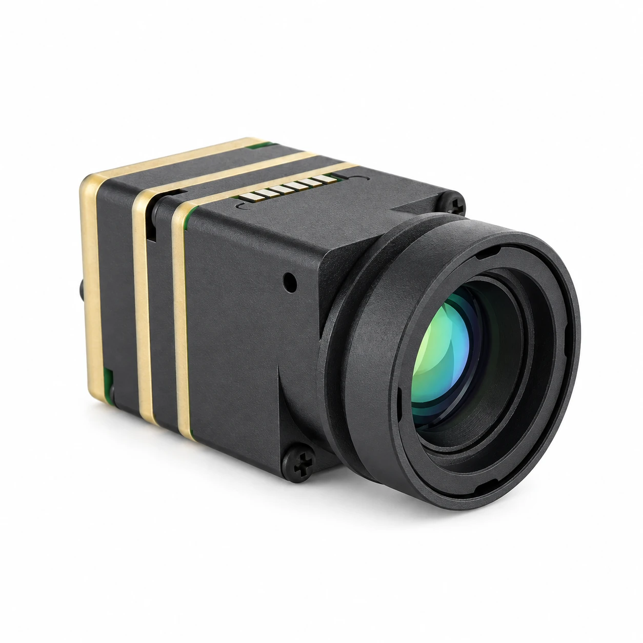
CAMCUDA SuperMini 640 / 640T family appearance. Bare-core reference: 13 × 13 × 13.4 mm and <3.5 g, excluding optics and expansion boards; this photograph does not define assembly dimensions.
CAMCUDA SuperMini 640 / 640T Ultra-Light LWIR Thermal Camera Module
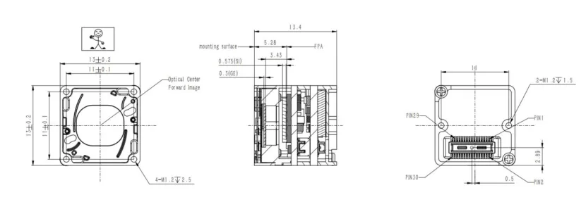
The CAMCUDA SuperMini 640 series represents low-SWaP thermal engineering pushed to the limit. Pairing a 640 × 512 uncooled VOx focal plane array, an ultra-fine 8 μm pixel pitch, and a sub-3.5 gram bare core mass, its bare core measures 13 × 13 × 13.4 mm; dimensions and mass exclude optics and expansion boards. Typical core power is ≤0.5 W at 25°C, excluding the expansion board. Budget separately for the selected optics, carrier, cables and enclosure when evaluating a micro-drone or micro-gimbal installation.
VOx Array
Pixel Pitch
Bare Core Mass
Typical core power at 25°C
SuperMini Bare-Core Models & Electrical Pinout Reference
The series comes factory-configured as the SuperMini 640 (50 Hz imaging only) or the SuperMini 640T (30 Hz thermography). The imaging model documents BT656 and 2-lane MIPI paths; the thermographic model documents CDS3 and MIPI image/temperature-data paths. BT656 and MIPI cannot operate simultaneously.
The 640T measurement ranges are −20°C to +150°C and +100°C to +650°C, with typical accuracy of ±2°C or ±2% of reading at ambient −20°C to +60°C. These temperature specifications do not apply to SuperMini 640 or AeroMini. See the 30-pin definitions, power requirements and 640T MIPI format in Product Manual V1.0.0.
| Interface Path | Published Requirement | Integration Note |
|---|---|---|
| MAIN_POWER | 3.8 – 5.2 V (5.0 V typical) | 10 mV p-p maximum noise ripple |
| +3.3 V Rail | 3.28 – 3.32 V | 10 mV p-p maximum noise ripple |
| +1.8 V Rail | 1.78 – 1.82 V | 1 mV RMS maximum noise (1 Hz – 50 kHz) |
| Digital Video | 8-bit LVCMOS; 2-lane MIPI | 640: BT656 / MIPI • 640T: CDS3 / MIPI; BT656 and MIPI are not simultaneous |
| Control / Comm | UART (1.8 V logic level) | Hirose DF40C-30DP-0.4V(51) 30-pin interface |
Published SuperMini Athermal Lens Configurations (F1.0): 3.7 mm (90.0° × 68.2°, 2.16 mrad) | 6.1 mm (46.6° × 37.6°, 1.31 mrad) | 8.7 mm (40.0° × 32.2°, 0.92 mrad) | 11.0 mm (24.9° × 20.0°, 0.73 mrad).

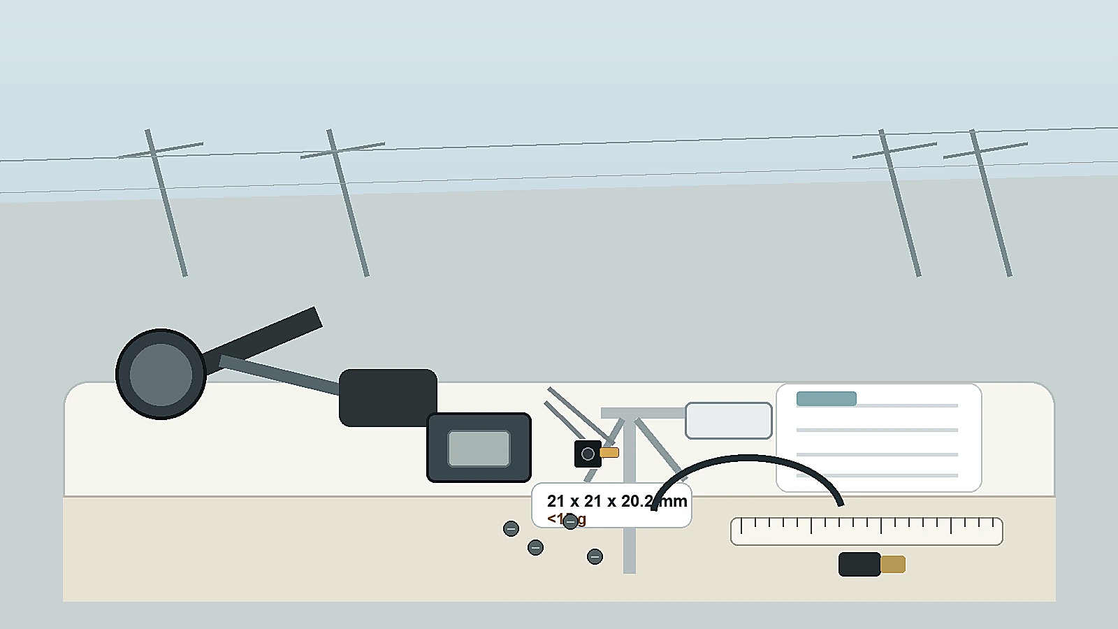
CAMCUDA AeroMini 640 family appearance. Reference: 21 × 21 × 28 mm and <20 g, excluding lens and flange; this photograph does not establish the selected lens or assembly dimensions.
CAMCUDA AeroMini 640 LWIR Thermal Camera Core
The CAMCUDA AeroMini 640 module is a 640 × 512, 12 μm uncooled VOx core for OEM thermal payload integration. The current product page specifies NETD ≤30 mK at 25°C, F/1.0. Eight lens focal lengths are selectable in the current configurator: 4, 7, 9, 13, 18, 25, 35 and 50 mm. Additional 15, 60 and 75 mm entries are listed for enquiry; this does not establish current stock or orderability for those lenses. Confirm the selected lens, board and complete assembly before integration.
VOx Array
Pixel Pitch
Excludes lens and flange
Non-radiometric factory options
System Architecture & Optical Coverage
AeroMini has two camera versions. The non-radiometric version is supplied at 60 Hz by default, with an optional 30 Hz factory configuration; it does not measure temperature. The separate 25 Hz radiometric version covers −20°C to +550°C with documented 9, 13 or 18 mm lenses and is currently out of stock, available for supply enquiries only. Its accuracy and RAW data format require confirmation.
Video, serial interfaces and the approved power input depend on the selected board. The illustrated 16-pin USB/CVBS and 26-pin MIPI/DVP boards label POWER_IN1 / POWER_IN2 as 5 V only; do not apply 12 V or transfer these pin definitions to the Type-C board or SuperMini. See the AeroMini datasheet and AeroMini developer-resource FAQ for model-specific resources.
For an AeroMini 9 mm installation, request the mechanical drawing for the ordered lens and board assembly. The public AeroMini STEP resource represents the 7 mm version; SuperMini drawings describe a different product. Match developer files, firmware, interface and host receiver to the ordered configuration.
| Optics (F1.0) | Published FOV (H × V) | Radiometric Support | Application Domain |
|---|---|---|---|
| 4 mm / 7 mm | Wide-Angle / Broad Coverage | Imaging Only | Close-range imaging / Navigation evaluation |
| 9 mm / 13 mm / 18 mm | 48.7° × 38.6° (9mm) – Medium | 25 Hz radiometric version: supply enquiry only | Solar Farm Inspection / Electrical Utility Scouting |
| 25 / 35 / 50 mm; 60 / 75 mm enquiry | Narrow Telephoto / High Stand-Off | Imaging Only | High-Altitude Tactical Reconnaissance & Perimeter Tracking |
6. Mechanical Envelope, Thermal Heat Paths & Gimbal Dynamics
Integrating a CAMCUDA SuperMini 640 / 640T or AeroMini 640 into a brushless UAV gimbal requires close attention to power integrity, thermal conduction paths, complete-assembly mass and harness strain relief. Validate image stability, temperature rise and motor control on the assembled payload before flight. The SuperMini bare-core requirements below do not define AeroMini board wiring.
1. Power Rail Ripple & Noise Suppression
Microbolometers sense temperature-dependent resistance changes. Supply noise can affect detector/readout and image quality, so design and measure every required rail against the selected core or carrier-board specification. The following rail and UART limits apply to the SuperMini bare core.
- ⚠️ SuperMini MAIN_POWER (3.8 V to 5.2 V): Meet the published 10 mV p-p maximum noise limit. Select and validate regulators, filtering, current capacity, dropout and thermal behavior for the aircraft supply; a regulator family name alone does not establish compliance.
- ⚠️ SuperMini Additional Supply Rails: +3.3 V must be 3.28–3.32 V with 10 mV p-p maximum noise; +1.8 V must be 1.78–1.82 V with 1 mV RMS maximum noise (1 Hz to 50 kHz). All three required rails and the manual’s power sequence must be implemented.
- ⚠️ SuperMini Logic Level Shifting: UART uses 1.8 V logic. Use compatible signaling or a properly designed level shifter; do not connect incompatible 3.3 V or 5 V signaling directly. AeroMini serial levels and wiring require the matched board guide.
2. Thermal Dissipation & Conduction Pathways
At 25°C, SuperMini specifies ≤0.5 W typical core power excluding the expansion board; AeroMini specifies <0.5 W typical module consumption, with complete-kit consumption potentially different. Budget for boards, optics-related actuators and nearby electronics as well as the core. A sealed gimbal needs a validated conduction path and thermal measurements because internal gradients can affect calibration and image stability.
- ⚙️ Design a conduction path from the core to the gimbal structure. Select any gap pad by contact area, thickness, thermal resistance and allowable mechanical load, then verify the resulting core temperature and image stability.
- ⚙️ Evaluate heat transfer from nearby video transmitters, companion computers and motor drivers, and provide spacing or thermal isolation where the measured temperature budget requires it.
- ⚙️ Evaluate optical-barrel temperature gradients and focus over the specified operating range; an athermal lens designation does not guarantee unchanged focus during every transient.
3. Gimbal Balancing & Hirose Flex Harness Routing
Micro-gimbals run small, low-torque brushless motors that hate mechanical resistance and center-of-gravity (CG) offsets.
- ⚙️ CG Alignment: When swapping lenses (say, moving from a 3.7 mm wide-angle to an 11 mm narrow-field lens), recalculate the center of mass and rebalance the gimbal cradle so the payload CG sits precisely on the pitch and roll rotational axes.
- ⚙️ Flex Harness Routing: For SuperMini’s 30-pin Hirose DF40C connection, plan the matched cable’s bend radius, strain relief and travel through the full gimbal range. Cable stiffness and tension can add torque; measure their effect on balancing and stabilization. AeroMini uses board-specific connections, so this 30-pin reference is not its harness pinout.
For detailed commercial licensing terms, OEM integration warranties, and supply agreements, check out our standard terms of service.
7. Frequently Asked Questions (FAQ)
Which video and communication interface should I choose for custom drone payload integration?
What is the practical difference between an imaging-only and a radiometric IR camera on a drone?
How do SWaP (Size, Weight, and Power) constraints impact thermal payload design on compact drones?
📚 References & Further Reading
- Industry Standard: MIPI Alliance CSI-2 Overview
- Industry Reading: sUAS News — Unmanned Aviation Industry Insights
- Related Guide: High-Resolution Thermal Imaging Camera OEM Selection Guide
- Related Guide: Thermal Camera Core Selection: Interface, Resolution & Integration Checklist
- Corporate Terms: CAMCUDA Terms of Service & OEM Hardware Licensing