Drone with Thermal Imaging: OEM Payload & Core Integration Guide
Drone with Thermal Imaging: OEM Payload & Core Integration Guide
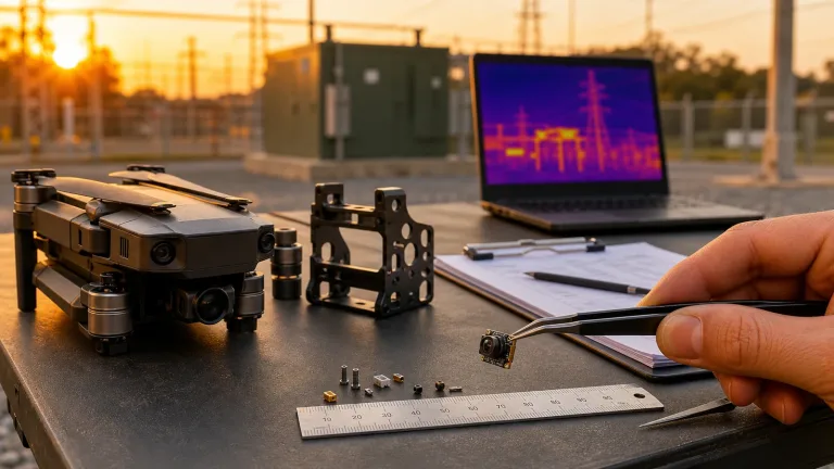
Designing a reliable, high-performance drone with thermal imaging payload has historically forced engineering teams into a frustrating corner. You either shell out tens of thousands of dollars for closed-ecosystem, heavily marked-up turnkey enterprise rigs, or you’re stuck trying to wire raw microbolometer silicon onto custom PCBs from scratch. Look, as aerial inspections across high-voltage utility grids, utility-scale solar farms, search-and-rescue operations, and tactical reconnaissance shift rapidly toward custom autonomous systems, original equipment manufacturers (OEMs) and payload integrators need open, modular hardware. Building an airborne long-wave infrared (LWIR) rig that actually survives real-world flight operations means balancing aggressive Size, Weight, Power, and Cost (SWaP-C) limits against optical performance and clean video pipelines.
Here’s the deal: dropping an uncooled OEM thermal imaging core into a micro, multirotor, or fixed-wing unmanned aerial vehicle (UAV) demands a complete, ground-up understanding of sensor physics, germanium optics, data protocols, electrical noise suppression, and computer vision pipelines. This engineering blueprint walks through the entire hardware and software development lifecycle. We’ll cover everything from calculating real-world Ground Sample Distance and selecting factory-calibrated lenses to implementing low-latency video streaming across MIPI, USB UVC, and CVBS protocols. Let’s get into the technical nuts and bolts required to build mission-ready thermal UAV payloads.
Table of Contents
- 👉 1. Sensor Physics & LWIR Detection in Airborne Environments
- 👉 2. SWaP-C Optimization: Thermal Core Mechanical & Electrical Integration
- 👉 3. UAV Optics Selection: IFOV, FOV, and Johnson’s Criteria Mapping
- 👉 4. Data Interfaces & Video Pipelines: CVBS, USB UVC, MIPI, and SPI
- 👉 5. Edge AI, Companion Computers, and Computer Vision Pipelines
- 👉 6. OEM Thermal Core Benchmark: CAMCUDA FlexMini 640 vs. TC160-NF
- 👉 7. Gimbal Integration, Thermal Dissipation, and EMI Shielding
- 👉 8. Deep-Dive Integration FAQ
1. Sensor Physics & LWIR Detection in Airborne Environments
Airborne thermal imaging relies entirely on collecting electromagnetic radiation within the Long-Wave Infrared (LWIR) atmospheric transmission window (8–14 μm). Unlike standard electro-optical (EO) visible daylight sensors that need reflected ambient light, LWIR sensors detect passive blackbody radiation emitted by every physical object above absolute zero (0 Kelvin), governed by Planck’s Law and the Stefan-Boltzmann Law (j* = εσT⁴). When you’re flying at altitude, LWIR radiation cuts clean through atmospheric obscurants like particulate haze, industrial smog, light maritime fog, and pitch-black conditions, giving your platform true 24/7 all-weather mission capability.
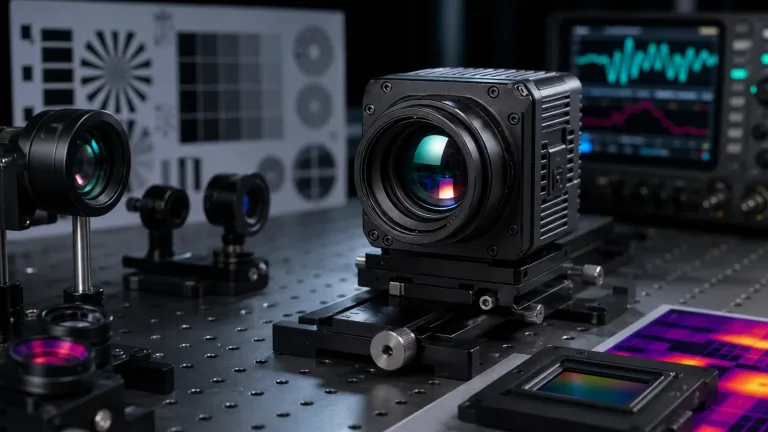
The radiative path starts right at the target surface. The thermal signature emitted by the target is governed by its surface emissivity (ε), which mixes with whatever background radiation is reflecting off it. This radiant energy travels up through the air column, where path absorption in the 8–14 μm band is minimal compared to Mid-Wave Infrared (MWIR) or Short-Wave Infrared (SWIR) bands that suffer from solar reflection and clutter during midday flights. The incoming photon stream is focused through specialized optics—typically single-crystal Germanium or Chalcogenide glass with antireflective coatings—and onto the focal plane array (FPA) of an uncooled microbolometer sensor.
Microbolometer Architecture: VOx vs. a-Si
In the shop, the heart of any uncooled thermal package is the microbolometer FPA. Each pixel is an infrared-absorbing membrane suspended above silicon readout integrated circuitry (ROIC) on micro-machined bridge structures that provide thermal isolation. The two primary active sensing materials you will run across are:
- ⚙️ Vanadium Oxide (VOx): Delivers a strong Temperature Coefficient of Resistance (TCR ≈ -2% to -3%/K) and inherently low 1/f electrical flicker noise. VOx provides exceptional thermal sensitivity, hitting Noise Equivalent Temperature Differences (NETD) of ≤ 30 mK. This lets the core pull out razor-thin temperature deltas across concrete pads, soil beds, dense tree cover, and composite materials mid-flight.
- ⚙️ Amorphous Silicon (α-Si): Offers standard CMOS foundry manufacturing and lower bill-of-materials costs, but it generally exhibits higher 1/f noise and lower baseline sensitivity (typically NETD 40–50 mK).
CAMCUDA AeroMini 640 uses a 640 × 512 uncooled VOx detector for compact payload integration. Confirm the camera version, factory frame rate, lens and interface before design approval. The non-radiometric version produces thermal images without calibrated temperature measurements; the 25 Hz radiometric version is available for supply enquiries only.
Non-Uniformity Correction (NUC) and Shutterless Operation
Every individual pixel on a microbolometer array has slightly different resting resistance, bias characteristics, and thermal responsivity. When you take an aircraft into the air, the core gets hit with sudden temperature swings caused by prop downwash, atmospheric altitude lapse, and dynamic forward airspeed cooling. Thermal cores keep drift under control using Non-Uniformity Correction (NUC):
- ⚙️ Mechanical Shutter NUC: A physical solenoid drops a mechanical flag directly in front of the detector for 100–300 ms to establish a flat thermal baseline. While rock-solid for absolute temperature accuracy, that split-second video freeze can mess up autonomous flight navigation or cause edge tracking loops to drop their targets.
- ⚙️ Shutterless / Scene-Based Non-Uniformity Correction (SBNUC): Smart algorithmic processing tracks pixel drift over time by analyzing scene motion and statistical frame profiles, wiping out fixed-pattern noise on the fly without interrupting real-time video feeds during critical flight maneuvers.
2. SWaP-C Optimization: Thermal Core Mechanical & Electrical Integration
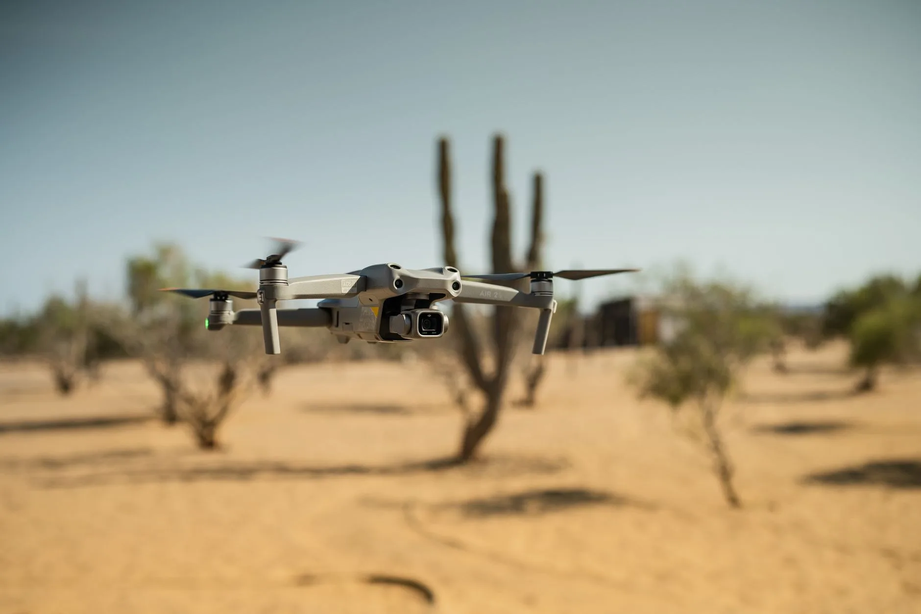
When you sit down to engineer a drone with thermal imaging payload, SWaP-C (Size, Weight, Power, and Cost) dictates your total flight time, gimbal motor selection, and battery sizing. Micro airframes (such as sub-250g Category 1 UAVs) require stripped-down, ultralight cores, while medium-altitude enterprise platforms can handle heavier, swappable optics, high-bandwidth digital pipelines, and wide input voltage regulation.
Mechanical Envelope & Mass Budgets
In aerial systems, every single gram you add to your payload cuts directly into flight endurance. You can model this hover endurance penalty using the classic mass ratio relationship:
Δt_flight ≈ -(Δm_payload / m_total) · t_hover
Using a featherweight core like the CAMCUDA FlexMini 640 (which weighs just 23.1 g bare) gives you the margin to build a complete, sub-100 g 2-axis stabilized brushless gimbal setup. If you are designing secondary auxiliary payloads or proximity sensors, sub-tier modules like the TC160-NF 160×120 LWIR Thermal Imaging Module can drop dedicated thermal tracking onto an airframe at under 10 grams total footprint.
Electrical Power Distribution and Thermal Dissipation
Getting your electrical architecture right requires managing power rails cleanly without dumping thermal load into your sensor housing:
- ✅ Wide Input Voltage Handling: Stepping down standard 4S–6S flight packs (14.8 V to 22.2 V) usually means adding switching buck regulators that radiate high-frequency switching noise straight into sensitive analog video lines. Modules that support 5–24 V DC direct input can run directly off flight controller power rails or the main battery distribution board without bulky external DC-DC step-down hardware.
- ✅ Sub-Watt Power Consumption: Running a thermal core at under 0.7 W dramatically eases conductive thermal management inside sealed payload housings. If heat builds up inside an enclosed pod, it radiates right back onto the microbolometer FPA, introducing thermal drift, fixed pattern noise, and radiometric measurement errors.
3. UAV Optics Selection: IFOV, FOV, and Johnson’s Criteria Mapping
Thermal optical systems behave nothing like standard visual glass. Visible glass completely blocks long-wave infrared energy. That means your optical elements must be cut and polished from single-crystal Germanium (Ge) or specialized Chalcogenide glass elements with tough anti-reflective coatings. The physical aperture needs to maintain a fast F1.0 transmission rating to maximize photon flux landing on the 12 μm microbolometer detector array.
Calculating Spatial Resolution: IFOV & FOV
Instantaneous Field of View (IFOV) defines the exact angular footprint captured by a single pixel, establishing the smallest physical detail your camera can resolve from a specific altitude:
IFOV (mrad) = Pixel Pitch (μm) / Focal Length (mm)
Ground Sample Distance (GSD) = 2 · Range · tan(IFOV / 2) ≈ Range · IFOV
Take the CAMCUDA FlexMini 640 with its 12 μm pixel pitch and a 9.1 mm lens: the resulting IFOV is 1.31 mrad. Cruising at an operational altitude of 100 meters, your Ground Sample Distance comes out to roughly 13.1 cm per pixel on the ground.
Johnson’s Criteria Range Modeling for Airborne Missions
Johnson’s criteria mathematically break down target acquisition ranges across a standard human target profile (1.8 m × 0.5 m):
- ⚙️ Detection (1.5 cycles / 3 pixels across target dimension): The operator or software confirms an object is present in the field of view.
- ⚙️ Recognition (6.0 cycles / 12 pixels across target dimension): The system discriminates what class of object it is (human, livestock, or vehicle).
- ⚙️ Identification (12.0 cycles / 24 pixels across target dimension): The system discriminates specific operational features (a person carrying gear or specific equipment details).
| Lens Focal Length | Field of View (H × V) | IFOV | Detection Range | Recognition Range | Identification Range |
|---|---|---|---|---|---|
| 4.9 mm | 76.2° × 64.2° | 2.45 mrad | 476 m | 119 m | 60 m |
| 9.1 mm | 45.8° × 37.3° | 1.31 mrad | 884.72 m | 221.18 m | 110.59 m |
| 13.0 mm | 33.0° × 26.6° | 0.92 mrad | 1,263.89 m | 315.97 m | 157.99 m |
| 19.0 mm | 22.9° × 18.4° | 0.63 mrad | 1,847.22 m | 461.81 m | 230.90 m |
| 35.0 mm | 12.5° × 10.0° | 0.34 mrad | 3,402.78 m | 850.69 m | 425.35 m |
Wide lenses (4.1 mm to 9.1 mm) are your workhorses for close-quarter structural inspection, indoor search operations, and situational awareness where wide coverage prevents obstacle collisions. Narrow lenses (13 mm to 35 mm) are mandatory for utility work, high-tension powerlines, and perimeter surveillance where the aircraft has to stay at safe standoff distances (>100 m). To explore full optical choices, review the CAMCUDA Thermal Products Catalog.
4. Data Interfaces & Video Pipelines: CVBS, USB UVC, MIPI, and SPI
Picking your video interface dictates video stream latency, companion computer CPU overhead, and downstream video transmitter hardware selection:
- ✅ Composite Analog Video (CVBS – PAL/NTSC): Offers glass-to-glass latency under 20 ms. Analog CVBS connects right to standard 5.8 GHz analog video transmitters (FPV VTX), delivering an ultra-lightweight, zero-fuss live feed for manual piloting and manual search runs. The wiring uses a simple 5-pin connection (Rx, Tx, CVBS, GND, VCC).
- ✅ USB UVC (Universal Video Class): Provides a plug-and-play driverless interface for Linux companion boards (Raspberry Pi Compute Module 4, NVIDIA Jetson Orin Nano, Radxa Zero). The camera presents directly as a standard
/dev/video*V4L2 device over a 4-pin physical interface (USB-VDD, D-, D+, GND). - ⚙️ MIPI CSI-2: A high-throughput digital bus that connects straight into onboard Image Signal Processors (ISPs) and host processors. MIPI delivers raw radiometric data arrays with sub-10 ms latency, making it the top choice for onboard Edge AI object detection and multi-spectral EO/IR sensor fusion.
- ⚙️ Serial Peripheral Interface (SPI): Tailor-made for low-power microcontrollers (STM32, ESP32) pulling frame arrays from compact modules like the TC160-NF for thermal triggers, proximity checking, and lightweight IoT tasks.
Before locking in your enclosure design and routing your carrier board, review our Thermal Camera Suppliers OEM RFQ Checklist to verify physical pin assignments, connector footprints, and mating orientations.
5. Edge AI, Companion Computers, and Computer Vision Pipelines
Modern thermal drones operate as autonomous edge platforms. Hooking up a 640×512 50 Hz thermal core over USB UVC or MIPI to an embedded Linux System-on-Module (SoM) lets you run real-time inference on the drone without needing high-bandwidth ground control data links.
The companion computer grabs raw frames from the core, processes the visual data using OpenCV to flag high-temperature anomalies, and streams tracking offsets over MAVLink directly into your autopilot (running PX4 or ArduPilot) for autonomous target tracking.
import cv2
import numpy as np

def init_thermal_stream(device_index=0, width=640, height=512, fps=50):
    """Initializes the UVC thermal camera stream via V4L2 backend."""
    cap = cv2.VideoCapture(device_index, cv2.CAP_V4L2)
    cap.set(cv2.CAP_PROP_FRAME_WIDTH, width)
    cap.set(cv2.CAP_PROP_FRAME_HEIGHT, height)
    cap.set(cv2.CAP_PROP_FPS, fps)
    cap.set(cv2.CAP_PROP_CONVERT_RGB, False)

    if not cap.isOpened():
        raise RuntimeError(f"Failed to open thermal core on /dev/video{device_index}")
    return cap

def process_hotspot_telemetry(frame, temp_threshold_val=200):
    """
    Identifies high-temperature pixel clusters and generates bounding coordinates
    for companion computer MAVLink payload targeting.
    """
    if len(frame.shape) == 3:
        gray = cv2.cvtColor(frame, cv2.COLOR_BGR2GRAY)
    else:
        gray = frame

    # Apply Gaussian smoothing to reduce microbolometer temporal noise
    blurred = cv2.GaussianBlur(gray, (5, 5), 0)

    # Threshold upper thermal intensity levels
    _, thresh = cv2.threshold(blurred, temp_threshold_val, 255, cv2.THRESH_BINARY)

    # Extract structural contours of thermal anomalies
    contours, _ = cv2.findContours(thresh, cv2.RETR_EXTERNAL, cv2.CHAIN_APPROX_SIMPLE)

    detections = []
    for cnt in contours:
        if cv2.contourArea(cnt) > 25:  # Filter out single hot-pixel noise
            x, y, w, h = cv2.boundingRect(cnt)
            detections.append((x, y, w, h))
            cv2.rectangle(frame, (x, y), (x + w, y + h), (0, 0, 255), 2)

    return frame, detections

if __name__ == "__main__":
    stream = init_thermal_stream(0)
    print("[INFO] Thermal payload vision pipeline initialized.")

    while True:
        ret, raw_frame = stream.read()
        if not ret:
            break

        annotated_frame, hotspots = process_hotspot_telemetry(raw_frame)

        cv2.imshow("Airborne Thermal Edge Processing", annotated_frame)
        if cv2.waitKey(1) & 0xFF == ord('q'):
            break

    stream.release()
    cv2.destroyAllWindows()
6. OEM Thermal Core Benchmark: CAMCUDA FlexMini 640 vs. TC160-NF
Your hardware choice comes down to mission parameters, airframe payload capacity, electrical bus limits, and compute architecture. Here is a technical breakdown of two field-tested uncooled LWIR thermal modules ready for OEM platform integration.
Product Profile: CAMCUDA FlexMini 640 Uncooled VOx Thermal Imaging Camera Module
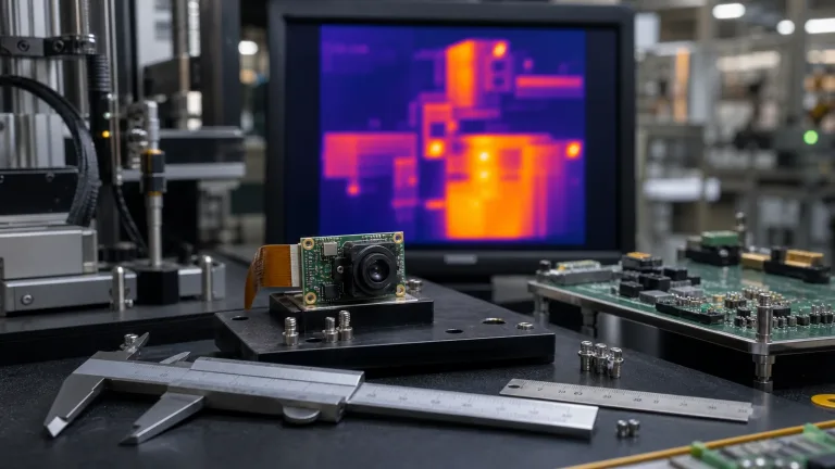
The CAMCUDA FlexMini 640 packs a 640×512 uncooled VOx array with a 12 μm pixel pitch, ≤30 mK NETD sensitivity, and a responsive 50 Hz frame rate inside a compact 23.1 g chassis. Built for multi-axis aerial gimbals, industrial inspection pods, and search payloads, it handles 5–24 V DC direct input while pulling under 0.7 W.
| Detector Type | Uncooled VOx Focal Plane Array |
|---|---|
| Resolution & Pitch | 640 × 512 pixels | 12 μm pixel pitch |
| Thermal Sensitivity (NETD) | ≤ 30 mK reference (@ F1.0, 25°C) |
| Frame Rate & Latency | 50 Hz | < 20 ms reference delay |
| Spectral Range | 8 – 14 μm (LWIR) |
| Input Voltage & Power | 5 – 24 V DC wide-voltage | < 0.7 W consumption |
| Output Interfaces | CVBS (PAL analog), USB UVC, or MIPI |
| Factory Lens Options | 4.1 mm, 4.9 mm, 9.1 mm, 13 mm, 19 mm, 35 mm (F1.0) |
| Module Weight & Temp | 23.1 g bare core | -20°C to +60°C operating |
Product Profile: TC160-NF 160×120 Uncooled LWIR Thermal Imaging Module
The TC160-NF is an ultra-small, low-drain uncooled LWIR sensor built for micro quadcopters, auxiliary payload sensing, smart security monitors, and compact industrial IoT devices. It runs off a clean 3.3 V rail, draws only ~76–78 mW, and hooks straight into MCUs via an SPI interface over a 10-pin 0.5 mm pitch FPC ribbon.
| Detector Model & SKU | TC160-NF (SKU: MI1602M5S) |
|---|---|
| Resolution & Total Pixels | 160 × 120 pixels | 19,200 pixels |
| Detector Pitch & Spectral | 35 μm reference pitch | 8 – 14 μm LWIR band |
| Frame Rate | Up to 25 FPS |
| Field of View (D/H/V) | 56° / 45° / 34° narrow-FOV fixed optical path |
| Power Supply & Load | 3.3 V supply | ~76 – 78 mW low-power operation |
| Host Interface & Connector | SPI interface | 10-pin FPC (0.5 mm pitch) |
| Calibration & Temp Range | Factory calibrated | -20°C to +85°C operating reference |
7. Gimbal Integration, Thermal Dissipation, and EMI Shielding
Mounting an OEM thermal core inside a 3-axis brushless gimbal assembly requires addressing mechanical resonance, flight vibrations, heat transfer, and electromagnetic interference (EMI).
Vibration Isolation & Mechanical Mount Resonance
High-RPM drone motors and props generate micro-vibrations between 50 Hz and 500 Hz. When you fly narrow lenses (like 19 mm or 35 mm optics), those high-frequency micro-vibrations turn into rapid image jitter and rolling artifacts.
- ⚙️ Tuned Silicone Dampers: Isolate the payload mount with shore-hardness-rated (30A to 50A) silicone vibration bobbins sized precisely for your payload mass.
- ⚙️ Center of Gravity (CoG) Balancing: Align the core’s center of mass with the gimbal pitch and roll rotation axes so the brushless motors don’t fight steady-state holding loads or overheat in hover.
EMI Shielding on High-Gain Analog Video Paths
Microbolometer sensors generate tiny analog voltage signals internally before digitizing them. Strong RF energy from high-power 2.4 GHz/5.8 GHz transmitters, 900 MHz telemetry radios, or noisy ESC power leads can inject horizontal rolling bars right across your thermal image.
- ⚙️ Chassis Grounding: Bond the thermal module’s aluminum chassis directly to the gimbal ground plate.
- ⚙️ Shielded Coaxial Leads: Route CVBS video signals over micro-coaxial cable (RG178 or shielded twisted pairs) with the shield grounded at the camera connector.
- ⚙️ Ferrite Line Filters: Place surface-mount ferrite beads on DC input lines right at the core interface to suppress high-frequency ESC switching ripple.
To pull 3D CAD step files, verify interface pinouts, or discuss technical support for your airframe integration, contact our engineering application team.
8. Deep-Dive Integration FAQ
How can engineering teams build an affordable drone with thermal imaging without buying overpriced turnkey enterprise platforms?
Can a high-resolution 640×512 thermal core be integrated into sub-250g or lightweight micro drones?
How do you select the correct lens focal length for UAV industrial inspection versus search operations?
📚 References & Further Reading
- Industry Standard: InfraTec Infrared Cameras
- Computer Vision Framework: OpenCV Open Source Computer Vision Library
- Related Guide: Thermal Camera Suppliers OEM RFQ Checklist
- Hardware Catalog: CAMCUDA OEM Thermal Sensors & Modules Directory