hd thermal imaging camera core: 4 Reliable System-Fit Decisions Before Sample Orders
Procurement note for OEM engineers and UAV payload buyers
hd thermal imaging camera core: 4 Reliable System-Fit Decisions Before Sample Orders
A buyer can ask for an hd thermal imaging camera core and still receive the wrong sample. The problem is not the word HD by itself. The problem is that resolution, video path, lens/FOV, mechanical envelope, and procurement documents are often discussed by different people after the sample is already on the bench.
Technical author: Daniel · Hardware Support
Sales contributors: Vivian, Lena and Sophie
Quick answer
An hd thermal imaging camera core should be evaluated as a system component, not as a resolution label. Before ordering samples, confirm the detector class, lens/FOV path, host video and control interfaces, mechanical envelope, field workflow, and documentation needs. CAMCUDA’s Featured AeroMini 640 is a 640 x 512 uncooled LWIR module with distinct USB + CVBS + MIPI and Type-C + CVBS tailboard choices. Its 21 x 21 x 28 mm and <20 g references exclude the lens and flange. Non-radiometric imaging is 60 Hz by default or 30 Hz by factory configuration; the 25 Hz radiometric version requires an availability enquiry. Confirm the complete assembly, host path, lens, drawings and configuration-specific procurement documents during RFQ.
hd thermal imaging camera core searches usually start too late in the system
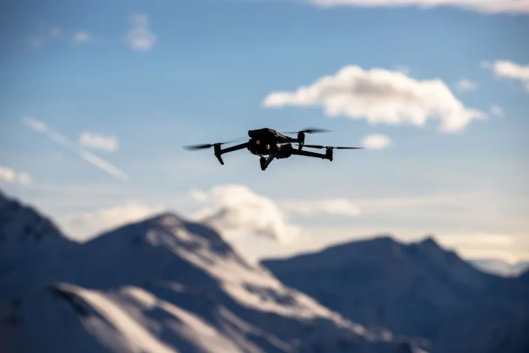
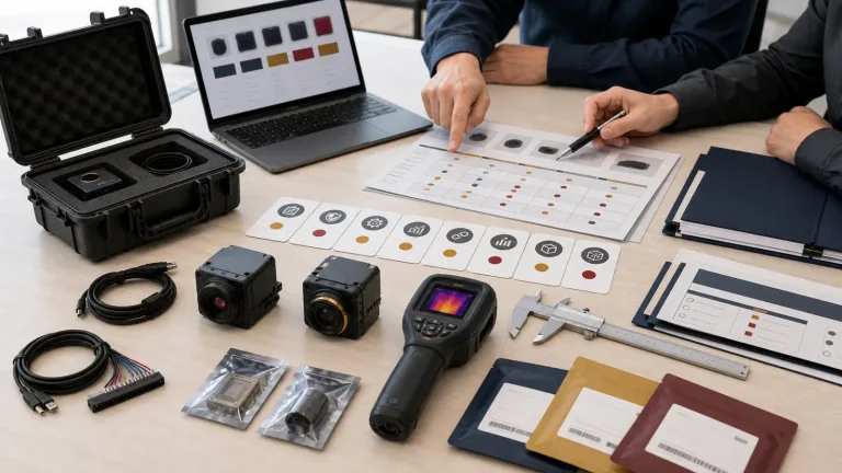
The sample box arrives on a Thursday afternoon. The module image looks sharp enough on a laptop, but the payload engineer has not checked where the cable exits. The product manager has promised a compact drone bracket. Procurement needs a document path for a North America customer. The field team wants a low-latency viewing path that may still involve analog video. Everyone thought they had ordered an hd thermal imaging camera core. What they really ordered was an unresolved system decision.
That is the buyer moment this article addresses. “HD” can mean useful thermal detail, but a thermal module only becomes useful when the host board, video interface, lens, enclosure, field workflow, and documentation package agree with one another. Record those requirements together before ordering: which host receives the image, which receiver is used in the field, how the module fits, and what evidence each team needs to approve the sample. For this buyer, the real decision is whether the core can become a repeatable product.
Translate the hd thermal imaging camera core request into a shared acceptance plan. Engineering should specify the lens, host interface and assembly envelope; field operations should define the target scene and viewing workflow; procurement should list the destination, quantities and required documents. The focus is component-level sourcing: an RFQ that all three teams can use to approve the same configuration.
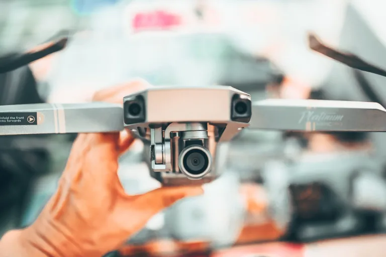
Start with the Featured CAMCUDA AeroMini 640 for the selected lens and tailboard, and compare the Featured SuperMini 640 / 640T when the host design can accommodate a separate bare-core integration. Both use 640 x 512 detectors. A generic lower-resolution sensing module can be useful for a defined sensing zone, but it serves a different requirement from the HD-class UAV or OEM imaging-core discussion here.
Four decisions before an hd thermal imaging camera core sample order
1. Decide what HD must prove in the field
Resolution is not a field result by itself. A 640 x 512 LWIR module can provide more thermal image detail than a low-resolution sensing module, but the buyer still has to define target size, distance, scene width, thermal contrast, lens requirement, and operator workflow. An hd thermal imaging camera core for a drone payload has a different job than one used in a fixed outdoor monitoring device or an embedded industrial inspection product. Use the thermal imaging calculator for a preliminary geometry check, then validate the selected optics and target in the intended scene; a geometry estimate does not guarantee detection or temperature-measurement performance.
Current industrial vision writing often frames sensing as part of a larger workflow. NVIDIA’s industrial AI coverage, including its robotics and industrial AI examples, is useful inspiration because it treats cameras, edge processing, and operations as connected systems. Micron’s computer vision explainer makes a similar point from the data side: images are useful when the system can analyze and act on them. For a component buyer, the shared lesson is that the sensor must serve the decision made by the system; these broad examples do not establish any particular thermal core’s capabilities.
2. Decide the video and control path before the bracket is drawn
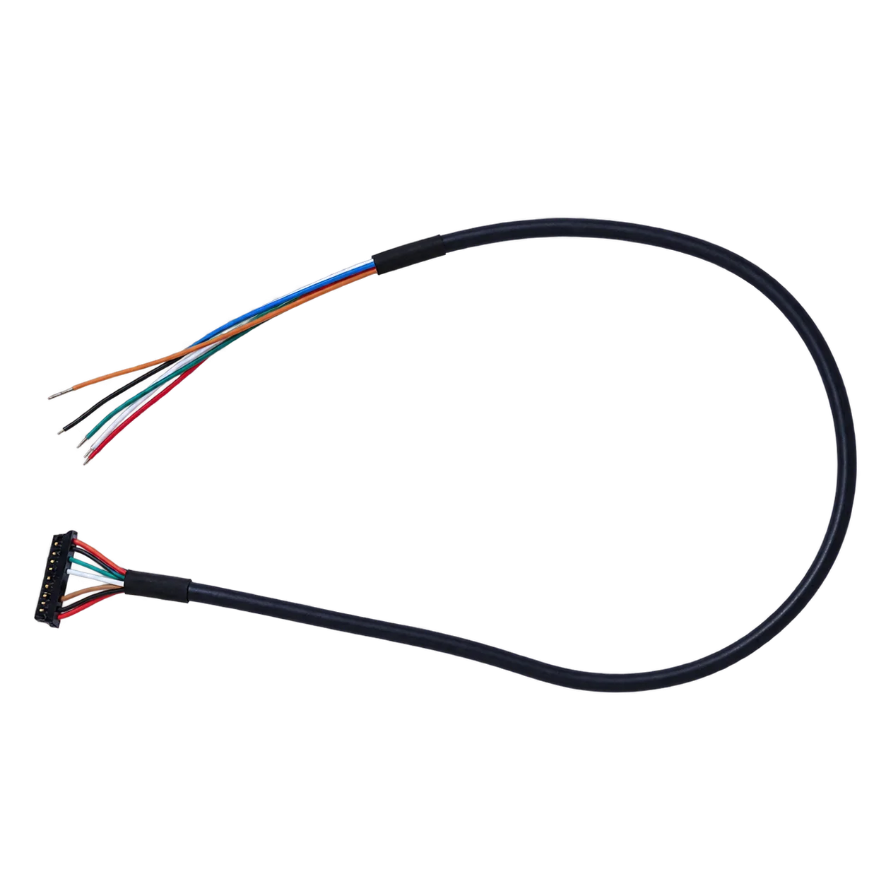
A late interface change can break a good mechanical design. AeroMini offers distinct USB + CVBS + MIPI and Type-C + CVBS tailboards. Select the board before approving the host connection, cable and control path. The family lists UART, RS232 and RS422 options according to the selected board; the illustrated 16-pin USB/CVBS connector is labeled RS232, which does not establish RS422 on that connector. Confirm the actual video format, rate and receiver compatibility during RFQ when the project needs legacy displays, analog recorders, low-latency monitoring, drone video transmission, or an OEM retrofit path.
This is one of the most believable mistakes in module sourcing: the team tests USB video at a desk, then discovers the field receiver expects another path. A practical RFQ line is better than a vague request: “Please confirm the selected AeroMini tailboard, USB video format for development, board-specific serial control and CVBS output for our existing receiver.” Review the AeroMini datasheet with the product FAQ’s Linux driver, examples and SDK guidance, matching the documents to the board, firmware, host, output format and rate before bench validation.
3. Decide whether the module is physically small enough after cables and lens
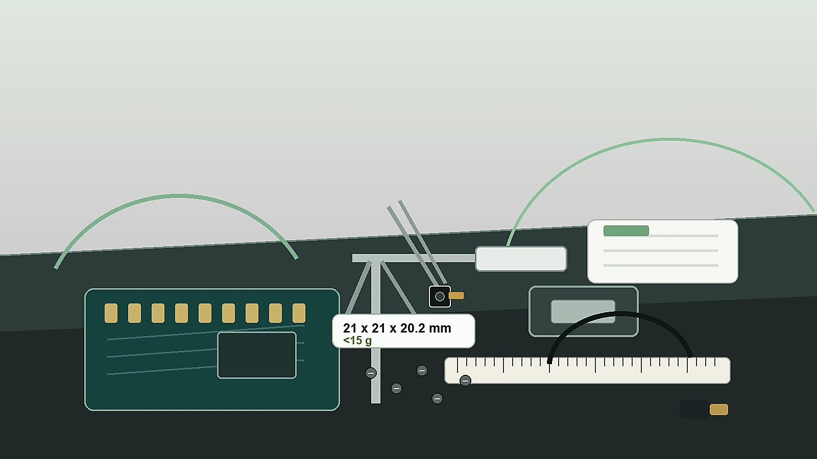
AeroMini’s published 21 x 21 x 28 mm dimensions and <20 g weight exclude the lens and flange. Those numbers are only the start. Request the complete assembly CAD and mass for the selected lens and tailboard. The buyer still needs lens clearance, FPC or connector access, cable bend radius, expansion-board expectations, enclosure window position, heat path, vibration requirements, and service access.
A compact hd thermal imaging camera core should be measured against the actual host product. If the bracket blocks the connector or the cable exits into the enclosure wall, the detector spec will not save the build.
4. Decide the documentation path while the quote is open
Procurement should not receive the project only after the image looks good. North America, industrial monitoring, drone inspection, security monitoring, utility, and government-adjacent buyers may need datasheets, drawings, interface references and applicable compliance-related review materials. If an NDAA statement is required, request it for the exact configuration and intended use; document availability and procurement eligibility need review rather than assumption.
Careful wording protects both sides. Ask for the document set for the exact product, lens, interface path, destination market, and intended use. Do not assume every configuration includes every output or every document by default.

Selection chart for an hd thermal imaging camera core RFQ
| Decision | Weak RFQ wording | Useful RFQ wording | Why it matters |
|---|---|---|---|
| Resolution | Need HD thermal core | Need 640 x 512 LWIR for target distance, scene width, and field workflow | Connects image detail to the application |
| Application | For inspection | UAV payload, outdoor field monitoring, utility inspection, robotics, or embedded OEM product | Changes lens, enclosure, and support needs |
| Interface | Video output required | Selected AeroMini tailboard, USB or MIPI host format, board-specific serial control, and CVBS receiver requirements | Prevents receiver and host mismatch |
| Mechanical fit | Small module preferred | AeroMini 21 x 21 x 28 mm reference excluding lens and flange; complete assembly CAD, connector direction, bracket and cable route | Determines whether the sample can become hardware |
| Documents | Send datasheet | Datasheet, matched assembly CAD, interface reference, configuration notes, and requested compliance/NDAA documents for review | Reduces late procurement holds |
hd thermal imaging camera core product facts: AeroMini 640
The table below uses the current CAMCUDA AeroMini 640 product specifications. Treat it as first-pass RFQ information, not a blanket statement that every optional interface or document applies to every configuration. Select the camera version, factory frame rate, lens and tailboard before approving the sample.
| Product model | CAMCUDA AeroMini 640 |
|---|---|
| Detector type | Vanadium oxide uncooled infrared focal plane detector |
| Resolution | 640 x 512 |
| Pixel pitch | 12 um |
| Spectral range | 8-14 um |
| Detector frame rate | Non-radiometric imaging, without temperature measurement: 60 Hz factory default / 30 Hz factory option. Radiometric: 25 Hz, availability enquiry only. Confirm the delivered output format and rate. |
| NETD | ≤30 mK at 25 °C, F/1.0 |
| Digital video | USB + CVBS + MIPI and Type-C + CVBS are distinct tailboard choices. Output format and host compatibility depend on the selected board and firmware. |
| Communication interface | UART / RS232 / RS422 family options are board-dependent. The illustrated 16-pin connector labels RS232, not RS422. |
| Analog output | CVBS, PAL / NTSC according to the selected board; confirm the receiver path during RFQ. |
| Supply voltage | Confirm the approved supply for the selected board. Illustrated POWER_IN1 and POWER_IN2 inputs are 5 V only; do not connect them to 12 V. |
| Power consumption | <0.5 W typical module consumption at 25 °C; complete-kit consumption may differ. |
| Dimensions | 21 x 21 x 28 mm, excluding lens and flange. Request complete lens/tailboard assembly CAD. |
| Weight | <20 g, excluding lens and flange. Confirm the supplied assembly mass. |
| Operating temperature | −40 °C to +80 °C |
| Storage temperature | −50 °C to +85 °C |
| Humidity | 5–95%, non-condensing |
Use the thermal imaging cores, thermal modules, and uncooled thermal modules category pages for broader comparison. When the project involves UAV payloads, pilot viewing, flight workflow, or gimbal constraints, the drone thermal camera page is the natural application path. When the same hd thermal imaging camera core decision supports outdoor monitoring, field service, utility yards, or fixed site patrol, the outdoor field thermal imaging page distinguishes finished handheld observation from an OEM module for your own enclosure and host. A fixed-site cabinet or pole installation still needs a separately specified protective enclosure, mounting, power and environmental validation.
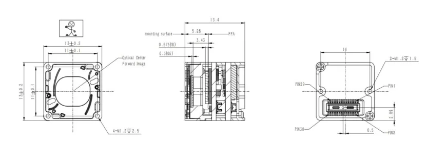
For a separate bare-core comparison, CAMCUDA SuperMini 640 / 640T uses a 640 x 512, 8 um detector with NETD ≤40 mK at 25 °C, F/1.0. SuperMini 640 is 50 Hz imaging-only; 640T is 30 Hz thermographic. Its 13 x 13 x 13.4 mm and <3.5 g references exclude optics and boards, and typical core power is ≤0.5 W at 25 °C, excluding the expansion board. Integration uses multiple power rails, 1.8 V UART and an external video-buffer IC for CVBS; use the SuperMini product manual for its own 30-pin interface and power sequence. Compare complete configurations before choosing the smaller bare-core footprint.
Application case: an outdoor utility payload buyer rewrites the RFQ
A European integrator starts with an hd thermal imaging camera core request for a compact UAV payload that will inspect utility equipment and later support fixed outdoor monitoring. Teledyne FLIR’s SIRAS drone coverage is useful field-context inspiration because it frames thermal payloads around public safety and industrial inspection missions. The integrator’s first email says only, “Please quote HD thermal core with USB.” The supplier can answer that email, but the answer will not protect the project.
The better RFQ reads: “We need a compact 640 x 512 uncooled LWIR module for a UAV payload and a separate fixed outdoor monitoring product. Please review AeroMini 640 with the chosen imaging or radiometric version, factory frame rate, lens and tailboard. Check the complete assembly against our envelope and weight budget, using the 21 x 21 x 28 mm and <20 g references only with their lens/flange exclusions. Confirm USB video for development, board-specific serial control, CVBS for our recorder, lens/FOV for utility equipment at defined distances, matched CAD and electrical documents. For the fixed-site version, review our protective enclosure, mounting, power and field conditions separately. Please also review the requested compliance/NDAA documents for the exact configuration and a possible North America customer.”
That request is not longer for the sake of being formal. It lets engineering check the host and bracket, lets field operations explain the image job, and lets procurement know which documents are tied to the exact configuration.
Common mistakes when sourcing an hd thermal imaging camera core
- Treating HD as the whole requirement. Resolution helps only when paired with the right lens, distance, video path, and operator workflow.
- Testing one interface and deploying another. USB video on a bench does not answer board-specific serial control, CVBS, recorder, or low-latency field-viewing questions.
- Using module dimensions without cable and lens review. AeroMini’s 21 x 21 x 28 mm reference excludes lens and flange; cable exit, tailboard, bracket clearance, lens path, and enclosure window still decide fit.
- Waiting for procurement to ask document questions. Required compliance/NDAA documents and their configuration-specific applicability should be discussed during RFQ.
- Comparing high-resolution cores without a target scene. A roof, solar panel, utility connector, perimeter event, and robotics scene may need different optics and workflow assumptions.
RFQ checklist before ordering an hd thermal imaging camera core
| RFQ field | What to provide |
|---|---|
| Application | UAV payload, outdoor field monitoring, industrial inspection, robotics, security monitoring, or embedded OEM device. |
| Image job | Target size, target distance, scene width, flight height or mounting distance, thermal contrast, and operator workflow. |
| Core expectation | 640 x 512 LWIR module path, imaging or temperature-measurement requirement, factory frame rate, and lens/FOV needs. |
| Host system | Processor, recorder, display, controller, edge computer, analog transmitter, or development PC. |
| Interface | Exact core or tailboard, host video format and rate, serial electrical levels, cable route, and CVBS receiver requirements for the selected configuration. |
| Mechanical envelope | Available volume, bracket sketch, lens opening, cable direction, module orientation, vibration expectation, and service access. |
| Power and environment | Available voltage, payload power budget, heat path, operating temperature, humidity, enclosure, and outdoor exposure assumptions. |
| Documents | Datasheet, matched assembly CAD, electrical interface reference, board/firmware/host software resources, configuration notes, and requested compliance/NDAA documents for review. |
Turn the HD core request into a buildable module RFQ
If your team is evaluating an hd thermal imaging camera core, send CAMCUDA the target scene, host device, receiver path, bracket envelope, destination market, and document needs before the sample order. Start with AeroMini 640 for the selected 640 x 512 lens/tailboard path, then confirm the imaging version, factory frame rate, board-specific video and control, lens/FOV, assembly CAD and required procurement documents. Compare SuperMini separately when a bare-core host design is appropriate.
Review AeroMini 640 | Compare SuperMini 640 / 640T | Check support downloads | Request an engineering quote
FAQ
What does hd thermal imaging camera core mean for an OEM buyer?
It usually means the buyer wants a higher-detail thermal module, often around a 640-class core, for integration into a payload, device, or inspection system. The buyer still needs to define lens, interface, mechanical, host, and document requirements.
Is 640 x 512 always enough for inspection?
Not automatically. It can be a strong HD-class starting point, but the useful result depends on target distance, target size, FOV, lens, thermal contrast, image processing, and how the operator uses the output.
Is AeroMini 640 a complete camera?
No. AeroMini 640 is an uncooled LWIR thermal camera core for UAV payloads and OEM integration. The selected lens and tailboard define the supplied assembly. Host electronics, enclosure, power, lens/FOV, video path, and control path still need review.
Why should CVBS be discussed for an HD thermal core?
CVBS can matter when the receiving system uses an analog transmitter, monitor, recorder, or low-latency viewing path. Confirm the selected AeroMini board’s output and the receiver format during RFQ; bench USB performance does not establish the field video result.
Does USB video solve the whole interface problem?
No. USB video may be right for development and host processing, while board-specific serial control and CVBS may be relevant for field use. AeroMini’s USB + CVBS + MIPI and Type-C + CVBS boards have different connection guides. Match the datasheet and SDK resources described in the product FAQ to the actual board, firmware, host, output format and rate, then validate the complete path.
How compact is AeroMini 640?
The published dimensions are 21 x 21 x 28 mm and weight is <20 g, excluding lens and flange. Request the complete selected lens/tailboard assembly CAD and mass, then review connector route, cable bend, bracket, and enclosure constraints. The separate SuperMini bare-core comparison uses different exclusions and does not supply an AeroMini assembly drawing.
Should North America buyers request an NDAA statement?
Yes, when procurement or customer review requires it. Request the applicable statement and supporting documents for the exact product configuration, destination market and intended use. Have procurement review the evidence; neither document availability nor eligibility should be assumed.
Can one HD thermal core support both drone and outdoor monitoring projects?
It can be evaluated for both, but the RFQ should separate the use cases. Drone payloads care about weight, bracket, vibration, and live viewing. Outdoor monitoring adds enclosure, mounting, power, and long-duration field conditions.
What should be included in the first RFQ email?
Include the application, target geometry, host device, video and control interfaces, mechanical envelope, power budget, environment, destination market, sample quantity, document needs, and any CVBS or NDAA requirements. Identify the selected imaging version, factory frame rate, lens and tailboard so the quotation and sample test plan refer to the same assembly.
What is the biggest sampling mistake?
The biggest mistake is ordering against a resolution label without defining the host system. A sample should be tested against real video path, bracket fit, field target, documentation, and repeat-purchase needs.