uav thermal imaging: 4 Reliable Preflight Notes Before the Payload Leaves the Truck
Field note for UAV payload engineers and sourcing teams
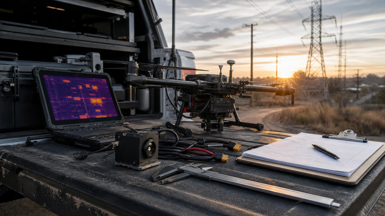
Consider an illustrative preflight scene: a utility inspection team is parked beside the truck at 6:20 a.m. The drone is ready, the battery plan looks clean, and the buyer says the sample only needs to prove that uav thermal imaging works for the next patrol route. Then the payload engineer asks a quieter question: where will the thermal evidence go after the flight?
That is the moment this article is about. A good thermal image is useful, but it is not the whole acceptance test. Before the aircraft leaves the truck, the team still has to confirm payload fit, video and control path, lens/FOV expectations, documentation, and the procurement wording that will appear in the next RFQ.
Quick answer: what should be settled before a UAV thermal imaging flight?
Before a demo or sample flight, settle four notes: what the thermal view must prove, how the payload fits the aircraft, how video/control/evidence will move through the system, and which RFQ documents procurement will need. A current module reference is the Featured CAMCUDA AeroMini 640 in its non-radiometric, 9 mm, USB + CVBS + MIPI configuration. It supports thermal imaging without temperature measurement; the 60 Hz factory default and optional 30 Hz configuration do not mean every output runs simultaneously at that rate. Confirm the selected board, host, complete payload mass and document package before flight.
uav thermal imaging is a field workflow, not just a sensor choice
NVIDIA’s June 1, 2026 physical AI and Jetson article discusses bringing AI into real-world systems. That is useful context for uav thermal imaging: the aircraft, payload, operator screen, evidence file and maintenance decision belong to one workflow. It does not establish that a particular thermal module is compatible with Jetson or that an inspection workflow has been validated.
Micron’s “The rise of edge AI” provides context for processing data near its source. A thermal payload still needs a defined path through its host board, display, recorder and inspection workflow. Teledyne FLIR’s 2022 SIRAS launch article is a historical example of combining thermal and visible views for public-safety and industrial inspection; SIRAS is now listed as discontinued. Neither article demonstrates CAMCUDA module performance or compatibility.
The CAMCUDA buyer problem is narrower than those large platform stories. An OEM or integrator wants to know whether a compact uncooled LWIR module can become a repeatable UAV payload choice without a late bracket change, video-path surprise, or documentation delay.
4 reliable preflight notes for a UAV thermal imaging payload
These notes belong in the first preflight conversation, not in the post-flight recap. They turn a promising demo into a cleaner sample order.
| Preflight note | What to confirm | Why it changes the RFQ |
|---|---|---|
| 1. Evidence target | What the thermal view must show: an apparent hotspot, insulation-related pattern, equipment anomaly, perimeter activity or field-service triage. | The lens/FOV, distance, palette, capture path, and operator review depend on the decision being made. |
| 2. Payload fit | Module weight, board dimensions, lens space, cable bend radius, bracket clearance, vibration, and thermal management. | A sample can stream on a bench and still be awkward inside a gimbal, pod, or lightweight inspection airframe. |
| 3. Video and control path | Required USB, CVBS or MIPI video mode; host capture format and rate; and the board-specific serial control path. USB video alone does not establish USB serial control. | The pilot may need an engineering laptop, embedded host, recorder, VTX path, or local service screen. |
| 4. Procurement packet | Current datasheet, matched interface reference and complete-assembly drawing; ask which NDAA-related statements and CE/RoHS documents can be supplied for the configuration and destination. | Required documentation and its configuration scope should be confirmed before the next sample order. |
A USB-centered evaluation path can help a team check the image and capture workflow on the bench before planning flight tests. The production architecture still needs its own review of mechanical fit, power, interfaces and the evidence path. Good uav thermal imaging planning uses the early sample to identify those questions and record what remains to be tested.
uav thermal imaging product facts from the Featured AeroMini 640 module
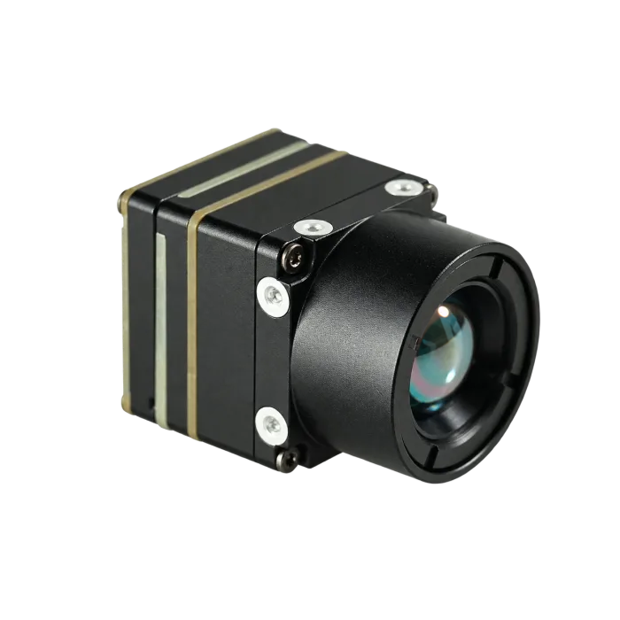
The CAMCUDA AeroMini 640 is a current Featured product. The reference here is its non-radiometric 9 mm model with the USB + CVBS + MIPI interface package. It is a module for UAV and OEM integration; the aircraft, enclosure, gimbal, radio, host and their acceptance testing remain part of the integrator’s design. The published core dimensions, mass and power below do not describe a complete flying payload.
| Component model | AeroMini 640, non-radiometric, 9 mm, USB + CVBS + MIPI |
|---|---|
| Detector type | Vanadium oxide uncooled infrared focal plane detector |
| Resolution | 640 × 512 |
| Non-radiometric factory frame rate | 60 Hz factory default; optional 30 Hz factory configuration. Confirm the rate for each selected output and host. |
| Pixel pitch | 12 μm |
| Spectral range | 8–14 μm |
| NETD | ≤30 mK at 25°C, F/1.0 |
| Supply voltage | Illustrated POWER_IN1 and POWER_IN2 pins: 5 V only. Confirm the selected board’s complete power requirements before wiring. |
| Typical power consumption @ 25°C | <0.5 W typical module consumption at 25°C; complete-kit power may differ |
| Digital video | USB and MIPI paths in the selected package; confirm format, firmware, host support and simultaneous-output limits |
| Analog video support | CVBS in the selected package; confirm PAL/NTSC mode and delivered board configuration |
| Communication interface | 16-pin board: RS232_RX/TX at pins 3/4, signal levels not specified in that pin table. 26-pin interface: UART0 TX at pin 19 and RX at pin 20, both 3.3 V. |
| Weight | <20 g, excluding lens and flange |
| Dimensions | 21 × 21 × 28 mm, excluding lens and flange; request the complete 9 mm assembly drawing |
| Operating temperature | −40°C to +80°C |
| Storage temperature | −50°C to +85°C |
| Humidity | 5–95%, non-condensing |
| Vibration | Request the configuration-matched vibration test report and compare its mounting, axes, profile and acceptance criteria with the aircraft requirement. |
| Shock | Request the configuration-matched shock test report and compare its pulse, directions, mounting and acceptance criteria with the payload requirement. |
| Current listed price | Check the current configured price or request a quotation stating camera version, factory rate, lens, interface, quantity, destination and delivery terms. |
Those numbers matter when tied to the assembled payload. The published <20 g mass and 21 × 21 × 28 mm dimensions exclude the lens and flange, so add the selected optics, board, cables, enclosure and mount to the integration budget. Measure complete-system power instead of treating typical module consumption as a kit limit. USB video can support evaluation, but the serial control path must be checked separately. For uav thermal imaging using an analog monitor, recorder or video transmitter, specify CVBS mode and confirm the delivered configuration. Non-radiometric imagery shows thermal contrast; it does not provide calibrated temperature readings.
A short field example with real constraints
Illustrative utility patrol sample flight
In this illustrative scenario, an integrator is preparing a sample flight for a utility yard and nearby roofline. The aircraft has a small payload allowance after bracket, wiring and vibration isolation are counted. The inspection lead wants an operator view during flight, engineering wants host-side capture for review, and procurement needs to ask which configuration-specific NDAA-related documents can be supplied for the intended North America customer. None of those requirements is settled by the module photograph or a good-looking frame alone.
This is where a single phrase like “thermal drone camera” is too broad. The useful uav thermal imaging question is whether the module can support the evidence path the team actually needs. A high-contrast thermal frame from one pass might look impressive, but if no one records the asset ID, distance, lens assumption, capture method, or interface configuration, the second sample order will still be vague.
A realistic mistake is approving the best-looking palette image as the purchase trigger. Thermal palettes can help operators see contrast, but they do not replace the boring acceptance details. The review should include the working distance, whether the target was stationary or moving, whether the host recorded video or stills, whether a visible reference was used, and whether the same payload route can be repeated on the next aircraft.
Teams planning UAV inspection work can use CAMCUDA’s drone thermal camera application page to frame payload requirements. For later field-service, utility-yard, perimeter or fixed-observation use, the outdoor and field thermal imaging page helps describe the operating environment. Use the Thermal Imaging Calculator to compare scene coverage and sampling for the intended lens, distance and target size; its geometry and DRI assumptions are planning aids, not a guarantee of detection, recognition or inspection success.
Interfaces and documentation that should move into the first UAV thermal imaging RFQ
Interface language is where sample conversations often drift. State whether USB is for evaluation video or the production capture path, and specify the host OS, format, rate, recording method and separate control interface. The USB-IF Video Class 1.5 document set is a standards reference. It does not establish that the ordered module implements every UVC feature, works with a particular host or exposes a USB serial port. Use the configuration-matched module documentation and a host test for those decisions.
For a live operator monitor or analog video transmitter, specify CVBS and the required PAL/NTSC mode in the RFQ. AeroMini’s USB + CVBS + MIPI, Type-C + CVBS and CVBS-only packages have different supplied boards and cables. The reference configuration here is USB + CVBS + MIPI; use the separate matched guide if ordering Type-C. Confirm which outputs can operate together, at what delivered rate and with what host settings before approving the sample.

Documentation belongs in the same early conversation. Start with the current AeroMini datasheet, interface section, product FAQ and the official developer-resource directory; confirm document, firmware and board revisions before implementing commands or host capture. On the 26-pin interface, UART0 TX is pin 19 and RX is pin 20, both 3.3 V; POWER_IN2 pins 12, 25 and 26 are 5 V inputs. The 16-pin RS232 table does not specify its signal voltage, so do not assume it is interchangeable with that UART.
Ask which NDAA-related statements and CE/RoHS documents can be provided for the exact configuration and destination, using support downloads, the support FAQ, EU documentation information and Contact / RFQ. These links do not certify an assembled aircraft or guarantee a document’s availability.
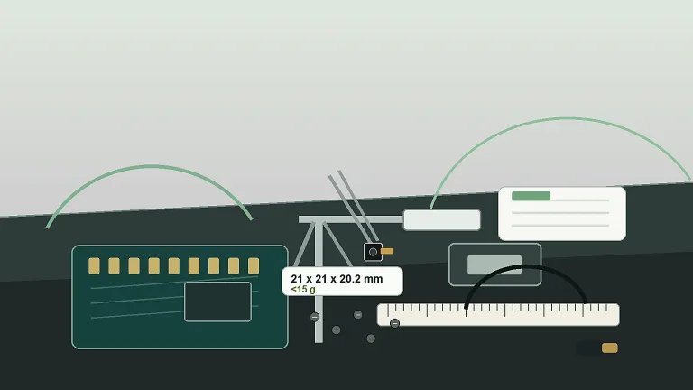
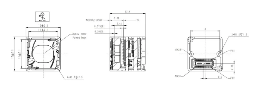
For a separate compact-core option, the Featured CAMCUDA SuperMini 640 imaging-only model at 50 Hz has published 13 × 13 × 13.4 mm bare-core dimensions excluding the lens, flange and user expansion board. Its V1.0.0 product manual, Figure 4.1 on physical page 13, is the source for the drawing below. Use it only to assess this SuperMini option. Request the complete AeroMini 9 mm assembly drawing for the main configuration in this article; the separate AeroMini 7 mm STEP model is not a substitute.
Common UAV thermal imaging mistakes before sample ordering
1. Treating the first good image as acceptance
The first good image proves that the module can show useful contrast in one condition. It does not prove repeatable evidence, payload fit, or procurement readiness.
2. Choosing the video path after the bracket is designed
Connector direction, cable route, recorder path, and service display all affect mechanical design. Put the interface decision into the payload drawing review.
3. Forgetting the operator view
Some programs only need host-side capture. Others need a live view during setup or inspection. If an analog display, recorder or VTX path is required, include the CVBS mode, board package and intended simultaneous outputs in the first configuration review.
4. Leaving compliance language until procurement asks
List the exact procurement and destination requirements early, then ask which supporting NDAA-related statements, CE/RoHS documents, assembly drawings and interface references can be supplied. Review their scope before treating the procurement packet as complete.
5. Comparing module prices without comparing integration burden
A lower quote can become slower if the team still has to rebuild brackets, rewrite capture software, or chase undocumented interface details.
For buyers comparing adjacent options, the broader thermal imaging cores, thermal modules, and uncooled thermal modules category pages can help frame the product family before the RFQ narrows to a specific configuration.
RFQ checklist for a cleaner UAV thermal imaging handoff
| RFQ field | What to write |
|---|---|
| Aircraft and payload constraint | Available payload mass, space, bracket limits, vibration expectations, cable path, and power rail. |
| Inspection target | Utility asset, roof, solar panel, perimeter, equipment hotspot, field-service triage, or another named use. |
| Working distance and FOV | Expected target size, working distance, lens/FOV target and visible reference imagery; state separately if calibrated temperature readings are required, because the selected AeroMini configuration provides imagery only. |
| Video and control path | Selected USB, CVBS or MIPI video path; host format and rate; board revision; serial control pins and electrical levels; and any simultaneous-output requirement. |
| Evidence workflow | Live operator view, recorded video, still capture, post-flight review, or embedded host processing. |
| Documentation | Current datasheet, complete-assembly drawing, matched electrical interface guide and firmware revision; ask which NDAA-related and CE/RoHS documents are available for the configuration and destination. |
Make the sample flight easier to approve
Use the first RFQ to describe the aircraft, target, host, evidence path and required documents. Review the Featured AeroMini 640 non-radiometric 9 mm configuration against those requirements, and assess SuperMini 640 separately if a smaller bare core suits the design. Freeze the selected lens, board, firmware and tested output mode with the approved sample so a repeat order has a clear reference.
Review AeroMini 640 | See drone thermal camera applications | Check support downloads | Send an RFQ
FAQ
What should a UAV thermal imaging sample flight prove?
It should prove the target evidence, payload fit, video/control path, and documentation handoff. A clean thermal frame is only one part of the acceptance decision.
Is the AeroMini 640 a finished drone payload?
No. It is a thermal imaging module for OEM integration. The reference here is non-radiometric AeroMini 640 with a 9 mm lens and USB + CVBS + MIPI package. The buyer still has to define the aircraft, mount, enclosure, host, power, display and recording path, and the required RFQ documents. Core mass, dimensions and typical power do not describe that complete payload.
Why is 640 × 512 resolution useful for UAV thermal imaging?
It can give more scene detail than lower-resolution thermal paths, but the right answer still depends on target size, working distance, lens/FOV, flight height, and review workflow.
When should CVBS be mentioned in a UAV thermal RFQ?
Mention CVBS when the project needs analog video transmission, an analog display, a recorder or a service monitor. Specify PAL/NTSC requirements and the selected board package, and confirm the delivered output rate and permitted simultaneous outputs. An analog-video requirement does not establish host compatibility or a complete flight-ready payload.
Does USB video mean the whole payload architecture is finished?
No. USB video can support evaluation and host-side capture, but production still needs mechanical, cable, power, control and service-view decisions. It does not establish a USB serial interface. Check the selected board’s pin definitions, signal levels, firmware and commands separately; validate the intended format and rate on the actual host.
What documentation should North America buyers request early?
Request the current datasheet, complete-assembly drawing, matched electrical interface guide, firmware revision and configuration list. If the procurement path requires NDAA-related statements or CE/RoHS evidence, identify the exact requirement and destination and ask which documents can be supplied for that configuration. A product page or document request alone does not establish compliance of the complete aircraft.
How should a field team avoid approving the wrong evidence?
Record the target, distance, lens/FOV assumption, capture path, palette context, aircraft setup, and whether the same result can be repeated in the next sample flight.
Which CAMCUDA pages should a UAV payload buyer open next?
Start with the AeroMini 640 product page and its integration FAQ, then the drone thermal camera application page, support downloads and Contact / RFQ page. If core size is the constraint, compare the separate SuperMini 640 option using its own manual and assembly drawing.
Why include outdoor and field thermal imaging in a UAV article?
A UAV inspection program can feed a later field-service, utility-monitoring or outdoor-observation workflow. The application context helps the RFQ specify the operating environment, recording needs and review process alongside the aircraft requirements.
Technical author: Daniel · Hardware Support; Sales contributors: Vivian, Lena and Sophie.